A thesis presented for the degree of
Doctor of Philosophy
in
Mechanical Engineering
in the
University of Canterbury
Christchurch
New Zealand
by
D.R, WALES B.E.(Hons)
Abstract
(i)
Nomenclature
(iii)
CHAPTER ONE Introduction
1.
1.1 Background
1.
1.2 Scope of Work
4.
CHAPTER TWO Film Equations
7.
11.1 Reynolds Equation
7.
11.2 Non-dimensional variables
13.
II. 3 Film boundary conditions
14.
11.4 Finite difference solution
16.
II.S Oil film forces
23.
11.6 Dynamic bearing coefficients
27.
II. 7 Oil film work
34.
CHAPTER THREE Computer Progr'am
46.
III. 1 General Description
46.
III. 2 Bearing geometry 49.
III.3 Locus stepping - directly loaded journal
51 •.
III.4 Locus stepping with rotor model55.
CHAPTER FOUR Program Evaluation
63.
IV.l Program Accuracy
63.
IV.2 Oil film forces
68.
IV.3 Dynamic bearing coefficients
71.
IV.4 Directly loaded bearing
73.
V.2
V.3
V.4
Linear extrapolation of dynamic utilisation previous cycle data Second , smoothed data scheme V.S Effect of locus accuracy constants
V.6 Summary
coefficients
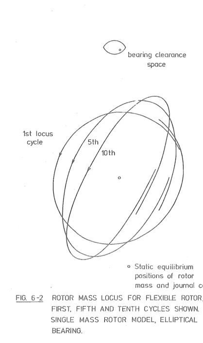
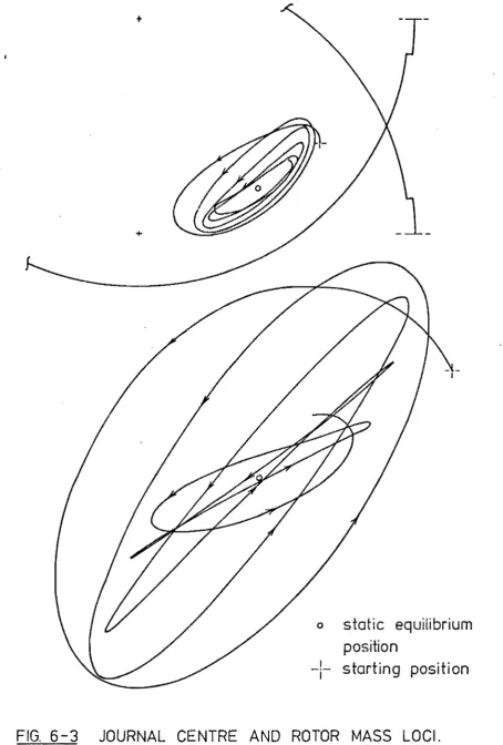
CHAPTER SIX Work Performed by the Oil Film on the Journal and the Behaviour of the Rotor
VLI
VI .2
VI. 3 VI. 4
Accuracy of the oil film work calculation
Correlation of rotor locus growth and oil film work Prediction of rotor stability
Summary
CHAPTER SEVEN The Influence of Bearing Parameters on the
Work Done by the oil Pressure Film on the Journal VII.l Test data
VII .2 Effect of LID on full circular journal whirl
VII. 3 Influence of bearing geometry VII. 4 Influence of load angular velocity VII. 5 Influence of load magnitude
VII. 6 Effect of superimposed synchronous force VII. 7 Summary
CHAPTER EIGHT Conclusion
VIlLI Future work
ACKNOWLEDGEMENTS REFERENCES
APPENDIX Computer Program Description and Source Listing
The aim of the work reported in this thesis was to develop a method, suitable for general design work, to determine the stability of a simple rotor mounted in hydrodynamic bearings, The rotor model used was a simple spring mass system, but the bearing model allowed a comprehensive range of bearing cross-sectional shapes and grooves to be assessed. The oil film equations were solved by the successive over-relaxation finite difference technique.
The problem was approached by considering the energy balance of the bearing-rotor system. The hydrcdynamic oil pressure film in the bear-ing performs work on the journal and this is largely responsible for the decay or growth of the rotor motion. The behaviour of a simple rotor was investigated to determine if its influence on the bearing could be represented by a simple force locus as this would allow the oil film
work to be calculated without marching out the rotor locus. In general, the force exerted by the rotor on the journal is too complex to allow a direct assessment of the stability of a system by this technique.
The flexibility and ease of operation of the directly loaded bearing computer program make it useful for comparisons of bearing design feat-ures and load conditions. An investigation was carried out into the effect of the bearing parameters on the oil film work when the journal is loaded with a circular force locus.
Unless otherwise specified, the following symbols are used in the text. A dot above a symbol, e.g.
e,
indicates the derivative with respect to time.ACC Br bxx bxy byx byy
em
D DEL DT e FX,FY FXJ,FYJ fx,fy H h Ks kxx kxy kyx kyy LRelaxation convergence tolerance Rotor damping coefficient
;)FX/c)){j ;)FX/aYj ;)FY/;)Xj aFY/;)Yj
Minimum radial bearing clearance with the journal centre at the bearing centre,
Journal diameter.
Resultant non-dimensional oil film force Non-dimensional time step
Journal eccentricity
Non-dimensional oil film force, x and y components Non-dimensional force applied to journal, x and y components
Dimensional force, x and y components Non-dimensional oil film thickness
Dimensional oil film thickness Rotor shaft stiffness
;)Fx/aXj ;)FX/;)Yj ;)FY/;)Xj ;)FY/;)Yj
LOADAC Load accuracy tolerance
m Number of circumferential grid divisions
Mr Rotor mass
n Number of axial grid divisions
ORF Over-relaxation factor
p Non-dimensional pressure
,z
Non-dimensional pressure at point X, Zp Non-dimensional pressure-height parameter (PH2)
Non-dimensional pressure-height parameter at point X, Z
p Dimensional pressure
R Journal radius
r Radial bearing clearance
Radial co-ordinate of segment cel .. tre with respect to bearing centre
RLV Relative load velocity, ~/~
u,v
Journal surface velocity, X and Y components u,v,w Velocity in the x,y and z directions respectively WORK Non-dimensional work performed by the oil pressurefilm on the journal
X,Y,Z Non-dimensional cartesian co-ordinates of the bearing surface
x,y,z General dimensional cartesian co-ordinates Xj, Yj Non-dimensional journal centre co-ordinates xj, Dimensional journal centre co-ordinates Xr,Yr Non-dimensional rotor mass co-ordinates
y Angular co-ordinate of journal centre AS Non-dimensional applied static load
AT
Non-dimensional applied dynamic load1.1
P
Journal eccentricity ratio under static load alone Angular position on bearing surface
Angular co-ordinate of segment centre with respect to bearing centre
Viscosity coefficient Density
Shear stress
Angular position of applied dynamic load Angular posi Hon of applied 5tatic load. Attitude angle
INTRODUCTION
The aim of the ,york described in this thesis was to produce a commercially acceptable method to assess the dynamic behaviour of a
rotor mounted in hydrodynamic bearings. Although an enormous quantity. of research has been done on the stability of bearings, a satisfactory method of analysis for industrial applications has not been developed. Those existing are either derived with approximations limiting their application or ~equire considerable computer time to analyse a more comprehensive model, rendering them suitable only for problem cases or final desian checks.
Thus, a programme of research was started to analyse journal bearing dynamic behaviour using a comprehensive bearing model, but keeping the method of analysis suitable for general design work.
I.l· BACKGROUND
A journal bearing can be simply described as a circular shaft (the journal) inside a bush of slightly larger diameter (the bearing) with a lubricant between the two allowing low friction relative
He found the film was produced by the journal running
in the bearing, thus forming a converging wedge. The viscous shear forces imposed on the lubricant by the rotation of the journal force the fluid into the wedge thereby increasing the pressure. A second mechanism of pressure generation occurs when the radial position of the journal in the bearing is not constant. The journal, approaching the bearing surface, forces out the lubricant creating a pressure film independent of the shaft rotation. These two mechanisms for generacing load bearing oil films give rise to what are known as wedge and squeeze films respectively. _
The equation derived by Reynolds forms the basis of present hydrodynamic bearing theory and bears his name. He presented a solution for a pure wedge (e.g. an inclined plate) of infinite width. Sommerfeld (3) in 1904 applied the theory to a full journal bearing of infinite length, but he failed to allow for film disruption in regions of negative pressure. The validity of this assumption was commented on by a number of researchers, including Reynolds, but it was S\vift (4) in 1931 who established the boundary condition that the film ended with both the pressure and pressure derivative zero.
solution was put forward by Ocvirk(S) in 1952.
Another closed He assumed the bearing to be short and hence the axial pressure derivatives to be
much greater than those in the circumferential direction. In this way he justified omitting the circumferential derivatives from his analysis.
solution for a bearing of finite length was made by representing l:he pressure with an infinite series until Christopherson (6) I 1941,
iterative technique, known as the relaxation method, developed by
(7)
Southwell a year earlier. Christopherson used the same film boundary conditions as Swift and included in his solution the variat-ions of the lubricant viscosity with pressure and temperature.
Iterative methods of solution have been used by many investigators since and form the basis of the technique described in this thesis. They are well suited for high speed digital computers. The
programm-ing is relatively simple because the solution involves the repeated use of one set of equations. These methods also allow a variety of film boundary conditions to be satisfied, permitting bearing design features such as grooves to be included in the solution. Series solutions are still used, but they lack the flexibility of the finite difference technique.
The advent of digital computers and the increasing demand for better bearing performance stimulated an acceleration of work in the late 1950s and 1960s. Researchers considered the effects of assumpt-ions made in deriving and solving Reynolds equation, for example turb-ulence, lubricant inertia, viscosity changes and bearing distortion, and conducted investigations into such topics as the influence of lubricant supply conditions, heat transfer and lubricant flow. Most of this work has been done for statically loaded bearings as computation time is still long and thus research expensive.
available to designers.
This approach assumes that for small movement of the journal about its static equilibrium position, the film forces can be
des-cribed by constant stiffness and damping coefficients, Thus repeated solutions of Reynolds equation are avoided and the bearing-rotor be-haviour is simpler to analyse. A direct a~sessment of a system's
stability is possible using, for example, the Routh-Hurwitz criterion (lO) •
Recent non-linear theoretical investigations have generally employed approximate fiim solutions to shorten computation time. As well as the long and short bearing solutions menticned, new methods have been developed, For example, Warner - (11) ,1963, solved the film equation by multiplying the long bearing solution by a factor representing
side leakage. Shelly and Ettles (12) , 1970, assumed an axial pressure distribution to reduce their finite difference scheme to one dimension.
More comprehensive solutions have been produced. Someya (13) I 1964,
investigating the stability of a flexible rotor, used a series solution
(14)
and Lloyd ,1966, a finite difference scheme in determining the dynamic behaviour of bearings in reciprocating machinery. Both of
these capitalised on the circumferential symmetry of circular bearings to reduce computation. Ware (15) , 1975, cons~dered . the problem of a multi-mass rotor, including gyroscopic effects, supported in a number of bearings. He used a finite difference scheme which could handle non-circular bearing cross-sections.
1.2 SCOPE OF WORK
The work undertaken is divided into three parts
rotor loci. Primarily this involved better util<-isation of the information obtained from solving the film equations.
(ii) Calculation of the work performed on the journal by the oil pressure film and with a knowledge of the rotor energy balance, an assessment of the system stability.
(iii) The third section, arising from (ii) is an investig-ation into the effects of various operating parameters on the work performed on the journal by the oil film.
A successive over-relaxation finite difference scheme is used to solve Reynolds equation and to calculate the displacement and velocity coefficients. The film boundary conditons adopted are those used by Swift
P
=
dPaX
=
o
at film formation and disruption. In defining the bearing model, the main assumptions are incompressible, isoviscous and inertialess lubricant and the journal and bearing are aligned and rigid. These assumptions are discussed more fully in Chapter 2. The model allows a variety of bearing geometries to be analysed, including non-circular cross-sections and axial and circumferential grooving.
The rotor model used is a single mass mounted symmetrically between two similar bearings on a light elastic shaft. This allows the system to be represented by a mass and a light journal joined by a spring.
Provision has been made for viscous damping on the mass. Some work '.'las conducted on a twin spring-mass-damper system.
CHAPTER
FlU:!. EQUATIONS
In this chapter a brief description of the derivation of Reynolds equation is presented, together with the assumptions made for the present investigation. A fuller mathematical treatment of the
der~vat~on · · can e ound b f ~n P~n . . k us and Stern11cht . (16) . The numerical solution of this equation by the finite difference technique is describ-ed and the method usdescrib-ed to determine the dynamic bearing coefficients outlined. The final section considers the energy transfer between the oil film and the journal 8.nd the influence this has on bear:Lng and rotor stability.
11.1 REYNOLDS EQUATIO~
The equation of motion for a Newtonian fluid is the Navier Stokes equation. This is derived by considering the forces on an element of fluid and applying Newtonls Second Law.
ship for a Newtonian fluid :
dU
T :::;
11dX
The stress-strain
relation-.is introduced, giving the x component of the general Navier stokes equation as
That is:
f _ dP +
l
P x dX dX (2 dU 11
dX
d
+
-dY
( (
dV
+
dU))
11
dX
dy
+
du
:=
P
dtbody force
+
pressure force+
viscous force=
inertia force. Similarly for the y and z components.(i) The film thickness, YH is small compared to its expanse in the x and z direction. It is usual design practice to have the clearance ratio, r/R, between .001 and .002. Thus
(a) the curvature of the bearing is negligible allowing the film to be considered in cartesian co-ordinates; (b) the pressure and viscosity are constant across the
film, thus ap
dy ==
o.
The variation of viscosity can be significant, but
treating it as a variab~1 e makes the problem too complex; (c) the velocity derivatives with respect to }' are greater
than those with respect to x and z and the y veloc-ity (v) is less than the other two compon.ents (u,\V'). (ii) The lubricant inertia forces are small.
(iii) There are no body forces, e.g. gravitational or magneto-hydrodynamic forces.
(iv) The flow is laminar. This is not true for large bearings. The film is turbulent \-lhen the Reynolds number
[u~p
j
is greater. than 2000.(v) There is no slip at the bearing surfaces. This is satis-factory for liquid lubricants, but considerable can occur with thin gas films.
Reynolds, in his analysis, also assumed the lubricant to be in-compressible, but it is unnecessary to assume this at this stage.
The three components of the Navier Stokes equations reduce to
1 ap
a
2u-11 ax ay2
1
.£R.
d-
==Integrating these twice with the boundary conditions
u = U
o
w= Wo
at y :::: 0U :::: U
h w ::::::
W
h at y "" h yields(y-h) + (l-l.) U
o
yu ::::: y
+ hUh h
(y-h) + (l-l. ) y
w ::=: y
Wo
+h
w
h h
The continuity equation for steady flow is apu + a
ax
o
Substitute for u and w, integrate with respect to y between the limits of hand 0 and differentiate to obtain
+ (Ph J.l 3 dPJ' az 6 (U -U )
~
o
h axA number of the terms on the right hand side can be removed when apply-ing this equation to a journal bearapply-ing. By taking the z axis as parallel to the bearing centre (Fig.2-l), the velocities Wo and W
h can be made zero. Any axial movement of the journal would in most cases be small, of a size comparable to the bearing clearance, and occur at a frequency similar to the shaft speed. Thus as r/R ~ 001, w/u
d
The second term, 6ph ax (UO+U
h), is also small. Referring to Fig.2-2, the boundary velocities U
o
and Uh are:
o
WRcos(n+S) +
e
sin (y-8-n) + etcos(y-8-n)F
-1
BEARING SURFACE CO - ORDINATE
h::: R + r + ro Cos(s -A +11) - e Cos(y-e-iJ)
R Cos
(11+~)
r
+ ro Cos(e -
i\) -
e Cos(s
-V)
Uh:::
wR Cos(l1 +
~ ) +
e
Sin(y - e - 11) + eyCos(y - e
-11)
"I"
wR
Vh
-wRSin(l1+~)-
e
Cos(y-e 11) +eySin(y e l l )
we Sin(y
e) -
Wfo
Sin(s
i\) -
eCos(y
e)
<I.eySin{y e)
BEARING GEOMETRY -
DEFINITION OF OIL FILM
THICKN
VELOCITY.
a he he • .
hax (OO+Uh)~ -
R
Cos (y-e) + R yS~n (y-8)Again referring to Fig.2-2, the film thickness can be expressed as h
=
R+r + r Cos (e-A-n) - e Cos (y-O-n) -R Coso
.
(ntS)
2
Differentiate and neglect terms of order (r/R) or smaller,
Thus
ah
-Also
rO
- Sin (8-A)
R ~ R Sin (y-8)
ewsin (8-y) - rOW Sin (O-A)
-eysin (8-y)
e
Cos (6-y) + we Sin (8-y)h h . . h a ( ) . 11 h 0 ah
T us t e term conta1n1ng ax U
o
+
Uh 1S sma er t an Vh and h ax by a factor r/R.Reynolds equation is now reduced to
== - 6 U h aph ax
+
12 P VhFor the purpose of the present investigation, four further simplify-ing assumptions were made, as follows :
(i) The lubricant viscosity is constan·t throughout the (ii) The lubricant is incompressible;
( ... ) 111 T e Journal and bearlng are perfect y a 19ned, 1.e. az h . . . I 1 . . ah
= ;
0 (iv) There is no distortion of the journal or bearing surfaces.thus the improved accuracy obtained by considering these variables was not required.
It is more convenient to express Reynolds equation in terms of the journal centre displacement and velocitYt either in polar or cart-esian co-ordinates, and the jou.:::nal angular velocity. Thus in polar co-ordinates
=
6~
(e (W-2y) SinCe-y) -wrO SineS-A)]- 2e Cos (e-y)
and in cartesian co-ordinates
:=
6~
( w(xj Sine - yj CosS)-2Cxj Cose +
yj
SinS) - wrO Sin (S-A»)11.2 NON-DIMENSIONAL VARIABLES
The variables may be non-dimensionalised with the following substitutions :
Position on the bearing surface S
X
=
2 'IT Pressure and forceP FX fx
~WLR(;r
••• 2 .la
..• 2 .lb
Displacements of magnitude comparable to the film thickness are non-dimensionalised by dividing by the radial bearing clearance r :
e: :::
H :::: e r
h
ro
1
+
COS (2TIX-A) - ECoS (2~X-y)
r xj
=
r
When dealing with dynamic loads and locus it is convenient to non-dimensionalise time. The unit of time is taken as that required for the rotating or rotor load (see Chapter 3) to sweep through one radian. Thus a non-dimensional time step is
.
DT
=
otime. ~and velocities are transformed to
.
Xj
=
For multi-lobe non-circular bearing designs the value of the radial clearance, r, used in the non-dimensional variables is the minimum radial clearance of the final bearing segment, that is, the segment which ends at
e
360 degrees (see Fig.2-2) •11.3 FILM BOUNDARY CONDITIONS
Befo~e Reynolds equation can be solved a choice of boundary con~
ditions must be made. Firstly, consider the case when the oil film is not bounded by the bearing geometry, that is, grooves or the bearing edge. There are at least five possible mathematical models.
(i) The oil film is continuous throughout the bearing clearance.
This implies a region of negative pressure where the wedge is divergent. It has long been realised that this does not occur and that the film is disrupted if the pressure drops below a certain value.
gives moderate agreement with experimental observations and has been used in cases where it the method
f 1 ' (14)
o so ut~on •
(iii) Film formation occurs at the point of maximum film thick~
ness and breakdown occurs when
P dP
ap
::::o
cornrronly used in the literature, this satisfactory reSUlts for steadily loaded aligned bearings.
(iv) The most sophisticated mathematical model assumes that film breakdown occurs when
ap
ax
=
0 Pand the film reforms when
ap
l21f H - H*where
P d~s '
P
dis = oil film disruption pressure H*
=
film thickness at breakdown.h ' d ' d b 1 b d k b (17) ' d '
T ~s was er~ve y F 0 erg an Ja 0 sson cons~ er~ng
the flow balance in the disrupted region. The film will withstand subatmospheric pressures, the disruption pressure being determined by the oil vapour pressure and the pressure at which dissolved gases come out of solution.
This boundary condition is difficult to satisfy corn-putationally. 'McCallion, Lloyd and Yous~f , (18) used an
(v) Film formation and breakdown occurs when
'oP oP
oX
==az ::::
p :=o.
These are the conditions employed in this thesis. They are ideally suited to the finite difference method of solution as they are invoked simply by setting negative pressures to zero as they occur in the calculation. This model differs from Model (iv) primarily in the point of film formation and the magnitude of the dis-ruption pressure. As these are both low pressure
regicns the oil film forces will not be greatly affected. These conditions were used by Smalley(19) and found to give good agreement with experimental results.
When the oil .-pressure film extends the full width of the bearing the axial film boundary condition is :
P == 0 when Z == 0, L
This implies the film pressure is atmospheric at the edge of the bearing.
h d · · oP
T e pressure er1vat1ve,
oZ
is not zero as this would deny side leakage.In a similar manner the junction of the pressure film and a groove can be described. At the edge of the groove the film pressure is set to a predetermined value
P P
groove
The value of the pressure derivative was not defined in this investigat-ion as each groove was assumed to supply or absorb sufficient oil to satisfy flow continuity.
II.4 FINITE DIFFERENCE SOLUTION
over-relaxation finite difference scheme on a point star grid. The program developed (see Chapter 3) is capable of handling grooved bearings of non-circular cross-section thus a flexible method of solution was a prime requirement. As far as the author is aware, this is only offered by finite difference techniques. Many other solutions exist but although quicker to compute, they invariably place greater restrict-ions on the bearing geometry.
Reynolds Equation
When marching out the journal centre locus it is mOre convenient to use cartesian than polar co-ordinates. The non-dimensional form of Equation 2.1b is :
Sin 2nx Yj Cos 2nX
24~2
(Xj- 2: (Xj Cos 2nx - Yj Sin 2nX) - rrO Sin (2nX-A) ] ••• 2.2
To improve numerical accuracy the pressure was replaced by a non-dimensional pressure-height parameter P = PH • 2 This quantity is less dependent on X avoiding the sharp peaks that occur in both the wedge and squeeze pressure films as the journal approaches the bearing surface. Substituting :
- 2¢ (Xj Cos 2nx
W
.
Yj Sin 27TX)
,
Sin 27TX Yj Cos 27TX
rO .
J
r
S~n (27TX-A) ..• 2.3-PX+6X ,Z ~ Px- 6x ,Z
Also the axial derivative
[ l\X2
12
[
6Z2
alfpJ'
12 aZIfIn brackets are the most significant terms not considered. All other terms in ReynolQs equation can be calculated directly for any point on the bearing surface.
substituting into 2.3 gives
PX,Z == (AX • P X +6x , Z + BX . Px- 6x ,z + (PX,Z+6Z + Px,Z-6Z) .C
- RHSX] / Dx ••• 2.4
1
[ 1 1 aH
J
where AX == 6x 6x -'2
aX1 ( 1 1 aH] BX == 6x +
'2
axC
=
(~r
L6z2~2
(Xj.
RHS
x := Sin 21TX - Yj 'Cos 21TX - 2<1> ()j 6{j Cos 21TX
.
rO )- Yj Sin 21TX) - r Sin (21TX-\)
2
2
(~r
2 a 2HDX ::= - - + +
6X2 L6z H
ax:?
by less than a predetermined convergence accuracy criterion,
To increase the speed of convergence an over~relaxation factor, ORF, is used. The new estimate of the pressure-height parameter is made equal to the old estimate plus the over-relaxation factor times the change in the parameter.
+
ORF[
_ n+l
Px,z
Relaxation Grid
The bearing surface is divided into a rectangular grid of m by n divisions in the circumferential and axial directions respectively. The divisions in each are of constant length, thus :
x
=
z
1
m
1 n
the non-dimensional bearing surface dimensions being 1 by 1. Variable
(14) .
grid divisions have been used by other workers to g~ve better accuracy in regions of high pressure, but for dynamically loaded non-circular
bearing geometries these are difficult to program.
Bearing geometries are restricted to those having symmetry about the circumferential centre line of the bearing surface. This is not a severe constraint, as most designs exhibit this property and it allowed the relaxation process to be limited to half the bearing surface. The existence of the second half of the bearing is accounted for in the numerical procedure by the boundary condition :
thesis. This was based on a publication by Smalley, Lloyd, Horsnell
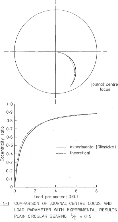
• (20)
and McCall~on giving the following results for a plain circular
bearing of length to diameter ratio .75 using these grid dimensions •
E • 5 .8 .95
-% Load Error .2 .9 6.0
Basis of Error
(Grid Size) 96 x 8
I
96 x 8 192 x 8They also found that doubling the number of axial divisions made less than 1% improvement in the accuracy of the load parameter.
Conditions
The finite difference equation, 2.4, requires knowledge of the pressure-height parameter one grid point on each side of the point of calculaticn. Thus the grid must be one row in each direction greater than the region swept by the relaxation procedure.
In the axial direction the pressure at the edge of the bearing is zero and at the centre, where the surface is free from grooves, the pressure-height parameter is reflected across the centre line as it is calculated :
=
0 I PX,!.
+ 6z2
:= p
X,!.
~ 6z2
These two points are outside the swept region and form the axial boundaries
the first derivative. To allm'l the program to handle such designs it was decided to place a groove at each discontinuity (see III-2). In this way oil flow and pressure balances can be easily achieved.
When such features are absent, the bear~ng surface is continuous and the ends of the finite difference grid must be linked. This is achieved by setting
::=
Pl':,X,z P_l':,x,Z
Again the points on the left of these equalities are outside the swept region.
The extent of the oil pressure film on the unbroken bearing surface is fixed for both build-Up and breakdown by setting negative values of the pressure-height parameter to zero as they occur in the relaxation procedure. This automatically imposes the boundary conditions :
P ::= dP ::=
az
o
discussed earlier.Grooves are allowed for by setting the pressure at each grid point within the grooved area to a predetermined value and not modifying this with the relaxation procedure.
Over-Relaxation Factor
The over-relaxation factor is approximately optimised using the
. (21)
equations given by Lloyd and McCall10n I namely :
where a ""
Thus this factor is dependent only on the bearing length to diameter ratio and the n~~er o~ grid points.
(22)
An alternative scheme, developed by Carre was considered. It involves calculating the over-relaxation factor as the relaxation proceeds and iterates to an optimum value. This would have meant a loss in efficiency as the first cycles of relaxation are computed without over-relaxation. Also, although not so important, it would have comp1jcated the relaxation routine.
Lloyd and McCallion compared the values of the over-relaxation factor calculated by those two methods and found good agreement.
Relaxation Convergence Criterion
The relaxation process is continued until the maximum fractional change in the pressure-height parameter between successive iterations is less than the convergence tolerance ACC. This is achieved by checking the inequality :
_ n+1 _n+l
P < ACC. P
at each grid point and if this is found to be true over the entire grid the relaxation is terminated.
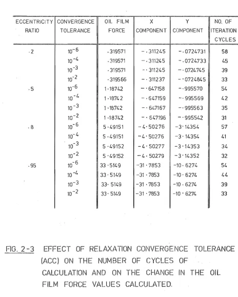
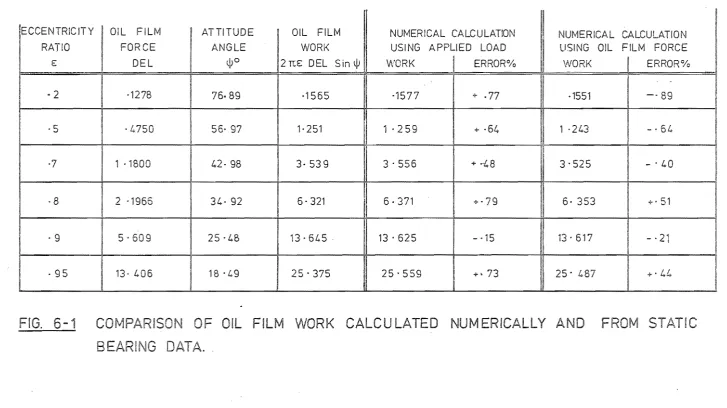
The value of ACC used in the \'lork described in this thesis is 10-3. This was chosen after a series of tests on a statically loaded plain circular bearing • Four eccentricity ratios were considered, .2, .5,
• 8 and .95 and for each the oil film forces were computed for convergence
-6 -4 -3
required was also recorded.
The results are tabulated in Figure 2-3. The change in the oil film forces as the tolerance is raised was small compared to the errors introduced by the pressure summation and grid dimensio~s. However, the saving in time, or number of relaxation cycles, was also small.
-3 -2
Increasing the tolerance from 10 to 10 saved, on an average, 4~
, but to ensure a minimal convergence error this was sacrificed.
-4
Lowering it to 10 incurred a greater time penalty whilst producing considerably less improvement in the accuracy.
11.5 OIL FILM FORCES
The oil film forces are calculated by integrating the pressure over the bearing surface :
1 1
FX 21T
ttpx,z
Cos 21TX.dZ.dXFY
=
21TflJl Px
Z Sin 21TX.dZ.dXo 0 I
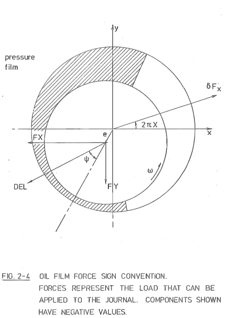
where FX and FY are the components of the non-dimensional load that can be applied to the journal (see Fig.2-4).
and attitude angle are given by
DEL
::;: y - tan -1 (FY] FX
From these the load parameter
ECCEI\jTRICITY CONVERGENCE OIL FILM X Y NO. OF
RATIO TOLERANCE FORCE COMPONENT COMPONENT ITERATION
CYCLES
·2 10- 6 .319571 - ·311245 -·0724731 58
10 -4 .319571 - 311245 - - 0724733 45
10-3 ·319571 . 311245 -·0724745 39
10-2 ·319566 -·311237 - . 0724845 33
·5 10-6 1·18742 -. 647158 -'995570 54
10 - 4 1 .18742 ·647159 -·995569 42
10 -3 1 ·18742 -. 647167 -. 995563 35
10 1 ·18742 - . 547196 -'995542 31
·8 10- 6 5 '49151 - 4- 50276 3'14354 57
10- 4 5 '49151 4' 50276 -3' 14354 41 . 10- 3 5 ·49152 -4' 50277 -3 -14353 34
10 5 '49152 -4 - 50279 -3'14352 32
.95 10- 6 33 . 5149 -31 '7853 -10· 627/.. 54 10 -4 33,5149 -31 ·7853 -10' 6274
44
10-3 33· 5149 -31 ,7853 -10·6274 39 10- 2 33' 5149 -31 - 7853 -10 . 6274 33FIG 2-
CT OF
LAXATION CONVERGEN
TOLERANCE
(ACC) ON THE NUMBER OF CYCLES OF
CALCULATION AND ON THE CHANGE IN THE OIL
[image:32.566.59.524.124.704.2]pressure
film
DEL
/
y
x
FIG. 2-4
OIL FILM FORCE SIGN CONVENTION.
FORCES REPRESENT THE LOAD THAT CAN BE
APPLIED TO THE JOURNAL. COMPONEI\JTS SHOWN
[image:33.566.65.510.76.697.2]Axial Summation
The integration performed is
=
r
PX,z dZ oalong each axial grid line in the pressure film.
Applying Simpson's rule we have
OF.,,.
..
= b.z3
[px,o
+ 4Px
,6Z + 2PX,26Z •.•••••••+ 4P
X,l-b.Z + P X ,1
1
However, the pressure at the edge of the bearing is zero
P
X,O P X,l
=
0and the pressure distribution is symmetrical about the bearing centre line, that is :
=
PX,i
+ ib.z2
Thus the integral contracts to :
i 1,2, •••• 0 n 2
= 2. b.z
3 [4PX,6Z + 2PX,26z •••.. +
px'~l
Circumferential Summation
The two integrals are
FX = 2TI ).
(b
aOF
X Cos 2'ITX.dX
FY = 2TI
I.
bOF X Sin 2TIX.dX
where a and b are the positions of film formation and breakdown respectively for each pressure film. with non~circular bearing geometries there is usually more than one pressure film due to the fact that a number of converging clearances exist. The numerical form of these integrals, using the trapezoidal rule, is :
Accuracy
FX = 2TI.6x
[~Fa
Cos 2TIa + OFa+6x Cos 2TI(a + 6x)+ ; OFb Cos 2TIb]
FY
=
2TI.6x(t
OFa sin 2TIa + •..•..OFb~6X
Sin 2TI(b-6x)+
~
OFb Sin 2TIb)The choice of the numerical integration techniques was made with reference to the work carried out by Lloyd (14) • He found that in the circumferential direction, Simpson's rule \Vas not significantly better than the trapezoidal rule. For an infinitely short bearing (Ocvirk solution) with 32 circumferential mesh points, the summation error was found to be less than 1% for € less than 0.9 rising to 5% at €
=
.97.The axial summation was found by Lloyd to require Simpson's rule.
E:
This gave an error of less than 1% for a unit squeeze film (-
=
1)w
L
when €
=
.975 andD
.75.II.6
calculated from the relationships.
FX
FY
aFX ~. aFX ~y' aFX
FXa + aXj ouXJ + aYj ,u J + aXj ~XJ' aFX ~ 0
u + -,- 0 uYj
aYj aFY ~X· aFY -~YJ' + aFY • ~X" + aFY ~. FYa + aXj • u J + aYj _u aXj u J aYj· uYj The derivatives, or dynamic bearing coefficients, are themselves functions of Xj, Yj, Xj and Yj, thus the relationship is true only for small changes in these parameters.
The oil film thickness at a small journal displacement oXj, oYj from a known position Xja' Yja' is given by
H HO + aH aXj , uXJ ~. + aYj . uYJ aH ~.
The pressure~height parameter can be expressed in a similar form
-P
Po
--
+ aXj . uXj3i?
~ + ayjOuYJail
~. + aXj ouxjdi?
~ 0 + aYj .uYjail
~ s • 0 .2.5substituting these into Reynolds equation, 2.3, and varying each of the journal parameters Xj, Yj, Xj and Yj in turn, four partial differential equations can be obtained :
HaRe
(~~j
) = 247T2 sin 27TX + RHS.Cos 27TX+
iPo
[4~'
Cos
27TX + Cos 27TX• a 'HO]
HO aX2
apO
[
2~sin
27TX + Cos 27TX. aHO]
+
-ax HO ax ,
= -247T2 Cos 27TX + RHS,Sin 27TX
Sin 27TX Sin 27TX +
-HO
apo [
+ ~ - 27T Cos 27TX + Sin 27TX
HO
H Re[
d.P
J
o
aXj
HaRe
[:~J
where
RHS
:::::
:=
:::::
- 48n2
t
Cos 2nx (jJ.
48n2
t
Sin 2nx (jJ+
[~r
[dd~]
24n2 (
::::: Xj Sin 2nX - Yj Cos 2nX
HO
[ aa;j)
2~
(Xj Cos 2'J1"X- Yj Sin 2nx)
r-
rO Sin (2'J1"X - A)1
..• 2.6These four p"lrtial differential equations are solved by a finite difference scheme similar to that used for determining the film pressure. The pressure-height pa~ameter is then replaced with the pressure by the relationship :
dP
aa
=
f
l
dP _ P
da HdHJ
da.
a
=
Xj, Yj, Xj, Yjand the derivative sml~ed over the bearing surface to give the two force derivatives :
dFX dFY
~
The boundary condition used for the finite difference scheme is
th t th a e pressure erlvatlves d " dP are zero 01.1 51 t 'd th e e pressure £'1 -1 m an d
at all points inside a groove. The program maintains the groove
pressure at a constant value thus the derivatives are automatically zero. On the axial boundary of the pressure film
::::: P
X,l
o
In the circumferential direction this boundary condition implies that the extent of the pressure film remains constant. This is sat-isfactory as the dynamic bearing cor;fficients are correct only for the particular oil pressure film that existed when calculating PO. It was assumed that the infinitesimal changes in the journal displacement and velocity implied in the definition of the pressure derivative
dP lim 6p
.
.
da
=
6~O 6a a=
Xj, Yj, Xj, Yjhave little effect on the position of the oil pressure film boundaries.
As for the pressure distribution, symmetry about the b~aring surface centre line is maintained thus the relaxation is performed only on half the bearing surface.
The over-relaxation factor employed is the same as that used for the pressure calculation (Section 11.4). The equations to be solved, 2.6, are the same type, second order elliptical, and the variables that determine the over-relaxation factor, that is, the mesh size and bearing length to diameter ratio, have the same value.
Relaxation Convergence criterion
The accuracy requirement for the dynamic bearing coefficients is not as severe as for the oil film force. The coefficients are used to estimate the film force in each locus step and are assumed to apply over a range of journal displacements and velocities. The coefficients
A further consideration was computation time. Four relaxation procedures are required to calculate the eight coefficients but only one for the oil film force. Time-saving in the calculation of the coefficients is thus of much more importance to program efficiency.
Relaxation is terminated when the change in the relaxed parameter between successive iteration cycles at every grid point is less than the tolerance set.
n+l
dP
da
dP
da
n n
< 10.ACC.
(~!
J
maxa
=
Xj, Yj, Xj,Yj
Basing the tolerance on the maximum parameter value, [::nJ '
max
ensures
that convergence is not held up by minor changes in regions of small parameter values. The choice of ten times the tolerance used in the pressure relaxation was made after conducting trial computations on a plain circular bearing for unit wedge (effective rotational speed
2y
.
of the journal, 1 - ~ , of 1.0) and unit squeeze films (radial journal velocity of 1.0). These results are shown in Figures 2-5 and 2-6.
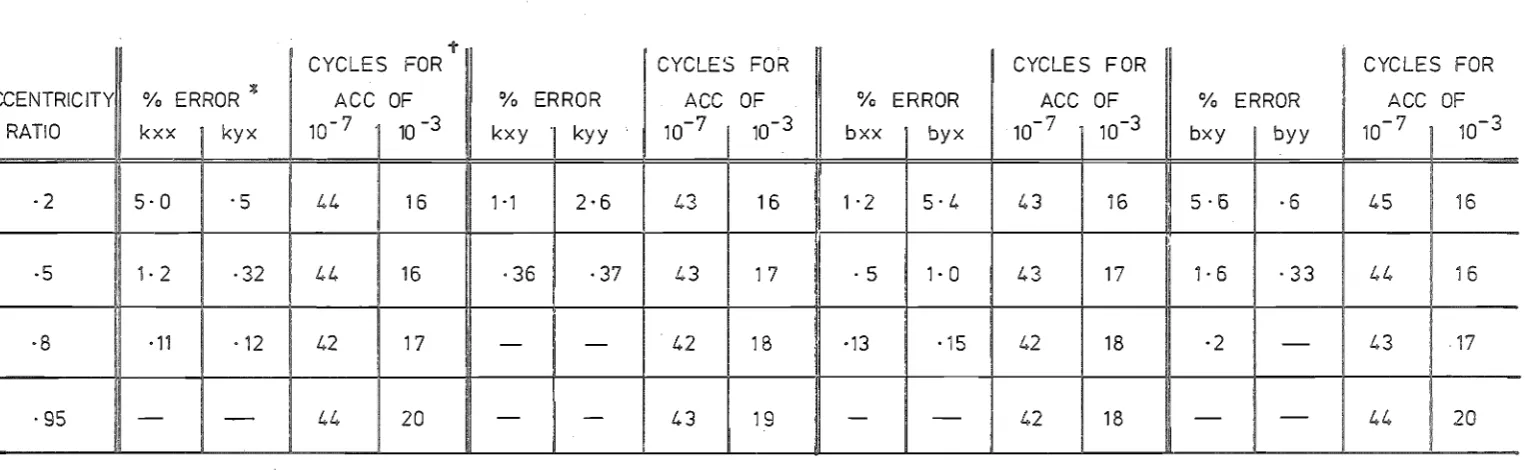
Two calculations were made at each journal velocity and displacement. The first with ACC set at 10-3 and the second at 10=7 to form a basis for the error calculations. The relaxation cycles required for each calculation and the percentage error in the coefficients are shown. The velocity coefficients, bxy and byx, for the squeeze film are not
shown as these are theoretically zero and thus error calculations would
RATIO kxx kyx 10- 7 10 -3 kxy
'I
kyy 10- 7 10- 3 bxx byx 10- 7 10-3 bxy byy·2 5·0 . 5 44 16 1 '1 2·6 43 16 1·2 5·4 43 16 5·6 ·6
·5 1· 2 ·32 1..4 16 ·36 ·37 43 1 7 ·5 1· 0 43 17 1·6 ·33
·8 ·11 ·12 42 17 -
-
42 18 ·13 ·15 42 18 ·2-·95 -
-
44 20-
-
43 19-
- 42 18 --
~-'" Percentage error based on va!ue of coeffient calculated with convergence tolerance
(ACC) of
-~
Errors less than 0 ,1%) shown as-.
t
No. of iteration cycles required to calculate the coefficients for convergence
tolerances (ACC) of
10-
7 and
10-
3.
10- 7 10-3
45 16
1..1.. 16
43 17
44 20
FIG.
2-5
EFFECT OF RELAXATION CONVERGENCE TOLERANCE ON THE ACCURACY AND NUMBER
OF CYCLES OF CALCULATION OF THE DYNA IC BEARING COEFFICIENTS.
UNIT
WEDGE OIL PRESSURE FILM.
W
[image:40.821.20.783.55.290.2]RATIO kxx kyx 10- 7 10- 3 kxy kyy 10- 7 3 bxx I byx 10- 7 10- 3 bxy byy 10- 7 10- 3
·7 1,6 42 15 2·4 ·12 38 14 44 15 1 ·3 4 15
-.5
·£.5 ·9 39 14 ,I."-
38 15 40 13 ·38 37 15,8 -
-
40 14 ·12-
38 16 '13 41 14-I
,95
-
-
42 17 ·14-
39 15-
42 15-
42
17-:t
Percentage error based on value of coefficient calculated
th convergence tolerance
(ACC} of 10- 7.
Errors
ss than 0·1%
shown as
+
iteration cycles
calculate the coefficie
con vergence
nces
ALL)
of
1 3
OF
o
LERANCE
E
N
BER
S OF
LCU
OF THE 0
C BEARING C
NTS.
IT
EEZE
IL PRESSU
L "
wThe choice of the tolerance was a compromise between accuracy and speed. The value, 10-3, gave good accuracies for eccentricities above 0.5 with computation times of half those for the pressure calculation. The errors increased as the eccentricity ratio was reduced, but they remained of the same order as the errors introduced by using the bearing coefficients in the locus marching procedure.
II.7 OIL FILM WORK
The stability of a rotating system is very much dependent on the behaviour of its bearings. The bearings provide a mechanism to excite or dampen the vibratory motion of the rotor, drawing energy from the rotation of the shaft. This is particularly important with hydro-dynamic bearings because the asymmetry of the oil pressure film enables considerable quantities of energy to be transferred.
There are three mechanisms of oil pressure film generation : (i) Hydrostatic: The pressure in the bearing grooves is
created by external pumping.
(ii) Wedge: This is the dragging of the oil into the con-verging film by the rotation of the journal. The film is modified by the an~ular velocity of the journal about the bearing centre.
(iii) Squeeze: A radial journal velocity produces a pressure film by forcing the oil out from between the closing journal and bearing surfaces.
about the eccentricity vector.
This film is symmetrical
.
RHS "" 6jl(e(w 2y) Sin (8 y) ~ 28 Cos (8
Wedge Squeez;e
The third term applies to non-circular geometries where the bearing segment centre and the co-ordinate system centre do not coincide.
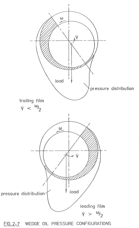
The effect of the journal centre angular velocity on the wedge film is clearly shown. For y
.
less than half the shaft speed, a trailing . film exists as depicted in Fig. 2-7. The oil film force has acom-ponent in the direction of the journal motion, provided the journal centre rotation is in the same direction as the shaft rotation, and energy is fed into the rotating system. Damping occurs if
y
>I
as a leadi~g film is formed.• W
The condition
y
= 2 is known as half speed whirl. The wedge film ceases to exist leaving the squeeze film to support the bearing load. Obviously a positive radial velocity cannot be maintained in-definitely and the journal collapses onto the bearing surface.Physically half speed whirl occurs when the velocity of the wedge is equal to the mean velocity of the carried flow. Continuity is sat-isfied at all points on the bearing surface, thus the mechanism of wedge film generation no longer exists.
The influence of the wedge film on the stability of a system is perhaps most clearly shown by the model in Figure 2-8. This model represents a light elastic shaft, stiffness 2Ks, with a central rotor mass 2Mr mounted in two identical light plain circular journal bearings. The system is depicted whirling about the bearing centre with angular
.
\
pressure distribution
-trail,ing
film
y
w'2
pressure d
load
leading film
y
w/
2
[image:44.569.54.511.35.785.2]Iy
_ - t - - - ! 1 '
oil film force on journal
x
FIG:
M
ROTOR MODEL;
SINGLE MASS
WORK ~ DEL.Sinl/J 21Tt:.
A force balance on the rotor mass can be achieved only with the addition of the force F. This may be applied as damping or by acceleration of the rotor. An elementary analysis of the system geometry will show that the energy dissipated in the damper, or added to the rotor, equals the pressure film work. Thus, the trailing film excites the rotor.
In general, the oil film work is too c('lmplex to assess analytically so numerical methods are required. The journal centre locus is marched out in time and the work increment calculated at each step
OWORK
=
-(FXJ + FXJ 1) OXj _ (FYJ + FYJ n_l)OYj
n n- 2 n 2
where FXJ .1FYJ 1 Journal load components at the beginning of
n-
n-FXJ ,FYJ
n n
8Xj,oYj
the nth step.
=
Journal load components at the end of thenth step.
=
Journal centre step.The force applied to the journal is used in this equation. In
.•• 2.7
marching out the journal locus the journal position and velocity at the end of a time step are estimated to achieve a force balance on the journal between the applied load and the oil film force (see 111.3). For each locus step errors are introduced into the work calculation the incorrect journal step and the incorrect forces resulting from calculating the film forces at a displacemen't and velocity containing the locus step error By using the applied journal load the latter is avoided, but this does not necessarily improve the accuracy of the calculation. F,or example, with a linear elastic system (Le. a
load was used for the work calculation instead of the calculated force, the accuracy for a step would improve, but not the calculation as a whole. Numerical experiments were conducted (see VI.I) and these showed no significant difference between the two methods of calculation for a wedge oil pressure film.
When calculating the oil film work the bearing can be loaded by the rotor or the latter can be represented by a force locus. Initially a circular force locus, that is, a constant magnitude vector rotating at constant speed with the possible addition of a static component, was used for this purpose, but ex~ept for a few cases, it was found to be inadequate. In general, even an undamped single mass rotor model was fou~d to be too complex to represent ~s a simple force locus. However, this technique is of benefit to assess the stability character-istics of a rotor bearing combination. This is discussed fully in Chapter 6.
The oil film subjects the journal to a viscous shear drag. Again, because of the film asymmetry, this affects the journal's transverse motion. The frictional force has two parts, one due to the pressure flow and the second to the carried flow. By considering the velocity profile, the shear force at any point on the journal surface is g
OSF
E..
[1!...
dP+
1:.J
2TIOx.oZ •• 2.8R 4TI H
If the x and y components of this are summed, the film asymmetry leaves a resultant force on the journal.
The effect of friction was not included in the analysis for two reasons :
Cameron, Akers and Michaelson(23) found that the friction was stabilizing although it was never found to transform an unstabl"e system to a stable one. Omission of friction thus errs on the side of safety.
(ii) The effect is small. The first term in Equation 2.8, the shear force due to the oil film pressure, can be integrated over the bearing surface to give the drag force for a wedge film in a plain circular bearing.
FORCE DEL =
r £
R 2 Sin l/J •
Derivation of this equation can be found in Cameron (24) . the magnitude of each term :
Thus:
Sin l/J < 1
£/2
<
.5r/R = 0 (.001)
r
R
£
2 . Sin l/J 0(.05%)
Consider
This is the total drag force arising from the pressure flow, thus any translational forces generated will be of equal or smaller magnitude.
yl
x
disrupted oil
film
VISCOUS SHEAR FORC
ON
THE JOURNAL
SURFACE AND THEIR RESULTANT
SFX
rr
27TE. Sin 27TX dX.dZR H
o
QSFY =:
rr
27TE. dX.dZ •. 2.9R H
o
0As none of the variables are functions of the axial displacement, Z, integratiOn in this direction is readily achieved. Before integration with respect to X can be performed, a number of assumptions are
necessary
(a) The bearing is circular and ungrooved. The film thickness is then :
H
=
I + € Cos 27TX.(b) The film is complete in the convergent section of the bearing, 0 < X < .5, but disrupts into streamers as the clearance increases. The aggregate width of the streamers,
£,
is obtained by applying flow continuity between the point of minimum film thickness, X=
.5, and a general pointx.
WR £ H ~R 1. (1 _ €)
1 - €
H
The integrals 2.9 bec.ome
SFX
:::::
f~
o27Tr Sin 2'ITX R
(l
2'ITr • dX + J~ R1-€ Sin2'ITX
(1+€Cos2'ITX) 2
dx
SFY ::::: (~ 2'ITr (-Cos2'ITX)
11
2'ITr (1-€) (-Cos27TX) , dxJ
o R 1+€Cos2'ITX· dx +
~
R (1+€Cos27TX) 2Evaluate the x component first. Substitute
SFX r
[rE~:+
t
l
£
l~E
-dB
1
=:
R HE: 1~E:
r
1 ( H £ 2
J
::::
-(E
l0ge 1-£] - H£ • RFor the y component the Sommerfeld substitution is required
Cos
S
£ + Cos 2TIX1 + e:;cos 2TIX Thus:
SFY == 2TIr
[(
1 1 dXR £ £ (l+£Cos2TIX)
[
1-£[
1III
+ - - - - dX
£ l+£Cos2TIX (1+ECos2TIX) 2
2~r
[L
I~
+ tTI l-E 1- l-ecO"f]dS]
::::
£R 2 (l_£2)i'~
0
=
TIr £RFrom these two components the resultant translational force arising from the carried flow can be calculated :
SF
These forces have been evaluated for a bearing of length to diameter ratio .75 and clearance ratio .001. The results, tabulated in Figure 2-10, show that the ratio of shear force to oil film force increases as the eccentricity ratio is lowered. The maximum value calculated was .32% at an eccentricity ratio of 0.1 thus the influence of the shear friction is small.
The values of the force components calculated were positive. Referr-ing to Figure 2-9, it can be seen that the translational force will,
E
0
.
·3
·5
·7
·9
·975
N CIRCULAR GEOMETRY.
DEL
~oSFX
SFY
SF
SF
~DEL
sin
l\J
DEL
0SFY
0
90
0
a
0
-
-. 51
80·7
·000171
·00
·000477
·32
335
·524
68·7
·00052
·0
·00136
·26
3
1 ·180
56·5
·00087
·00215
·00232
458
2·
·5
·00129
·00361
·00383
·13
554
25·2
·00139
·00793
·00805
·06
757
73·9
·7
·00349
.
83
·0186
956
.
. ,
I
I
I
I
;:;::.
whirl, thus reducing the damping effect of the oil pressure film.
The result for a trailing film agrees with the findings of Cameron, Akers and Michaelson. However, it is not clear in their paper what effect friction had on a stable system and thus a comparison for a leading film cannot be made.
The vlork performed by the oil film on the journal for a constant speed, constant amplitude journal centre whirl is given by
~'lORK 2'IT£ (DEL.Sinl/J - SFY).
The choice of axes for the calculation of the shear force components was such that SFY is perpendicular to the journal eccentricity vector. For the shear force to render the system stable :
or
SFY > DEL. Sin l/J
DEL. Sin
SFY < 1
The value of this ratio is also tabulated in Figure 2-10. It far from satisfies the inequality thus agreeing with the observation of
Cameron, Akers and Michaelson that the effect of friction never trans-formed an unstable system to a stable one.
From this elementary investigation it is apparent that the trans-lational force resulting from the viscous shear drag of the oil film on the journal is small compared to the oil pressure force. Although this force affects the stability of a bearing-rotor system, the work of Cameron, Akers and Michaelson(23) and the calculations presented here
CHAPTER THREE
COMPUTER PROGRAM
In this chapter the program to analyse a dynamically loaded
bearing is described. The first section considers the general layout of the program and describes briefly its function and capabilities. This is followed by three sections describing the system used to define the bearing surface geometry and the techniques employed to march out the journal and rotor loci.
111.1 GENERAL DESCRIPTION
The program has two major tasks. The first is to march out the journal centre locus when the bearing is subjected to a load that is dependent. The second is to calculate the work done by the oil film force on the journal as the journal moves around this locus.
There are two basic variants of the program, the difference arising from the method of loading the bearing. In the first the journal is loaded directly by a predetermined force locus. This consists of a stationary force plus a constant magnitude force vector rotating at a constant angular velocity. These forces represent the static and dynamic loads transmitted to the bearing through the rotor shaft. The validity of assuming the dynamic load to take this form is discussed in Chapter 6.
The program was written to handle a wide variety of bearing designs. The cross-sectional shape of the bearing is defined by up to three
circular arcs thus allowing designs such as elliptical, spiral and three lobe to be considered. Provision has also been made for a comprehens-ive pattern of grooves which may be pressurised
Apart from the locus stepping section the flow diagrams for the programs are very similar. A simplified diagram is sho\~ in Fig. 3-1 and a complete source listing for the directly loaded journal program is given in the Appendix together with a brief summary of the role of each subroutine.
At the begin~ing of the main loop, Fig. 3-1, the minimum oil film thickness is calculated and checked to ensure the journal is within the bearing clearance. Reynolds equation is then solved, as described in Chapter 2, and the pressure distributions summed to obtain the oil film forces. The accuracy of each locus step is assessed by checking the force balance on the journal. The time increment for the next step is adjusted according to this check or, if the accuracy is sufficiently poor, the step repeated with a reduced time increment.
The work performed by the oil film on the journal is calculated at this stage using Equation 2.7
I Data Input I
Bearing geometry definition
Calculate minimum
oil film thickness
Relax pressure film Calculate film forces
I
Accuracy check: compare AccuracyI
film force to journal load UnsatisfactoryAdjust locus time step length Reduce step length
Repeat step
I
Calcu late oil film workI
Calcu late dynamic
bearing coefficients
Estima te mean coeffl cie n ts
for next locus step
IOutput I
Is
locus Yes I
~
I Stop
complete
No
Calcu late locus s te p
I
The program for the directly loaded journal is halted after two cycles of the rotating load. The first of these is required to remove the transients introduced by the starting conditions. If the program incorporates a rotor model it can be terminated after any nwnber of load cycles or when a specified computation time has elapsed.
I I I • 2 BEARING GEOI1ETRY
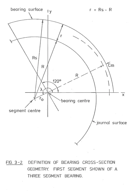
The bearing cross-sectional geometry is defined as a series of circular a::s.:cs. Up to three of these segments can be used, but they must subtend equal angles at t,he bearing centre and together make up a complete 3600 bearing. The first segment of a three land bearing is shown in Fig. 3-2 with the journal positioned at the centre of the segment. The radial clearance, r, is the difference between the segment and journal radii. The clearance space is the area remaining within the segment when the journal radius is reduced to zero. This is a convenient way to show the journal position and bearing surface together. If the bearing was drawn to scale the bearing clearance ,.,ould be imperceptible because the clearance ra"tio r/R is of the order of .001. The clearance space is used in later chapters to bound the journal locus. It does not, however, necessarily form the limit of possible journal movement.
The minimum clearance of the segment, em, is the minimum film thickness when the journal is at the bearing centre. The value of this parameter for the final segment, that is, the third segment for a three land bearing, is used to non-dimensionalize the system's variables