Network Performance of Asynchronous UTRA-like FDD/CDMA Systems using
Loosely Synchronised Spreading Codes
Song Ni, Hua Wei, Jonathan S. Blogh, Lajos Hanzo
Dept. of Electronics and Computer Science, Univ. of Southampton, SO17 1BJ, UK.
Tel: +44-(0)23-8059-3125, Fax: +44-(0)23-8059-4508
Email:
lh
@ecs.soton.ac.uk http://www-mobile.ecs.soton.ac.uk
Abstract
In this paper we characterize the capacity of a UTRA-like Frquency Division Duplex (FDD) Code Division Multiple Access (CDMA) system employing Loosely Synchronized (LS) spreading codes. Current CDMA systems are inter-ference limited, suffering from Inter-Symbol-Interinter-ference (ISI), since the orthogonality of the spreading sequences is destroyed by the channel. They also suffer from Multiple-Access-Interference (MAI) owing to the non-zero cross- cor-relations of the spreading codes. LS codes exhibit a so-called Interference Free Window (IFW) , where both the auto-correlation and cross-correlation of the codes become zero. Therefore LS codes have the promise of mitigating the effects of both ISI and MAI in time dispersive chan-nels. Hence, LS codes have the potential of increasing the capacity of CDMA networks. This contribution studies the achievable network performance by simulation and com-pares it to that of a UTRA-like FDD/CDMA system us-ing Orthogonal Variable Rate Spreadus-ing Factor (OVSF) codes.
1. INTRODUCTION
In our previous research [1, 2, 3], the performance of a UTRA-like FDD CDMA system was quantified, when supported by adaptive beam-steering and adaptive modulation [4]. In [3], the system employed OVSF spreading codes [5], which offer the benefit of perfect orthogonality in an ideal channel. In a non-dispersive channel, all intracell users’ signals are perfectly orthogonal. However, upon propagating through a dispersive multipath channel this orthogonality is eroded, hence all other users will interfere with the desired signal. Therefore in prac-tice the intra-cell interference is always non-zero.
In this contribution, we will consider the employment of a specific family of spreading codes, which are known as Loosely Synchronized (LS) codes [6]. These codes exhibit a so-called Interference Free Window (IFW), where the off-peak aperiodic autocorrelation values as well as the aperiodic cross-correlation values become zero, resulting in zero ISI and zero MAI, pro-vided that the delayed asynchronous transmissions arrive within
The financial support of the European Union under the auspices of the SCOUT project is gratefully acknowledged.
the IFW. More specifically, interference-free CDMA commu-nications become possible, when the total time offset expressed in terms of the number of chip intervals, which is the sum of the time-offset of the mobiles plus the maximum channel-induced delay spread is within the code’s IFW [7]. By employing this specific family of codes, we are capable of reducing the ISI and MAI, since users in the same cell do not interference with each other, as a benefit of the IFW provided by the LS codes used.
The outline of this paper is as follows. Firstly, we briefly focus our attention on the design of LS codes in the next sec-tion. Section 3 introduces the system parameters, leading to a discussion on the performance metrics employed in Section 4. The system performance benefits of using LS codes in a pedes-trian scenario are quantified in Section 5 and we conclude our discussions in Section 6 .
2. LOOSELY SYNCHRONIZED CODES
There exists a specific family of LS codes [6], which exhibits an IFW. Specifically, LS codes exploit the properties of the so-called orthogonal complementary sets [6, 8]. To expound further, let us introduce the notation of LS for
de-noting the family of LS codes generated by applying a (
)-dimensional Walsh-Hadamard matrix to an orthogonal com-plementary code set of length , while inserting number
of zeros in the centre and at the beginning of the LS code, as shown in Figure 1, using the procedure described in [6]. Then, the total length of the LS code is given by
and the number of codes available is given by
.
Complementary Pair Complementary Pair
W0 W0
Figure 1: The LS code structure.
Since the construction method of binary LS codes was de-scribed in [6], we will focus our attention on the employment of orthogonal complementary sets [9, 10] for the generation of LS codes. Firstly, we define a sequence set ,
where !#"$ % is a spreading sequence
hav-ing a length of& . These spreading codes exhibit an IFW width
mod ! #" ! %$%& &' IFW ( (1) The aperiodic correlation
# of two sequences)
and
)
has to satisfy Equation 1 for the sake of maintaining an IFW of IFWchip intervals.
For a given complementary pair* + , - of length , one
of the corresponding mate pairs can be written as * +
,
- ,
where we have:
+
/.
, 0 (2)
,
213.
+ 0 (3)
and where.
, denotes the reverse-ordered sequence, while
1
,
is the negated version of, , respectively. Note that in (2) and
(3) additional complex conjugation of the polyphase comple-mentary sequences is required for deriving the corresponding mate pair in comparison to binary complementary sequences [6]. Having obtained a complementary pair and its corresponding mate pair, we may employ the construction method of [6] for generating a family of LS codes. The LS codes generated ex-hibit an IFW, where we have
for&
& '54768 *
1
- . Hence, we may adopt a choice of
1
in order to minimize the total length of the LS codes generated, while providing as long an IFW as possible.
For example, the LS(4,2,3) codes can be generated based on the complementary pair of [9]:
+ 1 (4) , 11 ( (5)
Upon substituting (2) and (3) into (4) and (5), the correspond-ing mate pair can be obtained as:
+ 9. , 0 1 (6) , /13. + 0 1:11 ( (7) g g g g
W0 c0 s0 W0 c1 s1
−
c1
s1
−c1
s1 s1 c1 − c0 s0
−c0
[image:2.595.311.544.99.197.2]s0 c0 0 s 0 1 2 3
Figure 2: Generating four LS codes
The generation of this set of the four LS codes can be viewed in Fig 2. Upon invoking the
-dimensional Hadamard expansion of [6] in the context of the above orthogonal com-plementary pairs, we can generate a family of four LS(4,2,3) codes, which are denoted by); ,<
=
> > > ? .
All four different codes of the LS(4,2,3) code family ex-hibited the same autocorrelation magnitudes, namely that seen in Figure 3(a). It can be observed in Figure 3(a) that the off-peak autocorrelation ; @ A becomes zero for
&
& '
? . The
0 10 20
[image:2.595.51.291.511.629.2]30-30 -20 -10 0 10 20 30
|Autocorrelation| offsets[chip] (a) Autocorrelation 0 10 20
30-30 -20 -10 0 10 20 30
|Crosscorrelation|
offsets[chip]
(b) Crosscorrelations
Figure 3: correlation magnitudes of the LSBC# D E F codes. (a)
All four codes exhibit the same autocorrelation magnitude. (b) The crosscorrelation magnitudes ofG# andGH .
crosscorrelation magnitudesIJK L B'F I depicted in Figure 3(b)
are also zero forI' I MON $7E . Based on the observations made
as regards to the aperiodic correlations we may conclude that the LS(4,2,3) codes exhibit an IFW ofPQE chip durations.
3. SYSTEM PARAMETERS
New call channel allocation requests were placed in a resource allocation queue for up to 5s. If during this period a call was not serviced, it was classed as blocked. The mobiles moved freely, in random directions, at a speed of 30mph within the simulation area, which consisted of 49 cells. The cell-radius was 86.8 m, which was the maximum affordable cell radius for the IFW duration ofPQE chip intervals at a chip rate of 3.84
Mchip/s. The call duration and inter-call periods were Poisson distributed with the mean values shown in Table 1. For our initial investigations we have assumed that the basestations and mobiles form a synchronous network.
Furthermore, the post-despreading SINRs required for ob-taining the target BERs were determined with the aid of physical-layer simulations using a 4-QAM modulation scheme, in con-junction with 1/2-rate turbo coding for transmission over a COST 207 seven-path Bad Urban channel [11]. Using this turbo-coded transceiver and LS codes having a spreading fac-tor (SF) of 16, the post-despreading SINR required for main-taining the target BER ofRSQR T
"U
was 6.2 dB. The BER which was deemed to correspond to low-quality access, was stipu-lated atVOS:R T
"U
. This BER was exceeded for SINRs falling below 5.2 dB. Furthermore, a low-quality outage was declared, when the BER ofRSR T
"H
was exceeded, which was encoun-tered for SINRs below 4.8 dB. These values can be seen along with the other system parameters in Table 1.
4. PERFORMANCE METRICS
There are several performance metrics that can be used for quantifying the performance or quality of service provided by a mobile cellular network. The following performance metrics have been widely used in the literature and were also advocated by Chuang [13]:
W
New call blocking probability,XZY .
W
Call dropping or forced termination probability,XZ[\ . A
down-Parameter Value Parameter Value
Noisefloor -100dBm Pilot power -8.5dBm
Frame length 10ms Cell radius 86.8m
Multiple access FDD/CDMA Number of basestations 49
Modulation scheme 4QAM/QPSK Spreading factor 16
Min BS transmit power -47.5dBm Min MS transmit power -47.5dBm
Max BS transmit power 17.5dBm Max MS transmit power 17.5dBm
Power control stepsize 1dB Power control hysteresis 1dB
Low quality access SINR 5.2dB Outage (1% BER) SINR 4.8dB
Pathloss exponent -2.0 Size of Active BS Set (ABS) 2
Average inter-call-time 300s Max. new-call queue-time 5s
Average call length 60s Pedestrian speed 3mph
Max consecutive outages 5 Signal bandwidth 5MHz
[image:3.595.117.480.98.262.2]Target SINR 6.2dB
Table 1: Simulation parameters.
link SINRs dips consecutively below the outage SINR (1% BER) a given number of times.
Probability of a low quality access,
, quantifies the
chances of either the uplink or downlink signal quality being sufficiently poor, resulting in a low quality access (0.5% BER).
Probability of outage,
, is defined as the probability
that the SINR is below the value at which the call is deemed to be in outage, namely below 4.8 dB, as seen in Table 1.
Grade-Of-Service (GOS) was defined by Cheng and Chuang [13] as :
Our network performance studies were conducted with aim of maintaining:
'
3%, '
1%,
'
1% and GOS
'
4%.
5. SIMULATION RESULTS
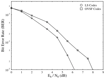
Our current research is building on our previous findings recorded in the context of a UTRA-like FDD system [1], where we found that invoking adaptive modulation as well as beam-steering proved to be a powerful means of enhancing the capacity of FDD/CDMA. In the investigations of [1], OVSF codes were used as spreading codes. However, the intracell interference is only eliminated by employing orthorgonal OVSF codes, if the system is perfectly synchronous and provided that the mo-bile channel does not destroy the OVSF codes’ orthogonality. In an effort to prevent intracell interference, again, in this pa-per we employ LS codes, which exhibit ideal auto-correlation and cross-correlation functions within the IFW. Thereby, the “near far effect” may be significantly reduced and hence the user capacity of the system can be substantially enhanced. Fig-ure 4 compares the BER performance of OVSF codes and LS codes, which were determined with the aid of physical-layer simulations using a 4-QAM modulation scheme, 1/2-rate turbo coding and a Minimum Mean Squared Error Block Decision Feedback Equaliser (MMSE-BDFE) based Multi-User Detec-tor (MUD) [12] joint detection for transmission over a COST
207 seven-path Bad Urban channel [11]. The figure illustrates that the achievable BER performance of LS codes is better than that of OVSF codes. For a spreading factor of 16, the post-despreading SINR required for maintaining a BER of
was 6.2 dB in case of LS codes, which is almost 2 dB lower than that necessitated by the OVSF codes.
0 1 2 3 4 5 6 7 8 9
Eb/ N0(dB)
10-3
2 5
10-2
2 5
10-1
2
Bit
Error
Rate
(BER)
[image:3.595.323.532.389.547.2]OVSF Codes LS Codes
Figure 4: BER performance of a UTRA-like system using OVSF codes and LS codes generated with the aid of physical-layer simulations using 4-QAM modulation, 1/2-rate turbo coding and MMSE-BDFE joint detection for transmissions over a COST 207 seven-path Bad Urban channel.
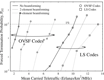
Figure 5 shows the call dropping probability associated with a variety of traffic loads measured in terms of the mean normalized carried traffic expressed in Erlangs/kmH
/MHz when subjected to 0.5 Hz frequency shadowing having a standard de-viation of 3 dB. The figure illustrates that the network’s perfor-mance was significantly improved by using LS codes. In con-junction with OVSF codes, the “No beamforming” scenario suffered from the highest call dropping probability of the six traffic scenarios at a given load. Specifically, the network ca-pacity was limited to 152 users, or to a teletraffic load of ap-proximately 2.65 Erlangs/kmH
em-2 4 6 8 10 12 14
Mean Carried Teletraffic (Erlangs/km2/MHz)
10-3
2 5
10-2
2
Forced
Termination
Probability
,P
FT
OVSF Codes
LS Codes 1%
4-element beamforming 2-element beamforming No beamforming
[image:4.595.63.271.107.267.2]LS Codes OVSF Codes
Figure 5: Call dropping probability versus mean carried traf-fic of the UTRA-like FDD cellular network usingLS codes and OVSF codesboth with as well as without beamforming in conjunction with shadowing having a frequency of 0.5 Hz and a standard deviation of 3dB for a spreading factor of SF=16.
ploying four-element adaptive antenna arrays at the base sta-tions the number of users supported by the network increased to 428 users, or almost to 7.23 Erlangs/kmH
/MHz. However, in conjunction with LS codes, and even without employing an-tenna arrays at the base stations the network capacity was dra-matically increased to 581 users, or 10.10 Erlangs/kmH
/MHz. When four-element adaptive antenna arrays was employed in LS codes scenario, the system could support 800 users, and equal to a teletraffic load of 13.3916 Erlang/kmH
/MHz. This is because the LS codes’ perfect auto-correlation and cross-correlation functions essentially eliminated the intracell inter-ference, as it was discussed in Sections 1 and 2.
2 4 6 8 10 12 14
Mean Carried Teletraffic (Erlangs/km2/MHz)
10-4 2 5
10-3 2 5
10-2
2
Probability
of
low
quality
access,
Plow
OVSF Codes
LS Codes 1% 4-element beamforming
2-element beamforming No beamforming
LS Codes OVSF Codes
Figure 6: Probability of low quality access versus number of users of the UTRA-like FDD cellular network usingLS codes and OVSF codesboth with as well as without beamforming in conjunction with shadowing having a frequency of 0.5 and a standard deviation of 3dB for a spreading factor of SF=16.
The probability of low quality access is depicted in Fig-ure 6. As expected, a givenX value was associated with
[image:4.595.323.533.446.605.2]a higher traffic load, when the number of antenna elements was increased. In the case of OVSF codes, it can be seen from the figure that without beamforming the system suffered more interference as the traffic loads increased, the probabil-ity of low qualprobabil-ity access became higher. In conjunction with beamforming, intra- and inter-interference was reduced suffi-ciently, the probability of low quality reduced as well. How-ever, increasing the number of antenna elements from two to four results in an increased probability of a low quality out-age owing to the sharper antenna directivity. As a benefit of employing LS codes, the intra-interference was eliminated ef-ficiently, the probability of low quality access was found to be lower even without beamforming, than that of the system us-ing OVSF codes and employus-ing 2- or 4-element beamformus-ing. Again, owing to the sharper antenna directivity, the probability of a low quality outage increased while increasing the number of antenna elements from two to four. It should be noted that the probability of low quality access always remained below our 1% constraint in the scenarios studied.
Figure 7 shows the achievable Grade-Of Service (GOS) for a range of teletraffic loads. Similar trends were observed regarding the probability of low quality access to those shown in Figure 6. The grade of service is better (i.e. lower) when the traffic load is low, and vice versa for high traffic loads. This is mainly attributable to the higher call blocking probability of the “No beamforming” scenario, particularly in the region of the highest traffic loads.
2 4 6 8 10 12 14
Mean Carried Teletraffic (Erlangs/km2/MHz)
10-4 2 5
10-3
2 5
10-2
2
Grade
of
Service
(GOS)
OVSF Codes
LS Codes 1% 4-element beamforming
2-element beamforming No beamforming
[image:4.595.62.271.513.673.2]LS Codes OVSF Codes
Figure 7: Grade-Of-Service (GOS) versus number of users of the UTRA-like FDD cellular network usingLS codes and OVSF codesboth with as well as without beamforming in con-junction with shadowing having a frequency of 0.5 Hz and a standard deviation of 3dB for a spreading factor of SF=16.
Traffic (Erlangs Power (dBm)
Spreading Code Beamforming Users /km /MHz) MS BS
OVSF codes No 152 2.65 -9.0 -9.0
OVSF codes 2-elements 242 4.12 -8.28 -7.88
OVSF codes 4-elements 428 7.23 -7.45 -5.40
LS codes No 581 10.1 -8.19 -5.84
LS codes 2-elements 622 10.6 -9.88 -5.53
[image:5.595.134.463.97.197.2]LS codes 4-elements 802 13.39 -10.57 -4.49
Table 2: Maximum mean carried traffic and maximum number of mobile users that can be supported by the network, whilst meeting the network quality constraints of Section 4, namely
'
3%, '
1%,
'
1% and GOS '
4%. The carried traffic is expressed in terms of normalized Erlangs (Erlang/km /MHz) usingOVSF codes and LS codesin conjunction with shadow fading having a standard deviation of 3 dB and a frequency of 0.5 Hz, whilst employing adaptive modulation techniques [11] for a spreading factor of SF=16.
2 4 6 8 10 12 14
Mean Carried Teletraffic (Erlangs/km2/MHz)
-13 -12 -11 -10 -9 -8 -7 -6 -5 -4
Mean
T
ransmission
Power
(dBm)
OVSF Codes
LS Codes 4 element beamforming
2 element beamforming No beamforming
Filled = Downlink, Blank = Uplink
LS Codes OVSF Codes
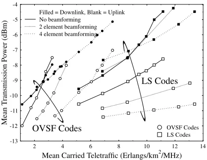
Figure 8: Mean transmission power versus number of users of the UTRA-like FDD cellular network usingLS codes and OVSF codesboth with as well as without beamforming in con-junction with shadowing having a frequency of 0.5 Hz and a standard deviation of 3dB for a spreading factor of SF=16.
to maximise the received SINR, and thus the levels of inter-ference are attenuated efficiently. Invoking adaptive antenna arrays at the basestation reduced the mean uplink tranmission power required to meet the service quality targets of network. In OVSF codes scenarios, the basestation suffered more in-terference as the traffic loads increased, especially the intra-interference, which resulted uplink mean transmission power had to be increased to reach the target SINR. However, the LS codes eliminated the intra-interference superiorly, reduced the levels of interference, ultimately leading to the reduction of the mean transmission.
A summary of the maximum user capacities of the UTRA-like networks using OVSF codes and LS codes in conjunction with log-normal shadowing having a standard deviation of 3 dB and a frequency of 0.5 Hz, both with and without employ-ing beamformemploy-ing is given in Table 2. The teletraffic carried and the mean mobile and base station transmission powers re-quired are also shown in Table 2.
6. SUMMARY AND CONCLUSIONS
It was demonstrated that the network performance of UTRA-like system employing LS spreading codes was substantially better than that of the system using OVSF codes. Explicitly, a low dropping probability, low mobile and base station trans-mission power and high call quality has been maintained. In the context of the interference limited 3G CDMA system LS codes [7] might hold the promise of an increased network ca-pacity without dramatic changes of the 3G standards. Our fu-ture research will focus on studying Large Area Synchronised (LAS) codes in conjunction with adaptive antenna arrays [1] and adaptive modulation techniques [4].
7. REFERENCES
[1] J.S. Blogh, L. Hanzo: Third-Generation Systems and Intelligent Wireless Networking - Smart An-tennas and Adaptive Modulation, John Wiley and IEEE PRESS, 2002
[2] J. S. Blogh, L. Hanzo, “The Network Performance of Multi-Rate FDD-Mode UMTS”, IEEE VTC’01 Fall, Atlantic City, USA, October, 2001, pp 1294-1298
[3] J. S. Blogh, L. Hanzo, “Adaptive Antenna Assisted Network Performance of FDD-Mode UMTS”, IEEE VTC’01 Spring, Rhodes, Greece, May, 2001, pp 2455-2459
[4] L. Hanzo, C.H. Wong, M.S. Yee: Adaptive wireless transceivers: Turbo-Coded, Turbo-Equalised and Space-Time Coded TDMA, CDMA and OFDM systems, John Wiley and IEEE PRESS, 2002, pp 737
[5] F. Adachi, M. Sawahashi, K. Okawa, “Tree-structured Generation of Orthogonal Spreading Codes with Different Lengths for Forward Link of DS-CDMA Mobile”, Electronics Letters, Vol.33, No.1, pp 27-28, 1997
[6] S. Sta´nczak and H. Boche and M. Haardt, “Are LAS-codes a miracle?”, GLOBECOM ’01, Vol. 1, pp 589-593, San Antonio, Texas, November 2001
[7] D. Li, “A high spectrum efficient multiple access code”, Chinese Journal of Electronics, Vol. 8, pp 221-226, July 1999
[8] C.-C. Tseng and C. L. Liu, “Complementary Sets of Sequences”,IEEE Transactions on Information Theory, Vol.18, No.5, pp 644-652, Sep. 1972
[9] R. L. Frank, “Polyphase Complementary Codes”, IEEE Transactions on Information Theory, Vol.26, No.6, pp 641-647, Nov. 1980
[10] R. Sivaswamy, “Multiphase Complementary Codes”, IEEE Transactions on Information Theory, Vol.24, No.5, pp 546-552, Sep. 1987
[11] L. Hanzo, L.L. Yang, E. L. Kuan and K. Yen: Single- and Multi-carrier CDMA, John Wiley and IEEE Press, to appear.
[12] S. Verd´u,Multiuser Detection. Cambridge University Press, 1998.
[image:5.595.63.272.291.453.2]