TECHNOLOGY, INC.
165 FREEDOM AVE.
ANAHEIM
JCALIFORNIA·
92801
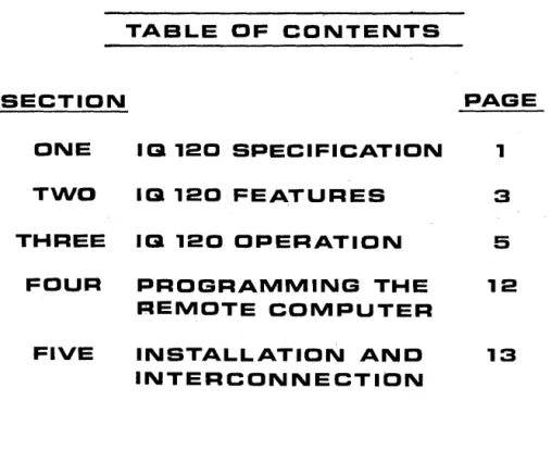
TABLE OF CONTENTS
SECTION
PAGE
ONE
113 120 SPECIFICATION
1
TWO
113 120 FEATURES
3
THREE
113 120 OPERATION
5
FOUR
PROGRAMMING THE
12
REMOTE COMPUTER
FIVE
INSTALLATION AND
13
SECTION ONE IQ 120 SPECIFICATION DISPLAY FORMAT
Standard-1920 characters arranged in 24 horizontal lines, 80 characters per line.
SCREEN
Rectangular CRT, 12 inches diagonal, P4 phosphor
DISPLAY MEMORY
1920-character (8-bit) MOS RAM memory
CHARACTER SET
96 alphanumeric ASCII characters
DISPLAY REFRESH RATE
50 or 60 Hz
CURSOR
Forespace, backspace, upline, downline, new line, return, home, tab, and absolute cursor addressing.
FIELD PROTECTION
Any part of the display can be designated as protected to prevent inadvertent overtyping.
Pro~ected fields are displayed at reduced intensity.
TRANSMISSION MODES
Conversation mode (full or half-duplex)-characters transmitted as they are typed. Block mode-unprotected, transmit line or page.
KEYBOARD
73-Keys including numeric pad
EDITING FEATURES
Standard-Clear screen, type-over, and absolute cursor addressing. Erase to end of page, erase to end of line/field
REPEAT
15 cps auto repeat
PARITY GENERATION
INTERFACE
RS 232-C Point to Point
DATA RATES
Switch selectable: 75, 110, 150, 300, 600, 1000, 1200, 1800, 2000, 2400, 3600, 4800, 7200, 9600, and 19200.
DIMENSIONS
12.5" high, 18" wide, 21" deep
WEIGHT
45 Pounds
POWER REQUIREMENTS
115 Vac, 60 Hz, 130 watts
OPERATING ENVIRONMENT
SECTION TWO IQ 120 FEATURES
SELECTABLE TRANSMISSION RATES
To meet the varied transmission rate requirements of a variety of computer interfaces, tele-phone data lines, and modems, the 10 120 can operate at data rates of 75, 110, 150,300, 600, 1000, 1200, 1800, 2000, 2400, 3600, 4800, 7200, 9600 or 19200 baud. The operator can select any speed at a switch on the rear of the 10 120.
MODES OF OPERATION
Conversation Mode, Half-Duplex. In this mode, the 10 120 can send and receive informa-tion to and from the remote computer, but in only one direcinforma-tion at a time. Characters are dis-played and simultaneously transmitted one character at a time as they are typed at the keyboard. Received characters are displayed as they are received.
Conversation Mode, Full-Duplex. Characters are transmitted as they are typed but are dis-played only on reception. Display of characters typed in full-duplex is usually accol)1plished by the remote computer or the modem echoing the characters back to the 10 120.
FIG.l
Roll Mode. 10 120 is in the roll mode while in full or half-duplex operation with the display unprotected. Executing a line advance function from the bottom line of the screen causes the entire display to move up one line, leaving a new blank line atthe bottom. The top line is lost.
In addition to the edit capability, the block mode provides faster transmission of large blocks of data than does the conversation mode. It also permits more efficient utilization of the remote computer and data transmission lines for many applications.
MODE SELECTION
A switch on the rear of the IQ 120 allows the operator to change between full-duplex, half-duplex, and block modes.
THE CURSOR
The cursor is a bright rectangular marker on the 10 120 screen which indicates the entry point for the next character typed. As characters are entered, the cursor moves from left to right across the display. When the cursor is positioned over a character already displayed" on the screen, the character appears as a reverse image in the cursor. Cursor positioning can be controlled from the keyboard or the remote computer.
Incremental Cursor Control. The cursor can be moved up, down, left or right incrementally by the keyboard or the remote computer.
Absolute Cursor Addressing. The cursor can be positioned using an absolute address , which contains the X and Y co-ordinate location.
EDIT CAPABILITIES
The standard 10 120 allows the following capabilities for information editing: Character Type-over
Clear Unprotected Positions to Nulls Clear Entire Screen to Nulls Erase to end of Line/Field Erase to end of Page
FIELD PROTECTION
Areas on the IQ 120 display can be designated by the operator or the remote computer as protected fields. These fields appear at a lower brightness level than the rest of the display and have several useful characteristics:
Protected areas cannot be typed over unless the terminal is first removed from the protected mode. This prevents inadvertent over-typing.
Protected areas are not transmitted by IQ 120.
HOME KEY
SECTION THREE IQ 120 OPERATION
This key causes the cursor to return immediately to the first character position of the first line (called home position). If the 10 120 is in the protected mode and the home position is a protected character, the cursor will be positioned to the first unprotected position on the screen.
RETURN KEY
This key causes the cursor to move to the first character position of the present line, or to the first unprotected position of the present line if the 10 120 is in the protected mode.
ALPHA KEY
This alternate action key, when locked down, shifts the 26 alphabetic keys in the upper case mode. All other keys are unaffected.
~KEYS
These keys move the cursor one character position in th-e direction of the arrow. If the 10 120 is in the protected mode and the adjacent position in the direction of the arrow is pro-tected, the cursor will skip the entire protected field and stop at the first unprotected poSition. The forespace and backspace operations may also be accomplished with the CTRL/L and CTRL/H functions.
t
KEYSThis key moves the cursor straight up one line. If the 10 120 is in the protected mode and the position directly above the cursor is protected, the cursor will move up and then to the left from that position to the first unprotected position. This function may also be accom-plished with the CTRL/K keys .
. . KEYS
This key is identical in function to the LINE FEED key. This function may also be accom-plished using the CTRL/J keys.
TAB KEY
In the protected mode, this key causes the cursor to move to the first unprotected character position following the next protected field. If there are no protected fields between the cursor and the end of the screen, the cursor goes to home or to the first unprotected pOSition. This function may also be accomplished using the CTRL/I keys.
RUB KEY
SPACE BAR
Pressing the space bar causes an ASCII space code to be stored in the display memory and a blank space to appear on the screen.
SHIFT KEY
This key is depressed to type the character marked in the upper portion of the typing key.
CLR KEY
This key clears the display and stores null codes in the display memory.
CTRL KEY
This key, when held down while typing another key which generates a transmittable code, causes the bit pattern of the character code to be modified. The control character is trans-mitted in conversation mode.
Ne\v Line. (CTRL/Underline). Positions the cursor to the first character position of the next line (the first unprotected position if in the protected mode).
Beep (CTRUG). Sounds the audible beep in the 10 120.
ESC KEY
When the escape key is operated with the shift key in full duplex mode an ASCII escape code is transmitted to the line. When the escape key is operated along with shift code in half duplex an ASCII escape code is sent to the line and causes the next character to be interpreted as the second code in one of the escape sequences described below.
When the escape key is operated when the terminal is in block mode no character is sent to the line but the next character typed is interpreted as the second code in an escape sequence.
Set Protect Mode (ESC &). Sets the 10 120 into the protected mode, preventing the cursor from entering any position containing a character previously designated as protected. When an (ESC &) is issued to the 10 120 the cursor is set to the home position. If the home position is protected the cursor is moved to the first unprotected position after the home position.
Reset Protect Mode (ESC '). Set the 10 120 into the unprotected mode allowing the cursor to enter and overtype protected areas. The protectable status of previously protected char-acters is maintained; such charchar-acters will again become protected when the display is returned to the protected mode.
Start Write Protect (ESC) ). Sets the 10 120 into the Write Protect mode and deSignates all characters typed thereafter as protectable.
End Write Protect (ESC (). Removes the 10120 from the Write Protect mode so all charac-ters typed thereafter are unprotected.
Send Page Unprotected (ESC 4). The unprotected character positions from the beginning of the current line through the cursor position is transmitted to the remote computer. The last character position transmitted is followed by transmission of a RETURN code.
Send Page Unprotected (ESC 5). The unprotected character positions from the begin-ning of the page through the cursor is transmitted to the remote computer. The last character position transmitted is followed by transmission of a RETURN code.
Transmission of null codes to the remote computer is always suppressed by the IQ 120.
Disable Keyboard (ESC #). Disables the keyboard functions.
Enable Keyboard (ESC "). Enables the keyboard functions, when issued by the remote computer, locally only the CLEAR key can remove the keyboard from a disabled condition.
Load Cursor (ESC =). The next two characters following the ESC = sequence represent the absolute cursor row and column coordinates respectively. The cursor coordinate ASCII codes are listed on page 13.
Auxiliary Port on (ESC @). Enable data received on the communications interface to be transmitted through the auxiliary port.
Auxiliary Port off (ESC A). Disables transmission over the auxiliary port.
Clear Display of Nulls (ESC *). Clears entire display to unprotected null codes, and sets unprotected mode.
Clear Unprotected Display to Nulls (ESC +). Stores unprotected nulls in all unprotected locations on the screen. Does not change protect mode. If unprotected mode was set, clear the entire screen to spaces.
IB12D
KEYBOARD
IQ 120 CONTROLS
Besides the keyboard, the only manual controls are located on the rear of the 10 120. These controls are described as follows: (Fig. 3)
ON/OFF SWITCH
This two-position switch controls the AC power to the unit and certain up and power-down sequences. Setting the switch to the ON position resets the circuitry within the 10 120
positions the cursor to home, and clears the display memory to unprotected nulls.
BRIGHTNESS CONTROL
This potentiometer controls the overall brightness of the CRT display. Brightness is usu-. ally adjusted so the display raster (background) is barely visible or just below the point of
visibility .
. CONTRAST CONTROL
This potentiometer controls the character brightness relative to the background. Contrast is usually adjusted after the brightness control.
BLOCK/FULL/HALF SWITCH
This three-position switch selects the mode of operation. The BLOCK position sets the block mode. The FULL and HALF positions select the appropriate full or half-duplex con-versation mode.
BAUD RATE SWITCH
This switch selects anyone of the 15 baud rates available in the 10 120. The switch positions and their associated baud rates are listed on the following page.
IQ 120 TURN ON PROCEDURE
1. Ensure the IQ 120 power c<?rd is plugged into a grounded 115 Vac outlet.
2. Set the ON/OFF switch on the rear of the IQ 120 to the ON position.
3. Wait approximately 20 seconds for the IQ 120 to warm up. The cursor should then appear at the home position with the rest of the screen clear.
NOTE: Turning the power switch on clears the display memory. Therefore, if the display contains information which should be saved, the information should be trans-mitted to the remote computer or otherwise saved before turning the terminal OFF.
4. If the cursor does not appear after the warm-up period, type the CLEAR key. If this fails to produce the cursor, it is possible the brightness and/or contrast controls are mis-adjusted. They are adjusted as follows:
a. Set the contrast control to the middle of its range.
b. Turn the brightness control clockwise until the screen is bright, then reduce brightness slowly until the background is barely visible. The cursor should be present.
c. Adjust brightness and contrast for· desired presentation.
... ...
D
m
l>
"D
-<
Gl-• m'
c.l~
-GJ
IU
0
SECTION FOUR
PROGRAMMING THE REMOTE COMPUTER
The remote computer has full control over the IQ 12d. All controls functions which are pos-sible from the keyboard can also be executed from the remote computer.
The computer controls the IQ 120 by transferring the appropriate ASCII codes over the RS 232 interface. The IQ 120 interprets these codes as if they originated from the keyboard.
CTRL FUNCTIONS
When executing from the remote computer a control function that would involve the CTRL key when executed at the keyboard, the following rule applies:
Complement bit 7 of the code for the character which is typed while holding the CTRL key. This generates the same code produced by striking the character key while
hold-'> ing down the CTRL key.
ESC FUNCTIONS
When executing an escape sequence function from the remote computer, transmit the ASCII ESC character code followed by the character code.
ADDITIONAL REMOTE FUNCTIONS
In addition to the keyboard controls described in Section 3, the remote computer can perform the following functions:
Disable Keyboard (ESC #). Disables all keyboard functions.
Enable Keyboard (ESC "). Restores keyboard control.
Load Cursor (ESC =). The next two characters following the ESC
=
key represent the absolute Y and X coordinates which are used to position the cursor. See the opera-tor's Quick Reference in the back of this handbook for character representation of the coordinates values. If the cursor is set to a protected location it will be advanced to the first unprotected location.SECTION FIVE
INSTALLATION AND INTERCONNECTION
ENVIRONMENT AND MOUNTING
The IQ 120 is completely self-contained, designed for desk or tabletop mounting in a normal office environment.
INTERCONNECTION
1. With the power switch off, plug the IQ 120 power cord into a standard 115 Vac grounded outlet.
2. Connect the RS 232 Cable from the remote computer or modem to the interface con-nector on the rear of the IQ 120.
Below is a signal/pin list for the RS 232 interface connector.
PIN NO.
1
2
3
4 5
7
SIGNAL NAME Frame Ground Transmit Data Receive Data Request to Send Clear to Send Signal Ground
BELL SYSTEM CODE
AA
BA
BB CA CB
ASCII
XORY
CODE
1 Space
2 !
3 /I
4 #
5 $
6 0/0
7 &
8 I
9 (
10 )
11 *
12
+
13 I
14
-15
16 /
17 0
18 1
19 2
20 3
21 4
22 5
23 6
24 7
25 8
26 9
27
ABSOLUTE
CURSOR POSITIONING
ASCII
XORY
CODE
28 ,
29
<
30 =
31 >
32 ?
33 @
34 A
35 B
36 C
37 D
38 E
39 F
40 G
41 H
42 I
43 J
44 K
45 L
46 M
47 N
48 0
49 P
50 Q
51 R
52 S
53 T
54 U
ASCII
XORY
CODE
55 V
56 W
57 X
58 Y
59 Z
60 [
61 \
62 ]
63 "
64
-65 \
66 a
67 b
68 c
69 d
70 e
71 f
72 9
73 h
74 i
75 j
76 k
77 I
78
m
79 n
OPERATOR'S QUICK REFERENCE TABLE IQ 120 CONTROL CODES & ESCAPE SEQUENCES STANDARD FUNCTION
Backspace Down Line Up Line Forespace Home New Line Protect On Protect Off Start Write Protect End Write Protect Clear Unprotected to Nulls Clear All to Nulls
Load Cursor Line Erase Page Erase KB Disable KB Enable Skip
OPTIONAL FUNCTIONS
Send Line Send Page Print \
SEQUENCE CTRL H CTRLJ CTRL K CTRL L CTRL" CTRL Underline ESC &
ESC' ESC) ESC ( ESC
+
ESC * ESC =ESCT ESC Y ESC #
ESC" CTRLI
SWITCH CONTROL (C13 ON LOGIC BOARD)
ON
=
0 (Low) OFF = 1 (High)POSITION
Printer use only
This switch selects the number of Stop Bits in ttle Printer word structure. ON
=
1 Stop BitOFF = 2 Stop Bits
2 Printer use only
This selects Parity or No Parity. ON = Parity
OFF = No. Parity 3 Printer use only
This switch selects Even Parity or Odd Parity. ON = Odd Parity
OFF = Even Parity 4 Main Port use only
This switch selects the number of Stop Bits in the Main Port word structure. ON
=
1 Stop BitOFF
=
2 Stop Bits5 Main Port use only
This switch selects Parity or No Parity. ON = Parity
OFF
=
No Parity6 Main Port use only
This switch selects Main Port word Length. ON = 7 Bit Word
OFF
=
8 Bit Word7 Main Port use only
This selects Even or Odd Parity. ON = Odd Parity
OFF
=
Even Parity8 Main Port use only