I
amdahl®
amdahl 470V/7
MACHINE REFERENCE MANUAL
Publication No. G1003.0-01A
REVISION NOTICE
This publication is an original issue.
ABSTRACT
This manual describes the functional characteristics and model-dependent features of the Amdahl 470 V /7 computing system. It is intended for managers, system analysts, and programmers.
The topics covered include machine organization and configuration, operation of each unit, channel characteristics, subchannel assignment, machine-check conditions, and model-dependent instruc-tions.
READER COMMENT FORM
A reader comment form is provided at the end of this publication. If this form is not available, com-ments and suggestions may be sent to Amdahl Corporation, Technical Publications Department, P.O. Box 5070, Sunnyvale, CA, 94086, U.S.A. All comments and suggestions become the prop-erty of Amdahl Corporation.
© 1977, 1978 Amdahl Corporation. All rights reserved. Printed in U.S.A.
amdahl and amdahl 470 are trademarks of Amdahl Corporation.
470V!7 MACHINE REFERENCE MANUAL
CONTENTS
INTRODUCTION . . . 3
SYSTEM OVERVIEW . . . • • . . . • . . . 5
Central Processor (CPU) . . . . . .. 5
System Console . . . . . . .. 5
Main Storage . . . • . . . " 5 Channels (C·UN IT) . . . . • . . . • . . . .. 5
Power Distribution Unit. . . .. 5
Optional Features. . • . . . • . • . . . • . . • . . . .. 6
INSTRUCTION UNIT . . . . • . . . 7
I-Unit Functions. . • . . . • • . • . . • . . . .. 7
I-Unit Organization . . • . . . • . . • • . . . • . . . 7
Hardware Instruction Retry ...••.••...•. . . . • . . . . . • • . . . .. 8
Interrupt Handling . . . " 8 EXECUTION UN IT . . . • . . . 10
E-Unit Functions • . . • . . . • . . . • . . . • . . . . .. 10
E-Unit Organization . . • . . . . • . . . • . . • . . . 10
I nstruction Execution . . . • . . . • . . . • . .. 10
Multiplication . . . • . . . • • . • . . . 11
Division . . . • . . . • • . . . 11
Condition Codes. . . • . . . . . . • . . . .. 11
Error Checking. • . • . • . • . . . . . . . .. 11
CHANNEL UNIT . . . • . • . . . 12
C-Unit Functions . . . • . . . • . . . 12
C-Unit Organization • . • • . • . • . • . . • . . • . . . • . . 12
Channel Operation . . . . • • • • . • • . . • . . . . . . • . .. 13
Multiplexing ..•....•.•...•.... . . . • . .. 13
Indirect Data Addressing . . • . • • . . • . . . • . . . . .. 13
Channel Types . . . • . . . • . • . . . " 13 Channel Bandwidth. . . • . . . • . . . . . .. 14
STORAGE UNIT .•. . . . • . . . • . . . • .. 15
S-Unit Functions . • . . . • . . . • . . . 15
S-Unit Organization • . . . • . . . • . . . 15
S-Unit Operation . . . • • . . • . • . . . • • . . . 15
High-Speed Buffer (HSB) . • . . • • • . . . • . . . • . . . • . . . .. 15
High-Speed Buffer Organization . . . 15
Two-Kilobyte Paging. . . . • . . . . • . . . .. 15
High-Speed Buffer Tag. • • . • . . • . • . . . .. . . . .. 16
Finding a Line in the HSB . . • . . • . . . • . • . . . . • . . . 16
Fetching a Line from the HSB . . . . . . . .• 17
Moving a Line into the HSB . . . • . . . 17
Storing Data in the HSB . . . • . . . • . . . . • . . . . .. 17
HSB Reconfiguration • . . . • . . . • . . . 18
Dynamic Address Translation (DAT) . . . . . . • . . .. 18
STO Stack and TLB Organization . . . 18
STO Stack Entries . . . 18
Saving a Translation . . . • . . • . . . 18
Retrieving a Translation. . . • • . . . .. 19
Purge TLB . . . • • . . . • • . . . • . • . . . . .. 19
Error Checking and Correction • . . . . . . • . . . .. 19
CONTENTS 470V!7 MACHINE REFERENCE MANUAL
SYSTEM CONSOLE . . . • . . . • . . . • . . . ; . . . • . . .. 20
Console Functions . • . . . • . . • • . . • . . . • . • . . • . . . 20
Console Components. • • • . . • . . • . • . . • . . . • . . . • . • . . .. 21
Console Operation . . . • • . . . • . . . . • . . • . . . • . . . 21
INSTRUCTION SET DIFFERENCES . . . • . . . 22
Store CPU I D . . . . • . . . • . . . • . . . • . .. 22
Store Channel I D . . . • . . . • . . . • . . • . . . 22
MACHINE·CHECK CONDITIONS . . . . • . • . . . 23
Repressible Conditions . . . • . . . 23
Exigent Conditions . . . • . . . • . . . .. 23
System Recovery Conditions ..•• " . . . 24
I/O Errors . . . • . " 24 MACHINE·CHECK LOGOUTS . . . 25
Fixed Logout Area . • . . . • . • . . . • . . .. 25
Machine Check Extended Logout . . . • . . . 25
Control Registers 14 and 15 . . • . . . • . . . . .. 25
CHANNEL LOGOUT . . . • . . . 27
Extended Channel Logout . . . • • . . • . . . .... 27
SUBCHANNEL ASSIGNMENT . • . . • • . . . • • . . . 28
4 70V /7 Subchannels . . • . . . • • . . . • . . . . .. 28
Unshared Subchannels . • . • . . . . • . . . . . . .. 28
Shared Subchannels . . . • • . • . . . • 28
CONSOLE CHANNEL PROGRAMMING . . . ; . . . 32
Channel Command Words . . . • • . . . "~. ~ . . . . .. 32
3066 Emulation . . . .. 32
3215 Emulation . . . • . . . . • . • . • . . . ; . . . • . • . . . 33
Functional Differences . . • . . . . • . . . • . . . . ; . . . ; . . . 34
Console Sense Data . . . • . . . • . . . ". .. 34
470V/7 MACHINE REFERENCE MANUAL
INTRODUCTION
The Amdahl 470V/7 computing system provides powerful, high-speed, general-purpose computing capabilities for sophisticated business and scientific applicationso It has a pipeline that executes several instructions concurrently, a high-speed buffer for fast data access, and efficient execution algorithms. The 4 70V /7 also incorporates extensive error checking and recovery to optimize system relia-bility. The channels provided with the 470V/7 may be configured in any combination of selector, byte-multiplexer, or block-multiplexer channels.
The central processor and the channel logic are im-plemented by high-speed, large-seale-integration (LSI) circuits. Up to 100 of these circuits can be packed into a single chip. Up to forty-two chips fit into each 7.5-inch square multi-chip carrier (MCC). The central processor, storage control and channel logic together require only 59 MCCs. Because of this simplicity, the number of external connections in the system is small, and the system is conse-quently easy to service and maintain.
Reliability of the 4 70V /7 is enhanced by such fea-tures as hardware instruction retry, channel com-mand retry, improved storage, error-correction and isolation hardware, including enhanced main-storage error checking and correction (ECC). ECC is cap-able of correcting any single-bit error and detecting any double-bit error.
INTRODUCTION
The 470V /7 console can determine and report the status of approximately 17,000 latches in the sys-tem. This information can be displayed at the sole or preserved in extended logouts of error con-ditions. The machine can be reconfigured from the console, removing failing components from the system and leaving the remainder of the system operable.
The Amdahl 470V/7 system and the IBM System/ 370 are compatible within the constraints of the architecture defined in the System/370 Principles of Operation, GA22-7000, revision level 5
(here-after to be referred to as "System/370 Principles of Operation "). This specification requires machine
compatibility in all but the following cases:
Programs relying on model-dependent data such as the contents of logout areas
Time-dependent programs that rely on m-struction of CCW execution times
Programs that cause deliberate machine checks.
SYSTEM OVERVIEW 470V!7 MACHINE REFERENCE MANUAL
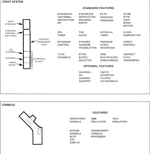
470V17 SYSTEM
STANDARD FEATURES
SYSTEM/370 SYSTEM/370 BYTE- 32,768 UNIVERSAL INSTRUCTION ORIENTED BYTE INSTRUCTION ENHANCE· OPERANDS HIGH MAIN
SET MENTS SPEED
STORAGE
BUFFER
STORAGE
CPU TOD INTERVAL CLOCK
CONTROL
UNIT (SCU) TIMER CLOCK TIMER COMPARATOR
CENTRAL
A:-PROCESSOR EXTENDED DYNAMIC PROGRAM DIRECT
(CPU) CONTROL ADDRESS EVENT CONTROL
TRANSLATION RECORDING LSI
CHANNEL-....
12 I/O BYTE/ 2048 INDIRECT
CHANNEL-.... CHANNELS CHANNELS BLOCK/ MULTIPLEXER DATA SELECTOR SUBCHANNELS ADDRESSING CABLE (C-UNITI
ENTRV--A..
OPTIONAL FEATURES
CHANNEL- 2-BYTE
TO- INTERFACE
CHANNEL 4 EXTRA ADAPTER I/O CHANNELS
CONSOLE·
FEATURES
OPERATOR'S 3066 3215 CONSOLE EMULATION EMULATION
. SYSTEM INDEPENDENT CONSOLE CONSOLE WITH PROCESSOR CRT
DISPLAY
POWER DISTRIBUTION UNIT
FEATURES
D
EMERGENCY 415 Hz and [image:7.613.42.546.63.579.2]470V/7 MACHINE REFERENCE MANUAL
SYSTEM OVERVIEW
CENTRAL PROCESSOR (CPU)
The Amdahl 470V17 central processor (CPU) com-prises three units: the Instruction Unit, the Execu-tion Unit, and the Storage Unit (see figure 1). It includes these standard features:
STANDARD ARCHITECTURE. The Amdahl 470
VI7 follows standard System/370 architecture as specified in the IBM Systeml370 Principles ofOp-eration. The standard, full System/370 Universal
Instruction Set with extended-precision floating-point operations and System/370 instruction en-hancements is implemented on the Amdahl 470 V 17. Direct control is also implemented.
INSTRUCTION PIPELINE. The 470V17 Instruc-tion Pipeline allows the CPU to process several instructions simultaneously and reduces the cycles lost in a program branch to three.
HIGH-SPEED BUFFER. The High-Speed Buffer (HSB) is a cache memory designed to maximize system throughput. It provides fast access to fre-quently used data.
TRANSLATION LOOKASIDE BUFFER. The 512-entry Translation Lookaside Buffer (TLB) provides high-speed storage of frequently used virtual ad-dress translations. A segment table origin stack, which associates a specific CPU state with each TLB entry, further enhances virtual address trans-lation in the 470V 17.
TIMING FACILITIES. Standard System/370 timing facilities are provided. These include an interval timer, a time-of-day clock with 52 bit resolution, a 52-bit clock comparator, and a CPU timer.
SYSTEM CONSOLE
The 470V17 system console not only acts as an op-erator's console but serves as an independent main-tenance tool as well. It includes an operator's con-trol panel, a keyboard and CRT display, and an independent console processor.
SYSTEM OVERVIEW
MAIN STORAGE
Main storage is available in configurations of 4, 6, 8, 12, and 16 megabytes. Main storage is interleaved 16 ways on a double word basis. Error checking and correction (ECC) corrects single bit errors and detects double-bit errors on a doubleword basis. Failing portions of main store can be configured out of the system in two-megabyte blocks. Access to main storage is controlled by the Storage Con-trol Unit.
CHANNELS (C-UNIT)
The Amdahl 470V17 system has physically inboard channels, with 12 standard and 4 more channels available as an option. These may all be installed in any combination of selector, byte-multiplexer, or block-multiplexer channels. The channels are im-plemented by the Channel Unit, and except for possible storage-access conflicts, they operate in-dependently of the CPU. A total of 2048 subchan-nels may be assigned to the multiplexer chansubchan-nels in multiples of 32, up to 256.
POWER DISTRIBUTION UNIT
SYSTEM OVERVIEW
OPTIONAL FEATURES
CHANNEL-TO-CHANNEL ADAPTER. This option provides the synchronization necessary to intercon-nect two channels. It may be attached to a selector or a block-multiplexer channel and uses one control unit position on each channel. When interconnect-ing an Amdahl 470V/7 system with another sys-tem, either may be equipped with the channel-to-channel adapter.
TWO-BYTE INTERFACE. The standard channel interface provides a one-byte-wide data path
be-470V/7 MACHINE REFERENCE MANUAL
tween controllers and a channel. A two-byte inter-face effectively doubles the bandwidth for COritrol units that support this feature. The two-byte inter-face option is available on selector and multiplex-er channels.
470V!7 MACHINE REFERENCE MANUAL
INSTRUCTION UNIT
I-UNIT FUNCTIONS
The Instruction Unit (I-Unit) executes the instruc-tion stream, updates the CPU timer, and processes interrupts and machine checks. It also contains the general-purpose registers, floating-point registers, control registers, and PSW.
To execute instructions, the I-Unit uses the facili-ties of the other 470 components. The E-Unit per-forms arithmetic and logical operations; the C-Unit performs input and output operations; the S-Unit writes and retrieves data and instructions in main storage. Because it controls the flow of in-structions, the I-Unit directly or indirectly initiates the operations of all other units.
PROCESS CONTROL
INSTRUCTION SELECT
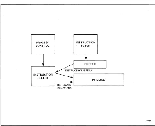
FIGURE 2 I-UNIT ORGANIZATION
HARDWARE FUNCTIONS
INSTRUCTION UNIT
I-UNIT ORGANIZATION
The I-Unit functions (figure 2) can be summarized into the following major categories:
• Interrupt priority resolution and operation selection
• Instruction fetch and instruction buffer reg-ister control
• Instruction path selection In the case of
branches or interrupts
• Pipeline processing of the instruction stream
INSTRUCTION FETCH
PIPELINE
[image:10.612.62.567.303.715.2]INSTRUCTION UNIT
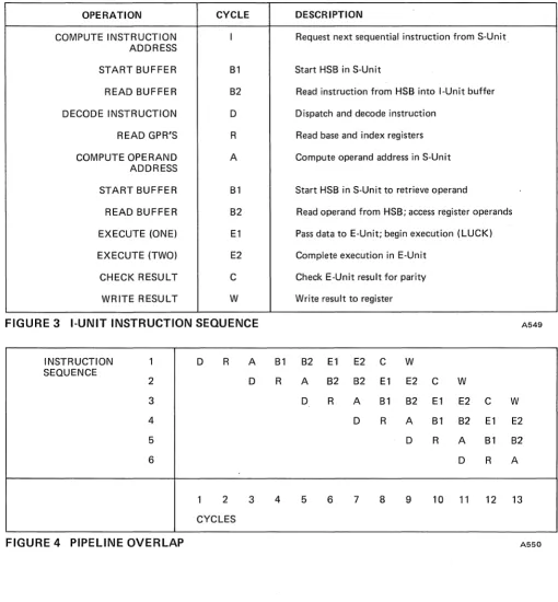
The pipeline is a major factor in the high perform-ance of the Amdahl 470VI7. It decodes instruc-tions, reads general purpose registers (GPRs), com-putes operand addresses, requests operands, initiates operand modification, and checks and writes re-sults. Modifying operands requires the facilities of the E-Unit. Fetching and storing operands requires the facilities of the S-Unit. By overlapping all these described functions, a large performance enhance-ment is achieved over non-pipe1ined processors. The purpose of the pip/eline is to allowarchitec-tural instructions to proceed at the maximum speed of the execution hardware, rather than hav-ing to wait for auxiliary functions to be completed. Thus, the pipeline typically begins executing each instruction before it has finished executing the previous one. Because of this, the 470V17 pipeline will often be processing several instructions simul-taneously. Figures 3 and 4 illustrate the concept of pipeline overlap.
One of the problems inherent in pipeline design re-lates to the handling of branch instructions, or those conditions where prefetching and overlap of instructions is impossible because of multiple pos-sible execution paths. Rather than resort to an ex-pensive and massive duplication of hardware to follow multiple branch paths, Amdahl invented and implemented a unique, fast branch-resolution algorithm. The hardware to accomplish this func-tion is primarily in the E-Unit, which tells the 1-Unit the branch condition codes before the subject instruction has even completed execution. Thus the I-Unit is able to pick the correct branch path immediately, and the correct instruction stream proceeds down the pipeline with only a small
470V/7 MACHINE REFERENCE MANUAL
"hole" (lost time) of three cycles. Even this rela-tively small degradation can be eliminated if the branch is not taken. Thus the 470V17 branching algorithms complement an optimal pipeline . or-ganization to produce significant performance in the execution of the machine object-instructions.
HARDWARE INSTRUCTION
RETRY
.
.
To enhance total system availability and reliability, almost all 470V 17 functions are retriable. This is accomplished within the total system design of the 470V /7 Instruction Unit by delaying any updates to architectural registers until the last cycle of in-struction execution. Thus, the pipeline concept is extended to include enhancements to machine in-tegrity, so that any errors that occur before regis-ters are updated simply cause re-execution of the instruction. This method of instruction retry mini-mizes the hardware involved in error detection and therefore increases the effectiveness of the overall 470V/7 checking and correction mechanisms, while providing maximum recovery capability.
INTERRUPT HANDLING
470V!7 MACHINE REFERENCE MANUAL INSTRUCTION UNIT
OPERATION CYCLE DESCRIPTION
COMPUTE INSTRUCTION I Request next sequential instruction from S-Unit
ADDRESS
START BUFFER B1 Start HSB in S-Unit
READ BUFFER B2 Read instruction from HSB into I-Unit buffer
DECODE INSTRUCTION D Dispatch and decode instruction
READ GPR'S R Read base and index registers
COMPUTE OPERAND A Compute operand address in S-Unit
ADDRESS
START BUFFER B1 Start HSB in S-Unit to retrieve operand
READ BUFFER B2 Read operand from HSB; access register operands
EXECUTE (ONE) E1 Pass data to E-Unit; begin execution (LUCK)
EXECUTE (TWO) E2 Complete execution in E-Unit
CHECK RESULT C Check E-Unit result for parity
WRITE RESULT W Write result to register
FIGURE 3 I-UNIT INSTRUCTION SEQUENCE A549
INSTRUCTION 1 D R A B1 B2 E1 E2 C W
SEQUENCE
2 D R A B2 B2 E1 E2 C W
3 D R A B1 B2 E1 E2 C W
4 D R A B1 B2 E1 E2
5 D R A B1 B2
6 D R A
1 2 3 4 5 6 7 8 9 10 11 12 13
CYCLES
[image:12.613.63.573.55.604.2]EXECUTION UNIT
EXECUTION UNIT
E-UN IT FUNCTIONS
The Execution Unit (E-Unit) performs all logical and arithmetic operations. It also sets condition codes and checks for errors.
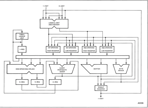
E-UN IT ORGAN IZATION
The E-Unit is divided into six subunits: Logical Unit and Checker, Adder, High-Speed Multiplier, Shifter, Byte Mover, and Table Lookup Unit. .
LOGICAL UNIT AND CHECKER. The Logical Unit and Checker (LUCK) performs these functions:
• Logical operations: AND, OR, Exclusive-OR.
• Compares operands.
• Sets early condition codes: returns the condi-tion code after one cycle for many operacondi-tions.
• Checks parity of input, predicts parity of re-sult.
• Checks decimal input for valid digits and sign.
• Counts leading zeros for normalization opera-tions.
• Moves input data to E-Unit internal registers.
ADDER. The adder performs standard binary and decimal addition. It can add two single-word oper-ands per cycle.
HIGH-SPEED MULTIPLIER. The multiplier multi-plies an 8-bit multiplier with a 3 2-bit multiplicand and produces a 40-bit result every cycle.
470V!7 MACHINE REFERENCE MANUAL
. SHIFTER. The shifter performs shift operations. A maximum of 68 bits can be input to the shifter. The operand can be shifted left or right, from 0 to 63 bit positions.
BYTE MOVER. The byte mover manipulates single-byte fields for such operations as EDIT, EDIT AND MARK, TRANSLATE, and TRANSLATE . AND TEST.
TABLE LOOKUP UNIT. The Table Lookup Unit finds reciprocals of operands. These are used in di-vision operations.
INSTRUCTION EXECUTION
The I-Unit presents instructions to the E-Unit and also provides intermediate scratch space for complex operations. The E-Unit accepts instructions at a maximum rate of one every two cycles. Data comes to the E-Unit from either the I-Unit or the S-Unit.
The E-Unit begins each instruction in the LUCK. The LUCK performs the appropriate functions, and, if possible, sets an early condition code in the first cycle of E-Unit execution. When it is finished, the LUCK moves the input data into four internal registers. The operands are now available to the ad-der, multiplier, shifter, or byte mover.
470V!7 MACHINE REFERENCE MANUAL
MUL TIPLICATION
The multiplier multiplies a full-word first operand by one byte of the second operand and repeats this operation until each byte of the second operand has been used. Each iteration requires one cycle. At the end of the operation, the final result is placed into the result register. Refer to figure 5.
DIVISION
The 4 70V 17 performs division by multiplying the
dividend by the reciprocal of the divisor. The Table Lookup Unit finds the inverse of the divisor and places it into the I-register. The multiplier then uses· the inverse as an operand,
I-U~.IT S-UNIT
I
+
+
LOGICAL UNIT AND CHECKER
+
II
TABLEI
LOOKUP UNIT
I T
+
+ +
$
1ST OPERANDI
HIGH REGISTERlIST OPERAND LOW REGISTER
+
+
I
EXECUTION UN IT
CONDITION CODES
The LUCK can set an early condition code for most operations that set a condition code. However, some operations are so complex that the condition code cannot be set until the operation is complete. In this case, the I-Unit branch handling waits for the E-Unit to finish. For some other operations, the E-Unit can set the condition code in the middle of the operation. In this case, the E-Unit signals the 1-Unit when the condition code will be set.
ERROR CHECKING
All execution results are checked in the 470V/7. This checking includes parity checks for most op-erations, and a more comprehensive residue arith-metic check for multiplication and division.
T T
+ +
+ +
I
2ND OPERANDI
HIGH REGISTERI
2ND OPERAND
I
LOW REGISTER+
+
I
I t
---.Jl
~
-.~
.-M
\
/
~
HIGH·SPEED MULTIPLIER PROPAGATE CARRY SHIFTER
MOVER ADDER
~
!
+
I
C-REGI I
S-REG A-REGI
~
l
II
RESULTREGISTER
1
+
I-UNITA526
[image:14.613.67.569.354.720.2]CHANNEL UNIT
CHANNEL UNIT
C-UN IT FUNCTIONS
The Channel Unit (C-Unit) implements the 470V /7 inboard channels. Except for occasional memory-access conflicts, these channels operate independ-ently of the CPU. The channels may be configured in any combination of selector, byte-multiplexer, or block-multiplexer channels.
The C-Unit (figure 6) is implemented in large-scale-integration (LSI) technology. Associated with the C-Unit is the channel frame, which is implemented in non-LSI (third generation) technology. The chan-nel frame contains the Remote Interface Logic (RIL), Channel Buffer Store (CBS), Subchannel Buffer Store (SBS), and other hardware used by the C-Unit. The C-Unitperforms the 110 commands defined in the Systeml370 Principles of Operation
and controls data movement to and from the S-Unit, data movement over the standard 110 inter-face, and communication with the I-Unit and S-Unit. The channel frame translates LSi signals to standard interface signals, drives and receives inter-face signals, and buffers I/O data.
C-UNIT ORGANIZATION
The C-Unit and channel frame together implement the channels. These channels share the same control logic. The Shifting Channel State (SCS) coordinates activities among the channels. Other parts of the C-Unit are the Controller Interface Control Logic (CICL), the Data Access Control Logic (DACL), and the Operations Control Logic (OCL).
SHIFTING CHANNEL STATE (SCS). The SCS maintains the current state of each channel. It is used by the OCL, DACL, and CICL. The status in-formation for each channel rotates through the SCS by one step per cycle. Thus the OCL, DACL, and CICL can examine a different channel every cycle. The OCL, DACL, and CICL update the in-formation in the SCS when appropriate; the SCS then forwards the new information.
470V!7 MACHINE REFERENCE MANUAL
CONTROLLER INTERFACE CONTROL LOGIC (CICL). The CICL moves data between the channel buffer store and the RIL and controls channel frame operations. The CICL has two ports into the SCS and two ports into the channel buffer store (CBS). Every two cycles, the CICL services two channels.
DATA ACCESS CONTROL LOGIC (DACL). The DACL moves and controls data between the S-Unit and C-Unit buffers. It examines each channel in the SCS once every 16 cycles. For an input operation, the data goes from the CBS to the S-Unit.· The DACL is pipelined to overlap operations: while one section may be fetching data from the S-Unit, an-other may be posting results to the SCS. The DACL assigns each channel a dynamic priority based on the amount of data in its buffer. A priority change can occur while a fetch or store is in progress. The DACL attempts to select the highest-priority chan-nel in the SCS to service.
OPERATIONS CONTROL LOGIC (OCL). The OCL sets up channel transfer sequences and coordinates channel program execution within the C-Unit. It sets up counts, flags, and data transfer addresses in the C-Unit buffers (normally the CBS), and it trans-lates CCWs into CICL and DACL actions. The OCL obtains its control information directly from the 1-Unit and S-1-Unit over an interface shared with the DACL.
470V!7 MACHINE REFERENCE MANUAL
CHANNEL OPERATION
The data path through the channel is shown in fig-ure 6. The OCL interprets the channel program and indicates in the SCS the desired action for the ap-propriate channel. If the DACL sees an output re-quest in the SCS, it fetches the data from the S-Unit and stores it in the CBS. The CICL then moves the data from the CBS to the RIL, which moves it to the external device. If the CICL sees an input re-quest in the SCS, it fetches the data from the RIL and moves it to the CBS. The DACL then moves the data to the S-Unit.
MULTIPLEXING
The OCL coordinates subchannel activity for byte and block multiplexing. It stores inactive sub chan-nel information in the Sub chanchan-nel Buffer Store (SBS) and maintains subchannel status.
c:J
tl--____ ...
~I
OCL
CBS
CHANNEL UNIT
INDIRECT DATA ADDRESSING
Channel Indirect Data Addressing (IDA) as de-scribed in the Systeml370 Principles of Operation
is fully implemented in the Amdahl 4 70V /7 sys-tem. IDA requires a control program to perform virtual-to-real address translations before a data-transfer command is executed by the channel.
CHANNEL TYPES
Any 4 70V /7 channel can be configured as a block multiplexer, byte multiplexer, or selector. Selector channels transfer only in burst mode and may ad-dress up to 256 110 devices one at a time. Multi-plexer channels execute several channel programs concurrently. Each channel program requires its own subchannel; therefore, the number of concur-rent channel programs cannot exceed the number of allocated subchannels. For an explanation of sub channel assignment, see page 28.
LSI C-UNIT
DACL CICL
STANDARD I/O INTERFACE
t
RIL
S-UNIT ~--...
- - + - -...
-+--~I-UNIT . . - - - -...
A527
[image:16.613.70.572.386.719.2]CHANNEL UNIT
CHANNEL BANDWIDTH
When allocating devices to channels, the channel bandwidth must be considered. Specific character-istics of certain high-speed devices can affect chan-nel bandwidths; therefore, chanchan-nel assignments for high-speed devices should be confirmed with an Amdahl representative.
SELECTOR. The maximum data rate on a selector channel is approximately two megabytes per second. An optional 2-byte interface doubles this rate.
BLOCK MULTIPLEXER. The maximum data rate on a standard, single-byte, block-multiplexer
chan-470V!7 MACHINE REFERENCE MANUAL
nel is approximately two megabytes per second. An optional 2-byte interface doubles this rate.
BYTE MULTIPLEXER. The maximum data rate for a byte-multiplexer channel in byte-multiplex mode is approximately 110 kilobytes per second.
470V/7 MACHINE REFERENCE MANUAL
STORAGE UNIT
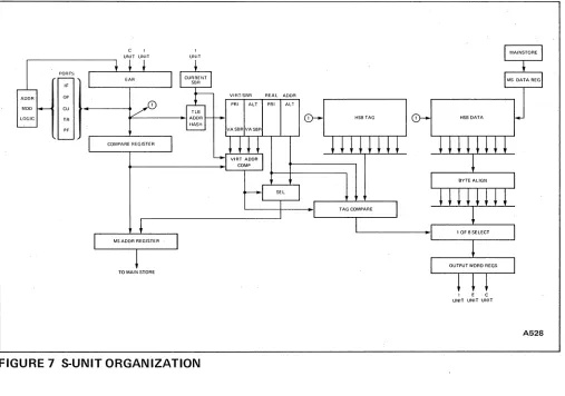
S-UN IT FUNCTIONS
The Storage Unit (S-Unit) performs all main storage requests from the I-Unit, E-Unit, and C-Unit. It also performs Dynamic Address Translation (DAT). See figure 7.
S-UNIT ORGANIZATION
Three features increase the speed of the S-Unit: the
Hi~h-Speed Buffer (HSB), the Translation Look-aside Buffer (TLB), and the Segment Table Origin (STO) stack.
HIGH SPEED BUFFER. The HSB contains fre-quently used lines of memory. Because an HSB ac-cess is much faster than a main storage acac-cess, the S-Unit saves time by using the HSB to retrieve and write data.
TRANSLATION LOOKASIDE BUFFER. TheTLB is a 512-entry table of frequently used virtual ad-dresses with their real address translations. By using the TLB, the S-Unit can avoid translating most ad-dresses.
SEGMENT TABLE ORIGIN (STO) STACK. A 128-entry STO stack saves the data from co.ntrol regis-ters 0 and 1 that define the current segment table. Each TLB entry is associated with an STO stack entry. Instead of purging the TLB· whenever con-trol registers 0 and 1 change, the S-Unit checks the STO ID of TLB entries to make sure they are valid with the current control register values. Up to 128 different virtual-address spaces can have currently valid identification information in the STO stack. Thus, at the same time, up to 128 different virtual-address spaces can have active translation informa-tion in the TLB.
STORAGE UNIT
S-UN IT OPE RATION
When the S-Unit receives a virtual address, it starts the HSB and TLB simultaneously. While it uses the low-order (real) bits of the virtual address to create a pointer into the HSB, it uses the high-order virtual address bits to translate to a real address. It usually finds the real address in the TLB by the time it needs the high-order real address bits in the HSB. If the virtual address is not in the TLB, the S-Unit performs a complete translation and puts the ad-dress into the TLB. After using the real adad-dress to decide which bytes in the HSB were requested, the S-Unit forwards these bytes to the I-Unit, E-Unit, or C-Unit. If the requested bytes are not in the HSB, the S-Unit retrieves them from main storage, loads the 32-byte storage line containing the re-quested bytes into the HSB, and concurrently by-passes the data to the requesting unit. Refer to fig-ure 7.
HIGH-SPEED BUFFER (HSB)
HIGH-SPEED BUFFER ORGANIZATION
The 470V/7 HSB is a 32,768-byte (32K) set-associ-ative memory. It is divided into eight parts. Each part contains128 32-byte lines.
TWO-KILOBYTE PAGING
STORAGE UNIT
C I
PORTS
~~
]---+
TR ~---I
PF
MOD
LOGIC
TO MAIN STORE
FIGURE 7 S-UNIT ORGANIZATION
HIGH-SPEED BUFFER TAG
Each line in the HSB has a tag associated with it. This tag contains three fields that identify and pro-tect the data: tag-identifier, key, and status. Refer to figure 8. The tag-identifier field contains the real address. The key field contains five protection-key bits, a parity bit, and a check bit. The status field specifies whether the line is valid and unmodified, valid and modified, or invalid. It also specifies the type of modification: an ECC correction or a store made under program control. The status field can be recovered from a single-bit error.
TAG IDENTIFIER KEY STATUS
(REAL ADDRESS BITS) 01234 PC 0123
470V!7 MACHINE REFERENCE MANUAL
HSB TAG
l E e UNIT UNIT UNIT
FINDING A LINE IN THE HSB
A528
When the S-Unit references the HSB, it first forms a pointer into the buffer using bits 20-26 of the requested address. This pointer defines eight corres-ponding lines (refer to figure 9).
The S-Unit must decide which of these eight lines contains the requested bytes. To do this, it com-pares the tag-identifier fields of all eight tags with the corresponding real address. (These real address bits are determined by dynamic address translation (DAT».
[image:19.612.42.549.56.412.2] [image:19.612.43.284.601.696.2]470V!7 MACHINE REFERENCE MANUAL
TAG
TLB
I
A B C D E F G ALADDRRE
8-20 PR I ALT
,
,
TAG COMPARE (16 WIDE)
FIGURE 9 HIGH-SPEED BUFFER OPERATION
FETCHING A LINE FROM THE HSB
If the S-Unit is fetching a line from the HSB, it finds the eight possible lines and performs a tag compare. If one of the tags matches the real address bits, the resulting data selection forwards the de-sired bytes to the word registers, where they are available to the I-Unit, E-Unit, or C-Unit. If no tag matches the real address bits, the requested bytes are not in the buffer. In this case, the S-Unit moves the line into the HSB from Main Storage.
MOVING A LINE INTO THE HSB
To move a line into the HSB, the S-Unit fetches from main storage the 32-byte line containing the requested byte and creates a tag for the line, using the real address bits.
H
STORAGE UNIT
VIRTUAL ADDRESS
8-20 20-26 27-31
DATA
A B C D E F G H ~
BYTE ALIGN I
I
,
I 1 OF 8 SELECT
WORD REGISTER
It
E I C UNIT UNIT UNIT
A530
Because each storage line maps into eight specific HSB locations, the S-Unit must decide which of the lines already at the given locations to replace with the new lines. If a line is invalid, it is replaced immediately. If no line is invalid, the S-Unit re-places the least recently used line. If the line to be replaced is modified, it is written to main storage as the new line replaces it. (This write to main stor-age occurs in the background with no additional delay.)
STORING DATA IN THE HSB
[image:20.613.68.576.61.433.2]STORAGE UNIT
To store data in the HSB, the S-Unit finds the ap-propriate line, updates the requested bytes, and sets the status field of the tag to show that the line is modified.
HSB RECONFIGURATION
If a buffer error occurs, the HSB is reconfigured by disabling the part in error. The rest of the HSB re-mains available to the system.
DYNAMIC ADDRESS
TRANSLATION (DAT)
The 470V/7 can perform dynamic address transla-tion (DA T) when in EC mode. Virtual addressing in the 4 70V /7 operates as defined in the System/ 370 Principles of Operation.
When the S-Unit performs an address translation using the segment and page tables, it saves the result in the Translation Lookaside Buffer (TLB).
STO STACK AND TLB ORGANIZATION
The segment table origin stack (STO) has 120 loca-tions. It is addressed by the current segment table origin. Each STO stack entry records pertinent data from a recent value of control registers 0 and 1.
One other bit, called the flipper bit, distinguishes old STO stack entries from new ones. The STO ad-dress and the flipper bit together constitute an STO ID.
470V/7 MACHINE REFERENCE MANUAL
The translation lookaside buffer (TLB) is divided into a primary half and an alternate half. Each half has 256 locations. The TLB address is a mapping of the current STO ID and the virtual address. The primary half and the alternate half are each ad-dressed with a different mapping function. By mak-ing TLB address assignment more random, the map-ping function reduces TLB address conflicts.
STO STACK ENTRIES
Whenever the value of control registers 0 and 1 changes, the S-Unit examines the STO stack entry addressed by the current segment table origin. If this location is empty, the S-Unit creates a new en-try in the table. If there is already an enen-try, the S-unit compares it to the current value of control registers 0 and 1. If the entry and registers match, the entry is still valid. If they do not match, the S-Unit creates a new entry, writes it into the stack, and purges all TLB entries associated with the old STO ID.
SAVING A TRANSLATION
470V/7 MACHINE REFERENCE MANUAL
RETRIEVING A TRANSLATION
When· the S-Unit retrieves an address translation from the TLB, it first finds the two entries, primary and alternate, to which the presented virtual address maps. Then it compares bits 8-20 of the virtual address to these two entries to find the one that matches. Simultaneously, the S-Unit comapres the STO ID of both entries to the currently valid STO ID. If the presented virtual address and the current STO ID match one of the TLB entries, the associ-ated real frame address is forwarded as the real ad-dress. If not, a full translation is performed and the new virtual/real pair is saved in the TLB.
PURGE TLB
To enhance performance, the TLB has two sets of valid bits. When the PURGE TLB instruction is
exe-cuted, the S-Unit immediately switches to the other set of valid bits, which are all marked invalid. The
STORAGE UNIT
S-Unit then resets the older set of valid bits in par-allel with subsequent buffer accesses. Because PURGE TLB is issued relatively infrequently, the alternate set of valid bits will usually be reset by the time they are needed again, and the instruction will normally require only a few cycles.
ERROR CHECKING
AND CORRECTION
SYSTEM CONSOLE
SYSTEM CONSOLE
CONSOLE FUNCTIONS
The 470V17 System Console provides communica-tion with the 470, usage metering, diagnostic infor-mation on the hardware, and intermediate storage for machine-check logouts.
On the 470, most console input is entered on the keyboard rather than on toggle or rotary switches, and most console output appears as a formatted CRT display rather than a panel-light display.
COMMUNICATION. The console provides all stan-dard communication between the 470V17 proces-sor and the operator. It emulates a 3066 or 3215 operator's console, performs functions such as IPL, reset, and clear, and displays diagnostic messages and the contents of registers, latches, and storage.
MACHINE-CHECK LOGOUT STORAGE. The 470 V /7 system console stores machine-check logout information on its attached disk. This makes it pos-sible to save over a hundred scan pages at the time of a machine failure and to later display these pages at the console.
470V!7 MACHINE REFERENCE MANUAL
DIAGNOSTIC INFORMATION. The 470V17 con-sole provides formatted displays of appr.oximately 17,000 latches within the 470 system. These dis-plays are called "scan pages" j each scan page gives
the current status of one area or function of the machine. The console also gives a continuous machine-status display at the top of the CRT screen. This display summarizes the current state of the 470.
470V!7 MACHINE REFERENCE MANUAL
CONSOLE COMPONENTS
The 470V/7 system console includes a CRT display screen, a keyboard, a standard channel interface, a computer-to-console interface, an independent pro-cessor, and a modem.
The standard channel interface is used when the 4 70V /7 is using the console to emulate a 3066 or a 3215. The computer-to-console interface is used when the console is reading scan information or is~
suing hardware commands to the 470.
The console processor is a minicomputer that allows the console to operate independently of the rest of the 470. The console can interrogate and diagnose the 470, whether it is running or stopped, even if the 470 is not operational. The console processor also performs 470 hardware functions such as Dis-play Register or Alter Register. A disk and diskette are attached to the console processor.
The modem allows remote access to the 4 70V /7. Through the modem, the Amdahl central mainten-ance diagnostic facility, AMDAC, can diagnose problems from Amdahl headquarters.
SYSTEM CONSOLE
CONSOLE OPERATION
The 4 70V /7 console operates in one of two modes: device support mode and hardware command mode.
DEVICE-SUPPORT MODE. In device-support mode, the console simulates the device support mode of an IBM 3066 or 3215 operator's console. This allows the operator to communicate with the system control program. In this mode, the console acts as a control unit and may be connected to
either a selector o~ block-multiplexer channel.
INSTRUCTION SET DIFFERENCES 470V!7 MACHINEREFERENCEMANUAL
INSTRUCTION SET DIFFERENCES
Two instructions have important model-dependent results on the Amdahl 470V17. They are: STORE CPU ID (STIDP) and STORE CHANNEL ID (STIDC).
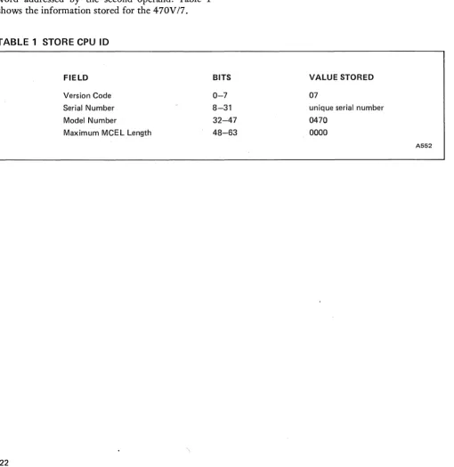
STORE CPU ID
snDP stores model-dependent data at the double word addressed by the second operand. Table 1 shows the information stored for the 470V17.
TABLE 1 STORE CPU ID
FIELD
Version Code
Serial Number Model Number
Maximum MCEL Length
BITS
0-7
8-31
STORE
CHANNEL 10
STJDC stores channel-dependent data at decimal location 168. Because the 470V17 channel model is implicit in the CPU model, zeros are stored in the channel model-number field. The remaining fields, channel type and JOEL length, follow stan-dard conventions.
VALUE STORED
07
unique serial number
32-47 0470
48-63 0000
[image:25.613.55.565.231.756.2]470V!7 MACHINE REFERENCE MANUAL MACHINE CHECK CONDITIONS
MACHINE·CHECK CONDITIONS
The Amdahl 4 70V /7 system is continuously check-ing for valid data, instructions, arithmetic results, and legal control sequences. When an error is dis-covered, it can often be corrected without serious impact on machine performance.
Malfunctions causing machine-check interrupts (see figure 10) are grouped into two categories: repres-sible and exigent. These are defined in the System! 370 Principles of Operation.
REPRESSIBLE CONDITIONS
Repressible conditions comprise system recovery conditions, timer damage conditions, time-of-day clock damage, external damage, and degradation of
the segment table origin stack. These conditions do not terminate the current instruction or cause loss of interrupts.
A machine-check interrupt for a repressible condi-tion occurs after an instruccondi-tion, including any as-sociated SVC interrupt or program interrupt, has completed. (This is the same point at which an I/O interrupt occurs.)
EXIGENT CONDITIONS
Exigent conditions comprise system damage condi-tions, multi-bit storage errors, protection-key parity errors, unretrievable internal data-transfer errors, move-out parity errors, and instruction processing
SIP'S'T'CIEI
,
D,
I I IS IS K IW 1M ' P I I I FIR I 'F IG'c'
Dp,R p,D,D, G B D E C E PSMAAC P R R
0 6 7 8 14 20 24 272829 31
::
4647:~:
63BIT FUNCTION BIT FUNCTION
SO System damage KE Storage Key error uncorrected
PO Processor damage WP PSW EMWP valid
SR System recovery MS PSW masks and key valid
TO Timer damage PM Program masks and CC valid
CD Timing facilities damage IA Instruction address valid
ED External damage FA Failing storage address valid
DG Degradation RC Region code valid
B Backed-up FP Floating point registers valid
0 Delayed GR General purpose registers valid
SE Storage error uncorrected CR Control registers valid
SC Storage error corrected TR CPU timer valid
CC Clock comparator valid
A532
[image:26.613.59.565.347.708.2]MACHINE CHECK CONDITIONS
damage conditions (if retry is unsuccessful or im-possible).
A machine-check interrupt for an exigent condition immediately inhibits any updating of the machine state, including storage and registers, without wait-ing for an instruction to end. It points the instruc-tion counter to the instrucinstruc-tion farthest along in the pipeline, although any of the instructions in the pipeline may have caused the error.
SYSTEM RECOVERY
CONDITIONS
The 470V /7 system has two facilities for error cor-recti on: Hardware Instruction Retry (HIR) and Error Checking and Correction (ECC). Any cor-rected error causes a system recovery condition.
HARDWARE INSTRUCTION RETRY. When an error is detected in the execution of an instruction, the HIR circuitry can usually retry the instruction.
If the retry is successful, the machine check is re-pressible. If the retry is unsuccessful, the machine check is exigent.
470V!7 MACHINE REFERENCE MANUAL
ERROR CHECKING AND CORRECTION. Each 8-byte section of main storage has an ECC field as-sociated with it. This field contains sufficient in-formation to correct any single-bit error within the 8 bytes.
I/O ERRORS
A malfunction detected by the S-Unit during an 110 operation causes an external-damage machine-check condition. If the error occurs while the chan-nel is fetching a CCW or data, the malfunction is reported in the channel status word (CSW). If the error occurs while the channel is storing data, and the S-Unit detects the error after status has been returned to the C-Unit, the CSW does not report the error. When the channel detects bad parity dur-ing an input operation, good parity is forced to the S-Unit and a channel data check is reported in the CSW.
When the C-Unit detects an external I/O equip-ment malfunction, it reports the error in a CSW as an 1/0 interrupt. The error is not handled as a ma~
470V!7 MACHINE REFERENCE MANUAL
MACHINE-CHECK LOGOUTS
FIXED LOGOUT AREA
The 104-byte area starting at location 248 is re-served for machine-check logouts. The Amdahl 470 V /7 uses only the first 12 bytes of this area. The failing storage address (FSA) occupies the word starting at location 248; the region code occupies the three words starting at location 252. The rest of the area, locations 264-351, is reserved.
FAILING STORAGE ADDRESS (FSA). The FSA indicates the byte or block in which the error oc-curred. For a correctable storage error, bits 1-3 of the FSA contain the failing bit address; bits 8-31 contain the failing byte address. For an uncorrect-able storage error, bits 8-28 of the FSA point to the failing 8-byte ECC block. For an uncorrectable protection-key error, bits 8-31 of the FSA may point anywhere within the 2048-byte protection block. In the case of multiple errors, the FSA may point to anyone of the failing locations. In some cases, an FSA cannot be stored. When this occurs, the FSA valid bit in the machine-check interrupt code is set to zero.
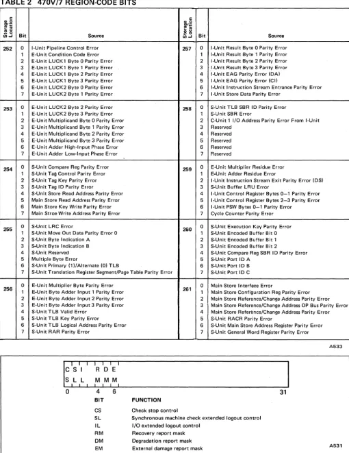
REGION CODE. The region code specifies which part of the machine detected the error. Table 2 de-fines the region code bits.
MACHINE CHECK EXTENDED
LOGOUT
The 470V/7 performs a machine-check extended logout (MCEL) when a machine check occurs and the mask bits of control register 14 are set to allow
MACHINE-CHECK LOGOUTS
the logout. The logout on a 470V/7 includes a set of scan pages that record the state of approximate-ly 17,000 latches in the system. These are the same scan pages that can be displayed at the console in hardware command mode. The console processor its memory or attached disk.
While the console processor performs the MCEL, the CPU suspends processing. When the logout is complete, the console restarts the CPU, which can then perform its own machine-check handling rou-tines.
Machine-check handling software can access the console logout in two ways: through the channel or through the computer-to-console interface (CCI). Both methods will transfer the logout from the console to main storage.
CONTROL REGISTERS 14 AND 15
Because MCEL data is saved in the console, control register 15, which normally contains the MCEL ad-dress, is not implemented on the 4 70V /7 and stores as all zeros.
The significant bits of control register 14 appear in figure 11. These bits operate as defined in the Sys-teml370 Principles of Operation. Bit 4, recovery
MACHINE-CHECK LOGOUTS 470V!7 MACHINE REFERENCE MANUAL
TABLE 2 470V!7 REGION-CODE BITS
c c
.. 0 .. 0
"'.-
"'.-~;
....
~..
o u o u
.. 0
Bit Source .. 0 Bit Source
111-1 111....1
252 0 I-Unit Pipeline Control Error 257 0 I·Unit Result Byte 0 Parity Error 1 E·Unit Condition Code Error 1 I-Unit Result Byte 1 Parity Error 2 E-Unit LUCK 1 Byte 0 Parity Error 2 I-Unit Result Byte 2 Parity Error 3 E-Unit LUCK 1 Byte 1 Parity Error 3 I-Unit Result Byte 3 Parity Error
4 E-Unit LUCK1 Byte 2 Parity Error 4 I·Unit EAG Parity Error (DA) 5 E·Unit LUCK 1 Byte 3 Parity Error 5 I-Unit EAG Parity Error (Cil
6 E-Unit LUCK2 Byte 0 Parity Error 6 I-Unit Instruction Stream Entrance Parity Error
7 E-Unit LUCK2 Byte 1 Parity Error 7 I·Unit Store Data Parity Error
253 0 E-Unit LUCK2 Byte 2 Parity Error 258 0 S·Unit TLB SBR ID Parity Error 1 E-Unit LUCK2 Byte 3 Parity Error 1 S-Unit SBA Error
2 E-Unit Multiplicand Byte 0 Parity Error 2 C-Unit 1 I/O Address Parity Error From I·Unit 3 E-Unit Multiplicand Byte 1 Parity Error 3 Reserved
4 E-Unit Multiplicand Byte 2 Parity Error 4 Reserved
5 E·Unit Multiplicand Byte 3 Parity Error 5 Reserved
6 E-Unit Adder High·lnput Phase Error 6 Reserved
7 E-Unit Adder Low·lnput Phase Error 7 Reserved
254 0 S-Unit Compare Reg Parity Error 259 0 E-Unit Multiplier Residue Error 1 S-Unit Tag Control Parity Error 1 E-Unit Adder Residue Error
2 S-Unit Tag Key Parity Error 2 I-Unit Instruction Stream Exit Parity Error (DS) 3 S-Unit Tag ID Parity Error 3 S·Unit Buffer LRU Error
4 S-Unit Store Read Address Parity Error 4 I·Unit Control Register Bytes 0-1 Parity Error
5 Main Store Read Address Parity Error 5 I-Unit Control Register Bytes 2-3 Parity Error
6 Main Store Key Write Parity Error 6 I-Unit PSW Bytes 0-1 Parity Error
7 Main Stroe Write Address Parity Error 7 Cycle Counter Parity Error
255 0 S-Unit LRC Error 260 0 S-Unit Execution Key Parity Error 1 S-Unit Move Out Data Parity Error 0 1 S-Unit Encoded Buffer Bit 0 2 S·Unit Byte Indication A 2 S-Unit Encoded Buffer Bit 1 3 S-Unit Byte Indication B 3 S-Unit Encoded Buffer Bit 2
4 S-Unit Reserved 4 S·Unit Compare Reg SBR ID Parity Error
5 Multiple Byte Error 5 S-Unit Port ID A
6 S-Unit Primary (1 )/Alternate (0) TLB 6 S-Unit Port ID B
7 S-Unit Translation Register Segment/Page Table Parity Error 7 S·Unit Port ID C
256 0 E-Unit Multiplier Byte Parity Error 0 Main Store Interface Error
1 E-Unit Byte Adder Input 1 Parity Error 261 1 Main Store Configuration Reg Parity Error 2 E-Unit Byte Adder Input 2 Parity Error 2 Main Store Reference/Change Address Parity Error 3 E-Unit Byte Adder Input 3 Parity Error 3 . Main Store Reference/Change Address OP Bus Parity Error
4 S-Unit TLB Valid Error 4 Main Store Reference/Change Address Parity Error
5 S-Unit TLB Key Parity Error 5 S·Unit RACR Parity Error
6 S-Unit TLB Logical Address Parity Error 6 S-Unit Main Store Address Register Parity Error
7 S·UnitAAR Parity Error 7 S-Unit General Word Register Parity Error
A533
0 4 6 31
BIT FUNCTION
CS Check stop control
[image:29.617.32.542.72.732.2]470V!7 MACHINE REFERENCE MANUAL CHANNEL LOGOUT
CHANNEL LOGOUT
EXTENDED CHANNEL LOGOUT
I/O Extended Logout (IOEL) as defined in
theSys-teml370 Principles of Operation is fully
imple-mented on the 470V/7 system. Figure 12 gives a diagram of the 4 70V /7 IOEL. The first four words are selected bits from the LSI Channel State, the next 12 words are Channel Buffer Store control in-formation, and the last field is from a C-UnlL stor-age area for sub channel state information. Because the number of sub channels varies from channel to channel, the length of this last field varies also. For selector channels, the length is zero; for multiplexer channels the length is four words for every 32 sub-channels installed, up to 32 words. Figure 13 gives a detailed breakdown of IOEL words 0 to 3.
o 4 7
Word
o
LSI CHANNEL STATE
2 3 ~---~ 4 CHANNEL BUFFER STORE
15~ __________________________ ~
16
SUBCHANNEL STATE STORE
o words for selector channels.
For multiplexer channels. 4 words
per group of 32 subchannels. up to 32 words.
47~ __________________________ ~
A534
FIGURE 12 I/O EXTENDED LOGOUT
MULTIPLE CHECKS
,
18 22 31
I
C I C
CDC IFCC CHANNEL CONTROL CHECK F D F C PROCEDURE LOCAL STATE C C
o
o a: o s: ..JW 2
o
3
0 3 0
0
,
PROC SPEC (cant)
32 35 0
DACL
0 POINTER 4
2
,
PARAMETER I ADB 010 C C C PROCEDURE SPECIFICATION
,
GTS OLS
5 0 5 0 I
IS 4 0
I 8 0 1
FIGURE 13 CHANNEL LOGOUT STATE
C 0
I 9
I
,
31I
CH TOP FLAGS TYPE
15 0 1 0 5 0 1
,2 o ,
,
I 9 [image:30.613.326.576.57.489.2] [image:30.613.60.573.59.722.2]SUBCHANNEL ASSIGNMENT
SUBCHANNEL ASSIGNMENT
470V/7 SUBCHANNELS
A total of 2048 subchannels may be assigned to the multiplexer channels on a 470V/7 system. They can be assigned in multiples of 32, up to a total of 256. The implicit subchannel of a selector channel is not part of the 2048 total. Selector sub channels are not available on 470V /7 byte-multiplexer chan-nels.
110 unit addresses are in the form "CUU", where
"c"
is the hexadecimal channel address and"uu"
is the hexadecimal device address.UNSHARED SUBCHANNELS
If a device address is less than the number of sub-channels on the channel, then the sub channel ad-dress is equal to the device adad-dress. (For example, if there are 96 sub channels on the channel, device addresses 00 to SF are assigned to subchannel ad-dresses 00 to SF.)
If a device address is greater than or equal to the number of subchannels on the channel, then the subchannel address for that device is determined by the low-order bits of the device address. (Bits are numbered 0 to 7, left to right.)
• On multiplexer channels with 128, 160, 192 or 224 unshared subchannels, the first 128, 160, 192, or 224 device addresses are as-signed sequential subchannel addresses. The remaining device addresses are assigned to subchannel addresses modulo 128.
• On channels with 64 or 96 unshared sub-channels, the first 64 or 96 device addresses are assigned to sequential sub channel addres-ses. The remaining addresses are assigned to subchannel addresses modulo 64.
• On channels with 32 unshared subchannels, all device addresses are assigned to subchan-nel addresses modulo 32.
470V!7 MACHINE REFERENCE MANUAL
For example, on a channel with 64 subchannels, the unit addresses 301, 341, 381, and 3Cl all map into subchannel address 01. Therefore, only one of these addresses can be assigned to a device.
On a channel with 256 sub channels; the subchan-nel address is always equal to the device address.
Figure 14 illustrates the device address groups as-sociated with each subchannel address group. The device addresses within a group are unique, but all groups associated with the same subchannel addres-ses duplicate the same address range.
SHARED SUBCHANNELS
Subchannels can be shared on multiplexer channels with less than 256 subchannels. (Channels with 256 subchannels cannot have shared subchannels, because 256 gives each device its own subchannel.)
Depending on the total number of subchannels, either two, four, or eight subchannel addresses are shared.
• On a channel with 32 subchannels, sub chan-nel addresses 00 and 01 can be shared.
• On a channel with 64 or 96 sub channels , sub-channel addresses 00, 01, 02, and 03 can be shared.
• On a channel with 128, 160, 192, or 224 sub-channels, subchannel addresses 00, 01, 02, 03, 04, OS, 06, and 07 can be shared.
470V/7 MACHINE REFERENCE MANUAL SUBCHANNEL ASSIGNMENT SUBCHANNEL ADDRESSES DEVICE ADDRESSES 32 SUBCHANNELS
SUBCHANNEL 00 - 1 F ADDRESSES 1---1
00 -1F 20-3F 40- 5F DEVICE 60 - 7F ADDRESSES SO - 9F AO-BF CO- DF EO - FF
96 SUBCHANNELS
00-1F 20 -3F
00 -1F 20 -3F 60 -7F SO-9F AO-BF CO-OF EO- FF
40-5F
40-5F
64 SUBCHANNELS
SUBCHANNEL
ADDRESSES 00-3F
00-3F DEVICE 40 - 7F ADDRESSES SO - BF CO- FF 128 SUBCHANNELS SUBCHANNEL ADDRESSES DEVICE ADDRESSES 00-7F 00-7F SO- FF
FIGURE 14 SUBCHANNEL ASSIGNMENT: UNSHARED SUBCHANNELS (Part 1 of 2)
SUBCHANNEL ADDRESSES DEVICE ADDRESSES SUBCHANNEL ADDRESSES DEVICE ADDRESSES 00 -1F 00 -1F 00-5F 00-5F 160 SUBCHANNELS 20-7F 20 -7F AO- FF 224 SUBCHANNELS 60-7F 60-7F EO-FF SO-9F SO-9F SO-OF SO-OF SUBCHANNEL ADDRESSES DEVICE ADDRESSES 192 SUBCHANNELS
00-3F 40 -7F
00-3F 40 -7F 'co - FF
256 SUBCHANNELS
00 - FF
!
SUBCHANNELADDRESSES
DEVICE
ADDRESSES 00 - FF
FIGURE 14 SUBCHANNEL ASSIGNMENT: UNSHARED SUBCHANNELS (Part 2 of 2)
A540
SO-BF
SO-BF
[image:32.612.74.583.64.365.2] [image:32.612.73.580.403.718.2]SUBCHANNEL ASSIGNMENT
If the device address is greater than or equal to the number of sub channels on the channel, then the shared subchannel address will be equal to the value of either bit 3, bits 2 and 3, or bits 1, 2, and 3 of the device address, depending on the total number of subchannels. (Bits are numbered 0 to 7, left to right.)
• On a channel with 32 subchannels, bit 3 of the device address gives the shared sub channel address.
• On a channel with 64 or 96 subchannels, bits 2 and 3 of the device address give the shared subchannel address.
• On a channel with 128, 160, 192, or 224 sub-channels, bits 1,2, and 3 of the device address give the shared sub channel address.
470V/7 MACHINE REFERENCE MANUAL
For example, if there are 128 sub channels, device address B8 (1011 1000) will map into shared sub-channel 03, because bits 1,2, and 3 of B8 have the value 03. Note that device address 38 (00111011) will map to an unshared sub channel.
Figure 15 shows how device addresses are assigned to shared sub channel addresses.
Be sure to assign shared sub channel addresses to control units that share sub channels and to assign unshared subchannel addresses to control units that do not share subchannels. On a byte-multi-plexer channel, only one control unit may be as-signed to each shared subchannel. On a block-multiplexer channel, multiple control units can be assigned to a single shared subchannel, but the channel will act as a selector channel when servic-ing a device assigned to a shared sub channel.
32 SUBCHANNELS
SHARED UNSHARED SUBCHANNEL
00 01 02 -1F ADDRESSES
00 01 02 -1F 20-2F 30 -3F
40-4F 50-5F SO-SF 70 -7F DEVICE SO-SF 90-9F ADDRESSES AO -AF BO - BF CO-CF DO- DF EO- EF FO - FF
64 SUBCHANNELS 96 SUBCHANNELS
SHARED UNSHARED SHARED UNSHARED
SUBCHANNEL SUBCHANNEL 00 01 02 03 04 -5F ADDRESSES 00 01 02 03 fl4-3F ADDRESSES
00 01 02 03 04 -3F 00 01 02 03 04 -5F DEVICE 40-4F 50 - 5F SO- SF 70 -7F DEVICE 80 -SF 90-9F SO-SF 70 -7F
[image:33.612.43.540.372.721.2]470V/7 MACHINE REFERENCE MANUAL SUBCHANNEL ADDRESSES DEVICE ADDRESSES SUBCHANNEL ADDRESSES DEVICE ADDRESSES SUBCHANNEL ADDRESSES DEVICE ADDRESSES SUBCHANNEL ADDRESSES DEVICE ADDRESSES 00 00 80 -8F 00 00 00 00 00 00 01 01 SO - SF
01 01 01 01 01 01 02 02 AO -AF
02 02 AO-AF 02 02 02 02 128 SUBCHANNELS SHARED
03 04 05 03 04 05 BO - BF CO -CF DO - DF
160 SUBCHANNE LS
SHARED
03 04 05 03 04 05 BO- BF CO-CF 00- OF
192 SUBCHANNELS
SHARED
03 04 05 03 04 05
CO- CF DO- OF
224 SUBCHANNELS
SHARED
03 04 05 03 04 05
SUBCHANNEL ASSIGNMENT
UNSHARED 06 07 08 -7F 06 07 08 -7F EO - EF FO - FF
UNSHARED 06 07 08 - SF 06 07 08 -SF EO - EF FO - FF
UNSHARED 06 07 08 - BF 06 07 08 - SF EO - EF FO - FF
UNSHARED 06 07 08 - OF 06 07 08 - DF EO - EF FO - FF
A547
[image:34.618.69.573.62.751.2]CONSOLE CHANNEL PROGRAMMING 470V/7 MACHINE REFERENCE MANUAL
CONSOLE CHANNEL PROGRAMMING
CHANNEL COMMAND WORDS
3066 EMULATION
Channel command words (CCWs) control the con-sole in device support mode only. In this mode, the console can perform two functions: emulation of a 3066 or 3215 operator's console, or channel page passmg.
When emulating a 3066, the 470V /7 console re-sponds to the CCWs defined in the 3 701168 Func~
tional Characteristics manual (GA22-7010, revision
level 4). These CCWs are summarized in table 3. The two bytes of console sense data for a 3066 are shown in table 4. The 35-line console-display area appears below he status display on the CRT screen~
TABLE 3 3066 CHANNEL COMMAND WORDS (CCW)
FUNCTION
NOP
Sense
Erase
Alarm
Set Buffer Address
Write
Read
Set Cursor Address
Read MI
HEX
'03'
'04'
'07'
'DB'
'27'
'01'
'06'
'OF'
'DE'
EXPLANATION
No operation. This CCW sets the incorrect-length indication.
Reads two bytes of sense data (see Table 4).
Sets the entire screen to blanks, removes the cursor display, resets CRT buffer address and cursor address to zeros.
Sounds a one-second tone and lights the alarm key. This CCW sets the incorrect-length indication.
Transfers a two-byte screen address to the console to desig-nate the starting byte position for a subsequent Read or Write command.
Transmits EBCDIC data to be displayed, starting from the current value of the CRT buffer address, and advances this address by one for each byte transferred. The operation stops when the CCW count is exhausted or when 2803 bytes are written. If position (34, 79) is reached, position (0, 0) is written next.
Transfers data from the screen to the program, starting from the current CRT buffer address, and continues until either the CCW count is exhausted or the byte at the current cursor position !S transferred.
Transfers a two-byte address to the console to indicate the screen position at which the cursor should be displayed. If the keyboard was locked, this command unlocks it.
[image:35.617.36.551.250.748.2]470V!7 MACHINE REFERENCE MANUAL
TABLE 4 3066 CONSOLE SENSE DATA
Byte 0
Bit 0 Command reject Bit 1 Reserved Bit 2 Bus out check Bit 3 Equipment check Bit 4 Data check Bit 5 Reserved
Bit 6 Buffer address check Bit 7 Channel-page-passing error Byte 1 Reserved
3215 EMULATION
A553
CONSOLE CHANNEL PROGRAMMING
The 470V/7 emulation of a 3215 differs from a standard 3215 in these respects:
• There is no hard copy on a 470. Output ap-pears on the CRT screen below the status display.
• The 470 line-length is 80 characters rather than 13 2. Messages exceeding 80 characters will wrap to the next line.
• A backspace key is available on the 470.
• The Return key is implemented as the down arrow
<+)
on the 470.When emulating a 3215, the 470V17 console re-sponds to the cess defined in the 3701145
Func-tional Characteristics manual (GA24-3557, revision level 6). These CCWs are summarized in table 5.
• A standard 3215 transmits data one byte at a time as each character is entered. A 470V/7 console transmits the entire line after the "ENTER" or "CANCEL" key is depressed. If the characters in the line exceed the byte-count in the channel program, the excess characters are truncated.
The single byte of console sense data for a 3215 is
shown in table 6. • If the CRT is switched to hardware command
mode and a READ or WRITE to the console is attempted, the status returned will be Chan-nel End, Device End, and Unit Check, and the sense returned will be Intervention Required.
TABLE 5 3215 CHANNEL COMMAND WORDS (CCW)
FUNCTION
Write
NOP
Sense
Write ACR
Read
Alarm
HEX
'01 '
'03'
'04'
'09'
'OA'
'OB"
EXPLANATION
Writes without automatic carriage return.
No operation. This CCW sets the incorrect-length indi-cation.
Reads one byte of sense data (see Table 6).
Writes with automatic carriage return.
Enables keyboard input.
Sounds audible alarm, lights' console alarm indicator. This CCW sets the incorrect-length indication.
[image:36.617.67.316.115.348.2] [image:36.617.74.577.140.725.2]CONSOLE CHANNEL PROGRAMMING
TABLE 6 3215 CONSOLE SENSE DATA
Bit 0 Command reject Bit 1 Intervention required Bit 2 Bus out check Bit 3 Equipment check Bit4 Unused
Bit5 Unused Bit 6 Unused
Bit 7 Channel-page-passing error
A554
FUNCTIONAL DIFFERENCES
The 4 70V /7 console performs several functions dif-ferently than both the 3066 and the 3215. Note these differences when emulating either console type:
• The 470V/7 console operates on a block-mul-tiplexer or selector channel.
• The 470V/7 console may respond to initial selection with a Control Unit Busy Sequence and Status ::: hex 70. This can occur if the selection immediately follows a HALT I10to the console or if the console is not emulating a 3215 or 3066 when selected.
• The 3215 and 3066 keyboards have both up-per-case and lower-case alphabetic input. The 470V/7 console sends alphabetic input in up-per case only.
TABLE 7 CHANNEL-PAGE-PASSING CCWs
FUNCTION
Scan Page Control
HEX
'81'
470V!7 MACHINE REFERENCE MANUAL
• The 470V/7 console does not process imme-diate CCWs immeimme-diately: it does not re