SANDERS
620*
I
STAND-ALONE DATA DISPLAY SYSTEM
HOME OFFICE
CENTRAL COMPUTER BULK STORAGE RECORD
BRANCH OFFICE REMOTE 620 SYSTEM
Sanders 620 Display is prepared
to meet your total system needs
... for stand-alone terminals. ..
a cluster of terminals . .. or both . .. in a local or nationwide network of instant computer communications
.---IfiiY
\
WAREHOUSElW
~
SALES OFFICE "EMOTE fl20 SYSTEM
REGIONAL HEADQUARTERS 620 MULTI STATION SYSTEM
MODEL 620
STAND·ALONE
DATA DISPLAY SYSTEM
MANUAL
FEBRUARY 1969
REVISION 2
SANDERS
ASSOCIATES, INC.
DATA SYSTEMS DIVISION
D.W. HIGHWAY SOUTH, NASHUA, N.H. 03060
"THII DOCUMENT CONTAINI PROPRIETARY INFORMATION OF IANDERI AIIOCIATEI. IHC. AHD II TO BE UIED ONLY FOR THE PURPOIE FOR WHICH IT HAl BEEN IUPPLIED THII DOCUMENT II NOT TO BE DUPLICATED IN WHOLE OR IN PART wiTHOUT PRIOR wRITTEN PERMIIIION FROM. DULY AUTHORIZED REPREIENTATIVE OF IANDERI AIIO· CIA TEl. INC"
INTRODUCTION
This manual contains a detailed component description of the Sanders' 620 Data
Display System as well as programming considerations for the 620 with IBM System/360.
The information is to be regarded as proprietary and is to be used only for the purpose for
which it has been supplied. This document is not to be duplicated in whole or in part
with-out prior written permission from a duly authorized representative of Sanders Associates,
Inc.
TABLE OF CONTENTS
Section 1
Functional Description • • • . • • • . . • • • . • . • . . . • . • 1
Section 2
System Configuration .
I/O Section • • • • •
Edit Section
Memory Access Section •
Memory Section
Display . . .
Power Supply.
Keyboard . • •
.
.
.
.
.
.
.
.
. .
.
.
.
.
. . . .
System Operation. . . •
Input/Output Operation
General . . . • . . . .
Synchronous Operation
Asynchronous Operation . • .
Communication Sequences .
Non-Response Mode
Response Mode .
Error Checking
Edit Operation .
Format Type Mode •
Section 3
.
.
.
• • 2
• • 2
• • 2
• • • • • 3
• • • • 3
. 4
• • 4
• • 4
• • • • 5
• • 5 • • 5 · . • 5 • • 6 • • 6
. 7
• • 9
• •• 12
• .13
TABLE OF CONTENTS (Cont)
Type Mode • . • . . .
Conversation Type Mode • • • • • • • • • • •
Description of Hard Copy Option. • • • • • .
Hard Copy Option Components. •
Hard Copy Buffer I . • ••
Printer
Transmission Cable
Keyboard . . . . •
Hard Copy Functional Operation ••
Hard Copy Code Conversion. . .
Hard Copy Modes of Operation. . .
Section 4
Programming Considerations for Use of 620 with IBM System/360. •
Remote Transmission - (2400 Bits per second or less) • •
OS BTAM - (Remote Connection) • • • • • • • • •
OS QTAM - (Remote Connection)
DOS BTAM - (Remote Connection) •
DOS QT AM - (Remote Gonnection) •
Device Dependent Module (DDM) Description
Detailed Message Structures - Remote Operation
Access-Method Dependent Information
Using a DDM • • • . • . .
Message Processing Macros
EDITMOVE Macro -Instruction
TABLES Macro-Instruction . • • •
Section 5
Timing Considerations for 620 Control Operations •
Format Type Mode • . • • • • • •
Type Mode
Conversation Type Mode
Table of f Values • • • • •
TABLE OF CONTENTS (Cont)
Section 6
Interface Requirements and Characteristics
Hardware Interface
Data Set Interface • •
Serial Distributor Interface
Software Interface with IBM System/360
Special OS System Generation Considerations
BTAM and QTAM-Remote Connection
Caution
Special DOS System Generation Considerations
BTAM and QTAM-Remote Connection
Caution
Section 7
Installation Planning Data
Input Power Requirements
Physical Specifications. •
Display Terminal • • • •
Dimensions and Weight
·
Connectors
.
.
·
·
Cables
· ·
Keyboard
.
· ·
Dimensions and Weight
·
Connectors
.
· ·
Function Keys
Environmental Conditions
Operating •
A.
B.
C.
D.
E.
F.
G.
H.
APPENDIX
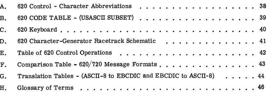
620 Control - Character Abbreviations
620 CODE TABLE - (USASCn SUBSET)
620 Keyboard • • • • . • • • • • • •
[image:8.612.112.545.249.399.2]620 Character-Generator Racetrack Schematic
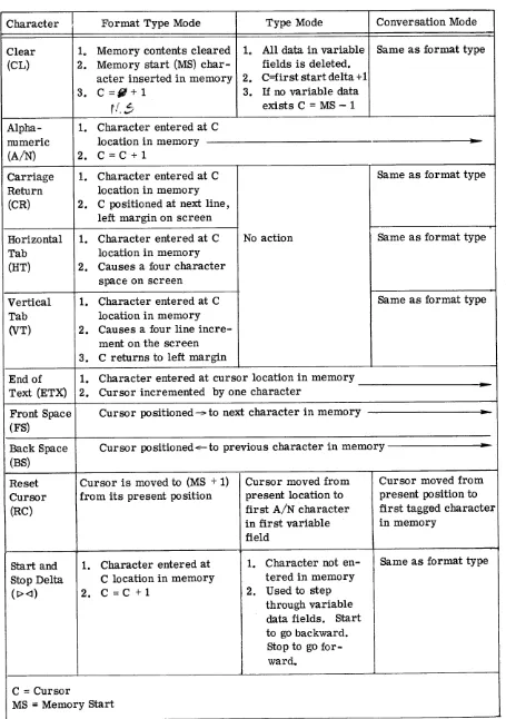
Table of 620 Control Operations
Comparison Table - 620/720 Message Formats • • • • • •
Translation Tables - (ASCn-8 to EBCDIC and EBCDIC to ASCn-8)
Glossary of Terms • . • • • • • • • • • • • • • • • • • • •
v
38 39 40
41
• • • • • 42
• • • • • 43
• • • • • 44
SECTION 1
FUNCTIONAL DESCRIPTION
The 620 is a desk-top stand-alone alphanumeric CRT display. It has a
780-character programmable memory and the optional capability of writing into anyone of
over 2,000 screen locations. Optional edit features include Horizontal and Vertical tabs,
fixed and variable data blocks, and conversation mode. All I/O, editing, memory, display
and power supply components are self-contained in a single terminal package. It is
designed to operate in a remote environment via data set modem connection to a digital
Central Processor.
The 620 keyboard contains alphanumeric and· control function keys as defined by
Appendix C. Data entry via the keyboard causes screen character generation or function
control to occur simultaneously with each keystroke.
Hardcopy may be added to the 620 with the use of the hardcopy adapter and a
tele-printer. The remote user may initiate the copy of either variable block information or
the entire screen content by depressing the function keys associated with those operations.
The computer may poll and initiate a printing sequence by inserting a print command
instruction prior to the ETX of its outbound message.
Data transmission may be on a polled Or a contention basis and can be either
synchronous or asynchronous. A subset of Standard USASCn Code is used for all data
SECTION 2
SYSTEM CONFIGURATION
The 620 System consists of seven functional blocks. They are: 1. I/O Section,
2. Edit Section, 3. Memory Access Section, 4. Memory Section, 5. Display Section,
6. Power Supply, and 7. Keyboard.
I/O SECTION
The function of the I/O Section is to control the transfer of data between a data set
and the 620 System. The I/O Section performs the following functions:
a. Generates character parity and LRC ,on the outbound messages.
b. Checks for parity error and LRC error on incoming messages.
c. Decodes the header sequence and recognizes a specific address for inbound
messages.
d. Encodes the header sequence for outbound messages.
e. Provides logic level conversion and synchronization with the Data Set.
EDIT SECTION
The function of the Edit Section is to perform all editing operations for data
re-ceived from either the keyboard or the computer, and for all data sent to the computer.
The basic edit function provides the capability of entering data on the screen from
left to right and top to bottom through 780 locations. All entry is in format type mode.
Optional Edit features include:
• Horizontal and Vertical Tab -- where a HT causes the cursor to move 4
•
•
screen spaces to the right of the starting location and inserts 1 HT character
on the delay line, and a VT causes the cursor to move 4 lines down (to the
beginning of the new line) on the screen and inserts 1 VT character on the
delay line. All 2,000 + screen locations are accessible with this option.
Conversation Mode -- where each alternate Computer/User entry is
auto-matically positioned at the beginning of a successive line. For example,
the user may enter data on line 1, the computer automatically uses line 2
for its reply; the user then is positioned to line 3 for his next entry, the
computer then replies on line 4, and so on.
Format Mode - - where start delta I> and stop delta <I are used to define variable data-entry fields. Under format control, the user is automatically
prohibited from writing into any fields other than those defined by the start
and stop delta characters. The completion of one field causes the cursor
to automatically move to the beginning of the next available field, (if there is
one available), defined by deltas.
Format Mode keys are provided to allow the use of these Edit options. New
formats are created in Format mode by programming/systems personnel and
can then be used in Type Mode by the operators. HT and VT are considered
Format Mode keys.
MEMORY ACCESS SECTION
The function of the memory access section is to provide the interface between the
620 Memory and the Edit and/or Display sections.
MEMORY SECTION
The function of the memory section is to store all alphanumeric and
function-control characters required to format, edit, and generate a display. Either the total
contents or the delta-defined data blocks of tl1e memory may be dumped to the
DISPLAY SECTION
The function of the display section is to provide a visual representation of the data
stored in memory on the face of the CRT.
POWER SUPPLY
The function of the power supply is to provide the proper voltage and current
requirements to each of the other operating sections.
KEYBOARD
The function of the keyboard is to enable the operator to enter, display, and
trans-mit data through the 620 System. The keyboard is provided with electrical interlock
such that the first key-depressed will be entered into memory. A two key roll-off feature
is provided so that if two keys are depressed, the second key will not be entered into
memory until the first key is released.
There are 42 alphanumeric and special symbol keys, 19 control keys and a space
bar. One of the control. keys is a repeat key which, when depressed along with a second
key, will make repeated entries at a 30 cps rate. Cycle left and Cycle right keys are
also provided to aid rapid cursor movement through screen locations.
SECTION 3
SYSTEM OPERATION
Note: Available 620 Screen matrices include:
64 characters/line by 32 lines (Horizontal Screen)
52 characters/line by 40 lines (Vertical Screen)
84 characters/line by 32 lines (Expanded Horizontal Screen)
These matrix options may be regarded as defining the screen record positions into
which data may be written, and although the following information is based on a 64 x 32
matrix, the same operating ponsiderations apply to the alternative matrices.
,-General
The system operation is described in three sections, (1) I/O Operation, (2) Edit
Operation, and (3) Description of Hard Copy Option. Appendix B identifies the codes that
are used in the 620 system 0
INPUT/OUTPUT OPERATION
GENERAL
The 620 display operates as a remote terminal capable of transmission and reception
of serial data at rates up to 2400 bits per second (bps). The 620 may be connected to a
modem, or a number of 620's may be connected to a modem via a Sanders Associates, Inc.
Model 716 Serial Distributor. The modem being used determines the data transfer rate and
dictates whether data transfer is to be effected in the synchronous or asynchronous mode.
SYNCHRONOUS OPERATION
In the synchronous mode, all characters transferred contain eight bits. Seven of the
eight bits in each character are data bits, and the eighth bit is a vertical parity bit. In
this mode, transmit and receive clocks must be provided to the 620 by the modem. Each
message sent to the 620 must be preceded by at least two successive ASCII SYNC
has been established, there can be no time gaps between bits or words. Synchronous
communication takes place at a rate of 2000 or 2400 bits per second.
ASYNCHRONOUS OPERATION
In the Asynchronous mode, a ten or an eleven bit character is used. This character
consists of seven data bits, one vertical parity bit, one start bit, and one or two stop bits, the exact number of stop bits being a 620 option. Asynchronous communication is also
referred to as "start-stop" communication. SYNC characters are not used, but rather
the start bit of each character is used for synchronization; therefore characters need not
follow each other at a fixed succession rate because synchronization is reestablished with
each start bit. In the asynchronous mode, the 620 uses an internal clock in transmission
and reception of data. Data transmission rates from 110 to 2400 bits per second may be
used. The transmission rate is established by selection of the appropriate jumper
con-nections on the printed circuit I/O card.
COMMUNICATION SEQUENCES
Either of two basic communication sequences is available in the 620. There is a
response sequence and a non-response sequence. These sequences are 620 options. The
basic difference between them is that the response sequence requires use of longitudinal
redundancy checks and message acknowledgements which are not required when the
non-response sequence is used.
In both the response and non-response modes, there are two basic operations which
may be performed. These are the poll and write operations. The poll operation is a
request by the CPU for data from the 620 while the write involves transmission of data
from the CPU to the 620.
In both the response and non-response modes, a poll or a write must be initiated
by the CPU which transmits a four-character command sequence to the 620. This
com-mand sequence may also be referred to as an addressing sequence. The four characters
of this sequence are as follows:
a. SOH (Start of Header)
b. CUA (620 address)
c. X '09' (unused address when addreSSing 620)
The CUA (Control Unit Address) for the 620 may be any of the 128 possible USASCII
characters, but not SYNC or EaT. Each 620 is hard wired to accept one and only one
such address. Any command sequence containing an address other than that associated
with a given 620 will be ignored by that 620. This feature permits use of the 620 with the
Model 716 Serial Data Distributor. If a command sequence is received by a number of
displays, only the display whose address corresponds to the CUA of the command
se-quence will recognize the command.
The DUA (Display Unit Address) or second-level address of the command sequence
is used primarily for compatibility with Sanders 720/360 message structures. The DUA
in a command sequence sent to any 620 must be the 620 code for horizontal tab. (This
is purely arbitrary and, of course, does not result in writing a horizontal tab on the
dis-play screen.) This code will also be the second level address sent by any 620 in
trans-mission.
The command itself is the fourth character of the command sequence. Only two
commands are recognized, the WRITE and the POLL. All other codes received at this
point result in no operation.
There is one case in which an operation may begin without initiation of a command
sequence by the CPU .. If it is desired that a system operate on a contention (i. e.,
non-polling) basis, the 620 contention option may be enabled to allow the display terminal to
transmit data upon operation of the "send" key on the keyboard. With this option enabled,
transmission takes place without receipt of a poll from the CPU.
Non-Response Mode
Write Operation -- In the non-response write operation, the CPU initiates the WRITE
command sequence and follows this immediately with a start of text (STX) character.
Following the STX from the CPU is the message which is terminated by an end of the text
(ETX) character. The entire sequence is then terminated by an end of transmission (EaT)
character from the CPU. The full sequence is as follows:
Computer to 620
SOH
CUA
X 'Og'
WRITE (Command)
STX
Message
ETX
EOT
Poll Operation -- In the non-response poll operaU,on, tPe C~U command sequence
: .. ~:\ ".
e~ds with the POLL character. At this point, if the 6~0 ha,~no message to transmit, it
responds with an EOT. If the 620 does have a message to-transmit, -it responds with STX,
CUA, X '09' , message, ETX, and EOT. The full sequenc~ if;$_ shown ~_ the table below.
In the example shown, the 620 has no message at the end of the' first poll, but does have a
message at the end of the second poll.
Poll No.1
Poll No.2
Computer to 620
SOH
CUA
X '09'
POLL (Command)
f
,
SOH
CUA
X '09'
PQLL (Command)
620 to Computer
i
EOT ,
STX
CUA
X '09'
message
ETX
EOT
Contention ... - In contention, the 620 transmits upon depression of the keyboard SEND
key. The sequence is shown in the following table.
620 to Computer
STX
CUA
X '09' I
Response Mode I Message
ETX
EaT
Write Operation - - The write operation in the response mode is similar to the write
in the non-response mode. It differs, however, in certain respects. After receipt of the
write command sequence, the 620 must respond to the CPU with a negative acknowledge (NAK) or a positive acknowledge (ACK) indicating detection or non-detection of a vertical
parity error in the command sequence. If a NAK is transmitted by the 620, the CPU must, in turn, retransmit the command sequence. If an ACK is sent by the 620, the CPU then transmits the message sequence: STX, message, ETX, LRC. The LRC character is the
longitudinal redundancy character accumulated by a longitudinal redundancy check over all
characters from, but not including, STX up to and including ETX. If a longitudinal or
verti-cal parity error is detected by the 620, it awaits completion of the message from the CPU and then responds to the CPU with a NAK. Otherwise, it responds after message completion
with an ACK. The NAK signals the CPU to retransmit the message while the ACK signals
the CPU to transmit EaT and end the write sequence.
If the 620 responds to the initial write command sequence with an EaT, it is an indication that a 620 hard copy (optional) operation is in process and that the message from the computer cannot be accepted. The computer must re-initiate the command sequence
to execute the write.
The table below shows the write sequence with the various 620 responses:
Computer to 620
Sequence No.1
SOH
CUA
X '09'
WRITE (Command)
t
620 to Computer
EDT (Hard-Copy in Process)
Computer to 620
I
Sequence No.2
SOH
CUA
X 'Og'
WRITE (Command)
I
I
SOH
CUA
X 'Og'
'WRITE (Command)
,
J
STX
Message
ETX
LRC
!
620 to Computer
NAK (Command Sequence Error) I
I
ACK (Proceed) I
I
NAK (Message Sequence Error)
~---~---~I
STX
Message
E'TX
LRC
I
EOT
I
ACK (Proceed)
I
Poll Operation -- The poll command sequence for the response mode is the same as
for the non-response mode. If the 620 has no message it replies to the poll with EOT.
If the 620 has a message for the CPU it sends STX, CUA, X'Og', Message, ETX,
hRq.
The LRC is accumulated from, but not including STX, up to and including ETX;
The CPU responds to the 620 Message with ACK or NAK according to the results of
the longitudinal and vertical parity checks at the CPU interface. A NAK signals the 620
to retransmit the full message while ACK calls for 620 transmission of an EOT to terminate
the entire sequence. The table below illustrates the response poll sequence:
Computer to 620
Sequence No.1 SOH
CUA
X '09'
POLL (Command)
,
,
Sequence No.2 SOH
CUA
X '09'
POLL (Command)
t
I
NAK (620 Message Error)
620 to Computer
,
EOT (no message)
1
,
STX
CUA
X '09'
Message
ETX
LRC
STx
CUA
X '09' Message
ETX
_ _ ~ _ _ _ _ ~+-_ _ _ _ _ _ _ _ _ _ _ _ _ _ ~LRC
ACK (no error) J
EbT
Contention - - In contention, operation is the same as in polling except that the
sequence is initiated by the 620 message transmission. Operation is shown in the table
below.
Computer to 620 620 to Computer
STX
CUA
X '09' Message
Computer to 620
I
NAK (620 Message Error)
I
I
ACK (no error)
I
ERROR CHECKING
620 to Computer
I
STX
CUA
X '09'
Message
ETX
LRC
,
i EOT
In synchronous data communication, the parity bit of each data byte must be such
that odd parity over the byte results. In asynchronous data communication, the parity
bit of each byte must be such that even parity over the seven data bits and one parity
bit results.
The 620 inserts correct vertical parity in all transmitted. characters and checks
vertical parity in all received characters. Receipt in a message sequence from the CPU
of a character whose vertical parity is incorrect results in display of an error character
on the screen.
In the response mode, detection of a vertical parity error in any character from the
CPU results in transmission of a NAK to the CPU after completion of the transmission
from the CPU.
The longitudinal redundancy character used in the response modes is the half-add
of each of the data bits and the parity bit of all characters (except the STX) in the message
sequence. Since the parity bit of the LRC is the half-add of the parity bits of the previous
characters, the LRC does not necessarily contain correct vertical parity. Detection of a
longitudinal redundancy error by the 620 results in the transmission of a NAK to the CPU.
Also the CPU should send a NAK to the 620 if such an error is detected in a 620 message
sequence transmission.
EDIT OPERATION
GENERAL
The 620 system has three modes of data entry, defined as 1. Format Type, 2. Type,
and 3. Conversation Type. The standard 620 is capable of Format Type mode only. Type
mode and Conversation Type mode are available as options.
FORMAT TYPE MODE (FT)
The system is placed in Format Type mode upon initial system tu.L'n on and remains
in this mode at all times until either a Type mode or Conversation Type mode character is
entered from either the keyboard or CPU. The 620 can be returned to Format Type mode
by entering a Format Type character.
(FT) Clear (CL) - Upon receipt of this code the contents of memory are cleared and
the Memory start (MS) character is inserted in the memory by the hardware. The cursor
is positioned at MS+ 1.
(FT) Alphanumeric Characters - Each character is entered into memory at the present
cursor location. Cursor is front spaced ooe position except in the case where the character
is entered into the location immediately preceding memory start (MS-1). In this case, the
cursor remains at this location. All alphanumerics in memory are displayed except an
alphanumeric inserted into the 65th pOSition on a line.
(FT) Carriage Return (CR) - Same as alphanumeric, except that the CR is not
dis-played. This character moves cursor down one line and returns cursor to left margin. If
a CR is not inserted in memory an automatic carriage return is accomplished ·on the display
after 64 characters have been inserted on one line and one memory location corresponding
to the 65th character position on a line is lost.
(FT) Horizontal Tab (HT) - This character is entered into memory at the present
cur-sor location. Curcur-sor is front spaced one position in memory except in the case where the
character is entered into the location immediately preceding memory start (MS-1). In this
case, the cursor remains at MS-1. The HT character will cause a four-character space to
occur on the display. The HT character is optional and if sent to the 620 without the option, it will be disregarded. If an HT character is entered into the 61st through 64th character
(FT) Vertical Tab (VT) - Same as HT except that the VT will cause the display to
increment four lines and return to the left margin.
(FT) Start Delta (t» and Stop Delta (<I) - These characters are entered into memory
at the present cursor location. Cursor is front spaced one position except in case where
the character is entered into location MS-l. In this case, the cursor remains at MS-l.
The start and stop characters are only available with the Format Option and if sent to the 620 without the option, will be disregarded.
(FT) End of Text (ETX)- This character is entered into memory at the present
cur-sor location. Curcur-sor is front spaced one position except where ETX is entered into location
MS-l. In this case cursor remains at MS-l.
Cursor Moves - The following characters accomplish cursor movements only and are
not entered into memory.
(FT) Reset Cursor (RC) - Cursor is moved from present position to MS+ 1.
(FT) Front Space (FS) - The Cursor is moved forward one position except in case
where present position is at MS-l. In this case no cursor action is accomplished.
(FT) Back Space (BS). - The cursor is moved backward one position except in case where present position is at MS+ 1. In this case, no cursor action is accomplished. The
back space character is not normally used in CPU messages.
(FT) Send (SP) - This character is not inserted into memory. Upon receipt of this
code, the 620 enters an output routine. The cursor is moved from its present position to
MS+l and the 620 awaits a CPU poll. Upon receipt of a poll, all characters in memory, up
to ETX are sent and cursor is left on ETX character at end of operation. If no ETX is
found, all characters in memory, including nulls, are sent and the cursor is left at location
MS-l. If the 620 contention option is selected, the poll from the CPU is not required.
TYPE MODE (TP)
Type mode is available as an option in the 620 system, (Format Option). The Format
Option enables the 620 to establish a two-block configuration, one fixed and one variable.
This option requires the use of Format Type mode and Type mode operations. The fixed
block is established in Format Type mode and the variable data is entered in Type mode.
A variable field is defined as that data between a start delta character and a stop delta
character. Any number of variable fields may be established in Format Type mode by the
use of the start and stop delta characters. The 620 is placed in Type mode by the receipt
of a Type character and remains in Type mode until receipt of a Format Type or
Conversa-tion Type character. Upon receipt of a Type mode character the cursor is posiConversa-tioned in the
first character position of the first variable field in memory, (i. e., I> + 1). If there are no variable fields in memory the cursor will stop on MS-1.
,~6
(TP) Clear (CL) - Upon receipt of this code all data in variable fields is deleted from memory. The delta characters are not deleted. The cursor is left at the first I> + 1~ sor is left at MS-1.
(TP) Alphanumeric Characters - Character is entered into memory at the present
cursor location. The cursor is front spaced one character if the character is entered into
a location not immediately preceding a stop delta or MS. If the character is entered into a
location immediately preceding a stop delta, the cursor is front spaced to the first
alpha-numeric character position in the next variable field in memory. If the character is entered at MS-1, the cursor remains at this position.
(TP) Carriage Return (CR) - No operation
(TP) Horizontal Tab (HT} - No operation
(TP) Vertical Tab (VT) - No operation
(TP) Start Delta (1)) and stop Delta (<J) - These characters are used in Type mode to
accomplish automatic cursor movement and are not entered into memory. The stop delta
is used, after resetting the cursor, to address a particular variable field. The cursor will
advance one variable field for each stop delta programmed. The start delta is used by a
keyboard operator. in Type mode to back the cursor through each variable field. The cursor
will back up one variable field for each start delta programmed. The start delta is not
nor-mally used in a CPU program as extensive timing restrictions result. The stop delta may
also be used in Type mode to reduce transmission requirements. For example, if a
format-ted block consists of 30 characters and only 10 characters are actually used in the variable
field, a stop delta may be used to position the cursor to the beginning of the next variable
field, instead of programming 20 front spaces or 20 space codes.
(TP) Start Delta (t» - Upon receipt of this code the cursor is moved from its present
no stop delta characters in memory, the cursor will stop at location MS+l, the second
time through memory.
(TP) Stop Delta (<1) - Upon receipt of this code the cursor is moved from its present
location to the first alphanumeric character location in the following variable field in
mem-ory. The cursor will search past MS looking for the following start delta character in
memory. If there are no start delta characters in memory, the cursor will stop at
loca-tion MS-l, the second time through memory. < ' . . : J
.
Iv~
t-
ef,
fvv
d(TP) End of Text (ETX) - Same as Alphanumeric characters in Type mode. I~.-.i)-rl
C
/)C/
Cursor Moves - The following characters are not entered into memory but a~e used
to accomplish cursor movements. The back space is not normally used in a CPU program
as extensive timing restrictions result.
(TP) Reset Cursor (RC) - Upon receipt of this code, the cursor is moved from its
present location to the first alphanumeric character location in the first variable field in
memory. If there are no variable fields, the cursor is positioned at MS-l.
(TP) Front Space (FS) - If the cursor is positioned on the last character location in
a variable field, it is automatically front spaced to the first character location in the next
variable field. If the cursor is positioned at MS-l, it remains there. If the cursor is
posi-tioned neither at the last character location in a variable field nor at MS-l, it is front spaced
one position.
(TP) Back Space (BS) - If the cursor is positioned on the first character location in
a variable field it is back spaced to the last character location in the preceding variable
field. If the cursor is positioned at MS-l, it remains there. If the cursor is positioned
neither on the first character location in a variable field nor at MS-l, it is back spaced
one position.
(TP) Send (SP) - This character is not inserted into memory. Upon receipt of this
code the 620 enters an output routine. The cursor is moved from its present location to the
first alphanumeric position of the first variable field in memory and awaits a CPU poll.
Upon receipt of poll, all alphanumeric data located in all variable fields including all stop
deltas are sent to the CPU up to ETX and cursor is left on the ETX character. During the
output routine, the cursor is automatically advanced from the end of one variable field to
the beginning of the next variable field. During the automatic cursor advance between
vari-able fields, null characters may be sent to the CPU dependent on the number of character spaces
between variable fields. If nulls are required, they will be automatically generated by the
620. If no ETX character is encountered, the cursor is left at location MS-1. If the 620
contention option is selected, no poll is required from the CPU.
CDNVERSATION TYPE MODE (CT)
Conversation Type mode is available as an option in the 620 system. This option
enables the 620 to transmit and receive sequential data down the face of the CRT without
disturbing previously transmitted or received data.
Conversation Type mode is accomplished by tagging each character as it is entered
into memory. Both CPU data and keyboard data are tagged. Each message segment is
terminated with an ETX.
When accomplishing a send routine, all tagged characters up to ETX are sent to the
CPU. Upon receipt of an ACK from the CPU, all tag bits in memory are cleared, the ETX
in memory is changed to a CR and the cursor is positioned on the CR+1 memory location.
If a NAK is received from the CPU, the 620 will not clear the tag bits nor change the ETX
to a CR, but will re-transmit the tagged characters and will repeat this sequence for each
NAK received until an ACK is received. When accomplishing a write routine to the 620,
each CPU character is tagged when entering memory. If the 620 received the message
successfully (i. e., no LRC or parity errors) it will send an ACK to the CPU, clear all tag
bits and change the ETX character terminating the CPU message to a CR and front space
the cursor one position. If an error is detected in the received message, the 620 will send
a NAK to the CPU, position the cursor on the first tagged character location, and clear all
tagged characters in memory, in anticipation of re-transmission of the message by the CPU.
The 620 is placed in Conversation Type mode by the receipt of a Conversation Type
character and remains in Conversation Type mode until receipt of a Format Type or Type
character.
(CT) Clear (CL) - Identical operation as in Format Type mode.
(CT) Alphanumeric Characters - Same as Format Type operation.
(CT) Carriage Return (CR) - Same as Format Type operation.
(CT) Horizontal Tab (HT) - Same as Format Type operation.
(CT) Vertical Tab (VT) - Same as Format Type operation.
(CT) End of Text (ETX) - Same as Format Type operation.
Cursor Moves - The following characters accomplish cursor movements only and are
not entered into memory.
(CT) Reset Cursor (RC) - The cursor is moved from its present position to the first
tagged character in memory. If there are no tagged characters in memory, the cursor is
positioned at MS-1.
(CT) Front Space (FS) - Same as Format Type operation.
(CT) Back Space (BS) - Same as Format Type operation.
(CT) Send (SP) - This character is not entered into memory. Upon receipt of this
code, the 620 enters an output routine. The cursor is moved to the first tagged character
in memory and awaits a CPU poll. Upon receipt of a poll all tagged characters up to ETX,
or if no ETX, all tagged characters up to MS are sent to the CPU. Other operations are
accomplished dependent on an ACK or NAK reply from the CPU. (See explanation under
Conversation Type mode above.) If 620 contention option is selected, no poll is required
from the CPU.
DESCRIPTION OF HARD-COPY OPTION
The function of this option, named the Hard-Copy I Option, is to produce a permanent
record of data displayed on the Model 620 terminal by copying the data on a Model 33 or
Model 35 Teletype.
HARD-COPY OPTION COMPONENTS
The Hard-Copy I Option consists of the following components:
a. Hard-Copy Buffer I
b. Printer
c. Hard-Copy Data Transmission Cable
d. Modified Keyboard
Hard-Copy Buffer I
The function of the Hard-Copy Buffer I is to accept data from the 620 memory and to
control the transfer of the data to the Hard-Copy Printer. The data is transferred serially
at the rate of 110 bits per second (10 characters per second). Each character transferred
is composed of eleven bits: 1 start bit, 7 USASCn data bits, 1 unused parity bit, and 2 stop
bits.
Printer
The printer used with the Hard-Copy I Option is either an ASA 33FR or an ASA 35SP.
It is a receive only device which accepts data at a rate of 110 bits per second.
Transmission Cable
A two-wire, twisted-pair cable is provided with the Hard Copy I Option to transfer
the data from the 620 to the teletype. The maximum length of this cable is 1000 feet.
Keyboard
The standard 620 keyboard is modified with the Hard-Copy I Option to include a Copy
key whose function is to enable an operator to initiate a hard-copy routine. A hard-copy
busy lamp is provided that illuminates upon depression of the Copy key and extinguishes
upon completion of the copy routine.
HARD-COPY FUNCTIONAL OPERATION
A copy routine may be initiated from either the CPU or the 620 keyboard. In order
for the CPU to initiate a hard-copy routine the Copy code (0000011 in bits 1 through 7
respectively) must be contained in the body of the message, (i. e., anywhere between STX
and ETX) , of a normal CPU write routine. When the message has been positively
acknow-ledged by the 620, the copy routine will be initiated. In order for an operator to initiate a
hard-copy routine he must depress the Copy key on the 620 keyboard.
The hard-copy routine is under control of the 620 Edit Logic and therefore the display
may not be used while the copy routine is in process. Both the 620 I/O section and the
key-board are interlocked for the duration of the copy routine. During a copy routine, the 620
I/O section will respond to all write and poll requests with an EOT.
A copy routine will terminate upon detection of either an end-of-text (ETX) or a
Memory Start (MS) character in the 620 memory, whichever occurs first.
Hard-Copy Code Conversions
The following code conversions are accomplished by the 620 hardware during a
hard-copy routine:
a. Start Delta (I» is converted to a space code.
b. Stop Delta (<1) is converted to a space code.
dll Vertical Tab (VT) is converted to one carriage return (CR) and four line-feed
codes.
e. Carriage Return (CR) is converted to a carriage return plus a line-feed code.
NOTE
A carriage return and line-feed code is auto-matically inserted by the 620 hardware at the beginning of each hard-copy routine.
Hard-Copy Modes of Operation
There are two modes of operation for the 620 Hard-Copy routine. Copy Mode 1 copies
all data on the 620 CRT and Copy Mode 2 copies only the variable data (i. e., the data between
Start and Stop Deltas). The selection of the appropriate copy mode is determined by the 620
mode of operation. When the 620 is in Format Type (FT) or Conversation Type (CT) mode,
Copy Mode 1 is selected by the hardware. When the 620 is in Type (TP) mode, the
hard-ware selects Copy Mode 2.
Mode 1 Operations: Copy Mode 1 copies all data sequentially received from the 620
with the code conversions as outlined in the paragraph above entitled "Hard- Copy Code
Conversions" .
Mode 2 Operation: Copy Mode 2 copies all data sequentially received from the 620
with the code conversions as stated in the paragraph above entitled "Hard-Copy Code
Con-versions" as well as with the following conversions:
a. All alphanumeric data (i. e., this does not apply to CR, VT, and HT) received
within the following boundaries are converted to space codes:
1., All A/N data between Memory Start (MS) and the first Start Delta {I».
2. All A/N data between a Stop Delta (<1) and subsequent Start Delta (t».
3. All A/N data between the last stop Delta (<1) and Memory Start (MS).
b. All null codes received between a Start Delta (t» and the following Stop Delta (<1)
are converted to space codes.
SECTION 4
PROGRAMMING CONSIDERATIONS FOR USE OF 620 WITH IBM SYSTEM/360
REMOTE TRANSMISSION - (2400 bits per second or less)
In general, IBM provides a read/write routine common to all supported TP devices
plus a number of Device Dependent Modules (DDM' s), each of which consists of a tabular
set of constants uniquely defined for a supported device. At OPEN time, a logical
connec-tion is established between the appropriate DDM, the I/O control block (DCB, DTFQT, or
DTFBT), and the common read/write routine. Subsequent I/O requests, via the language
(i. e., macro instruction) facilities of the IBM access method used, cause the common read/
write routine to generate channel programs appropriate to the device to be communicated
with by using the reference information tabulated in the linked DDM.
The 620 Display Terminal becomes fully supported under any IBM access method in
this category by simply using the appropriate Sanders - furnished Device Dependent
Module(s). The Sanders - furnished DDM(s) may be incorporated and put to use in a
num-ber of ways. For example, in the event that the only display terminal type to be used in a
particular installation is the Sanders 620 Data Display System, it is only necessary to
re-place the DDM intended for the IBM 2260 with the Sanders - furnished DDM for the 620. The
full facilities of the access method now become available and can be used exactly as described
in the appropriate IBM publication.
OS BTAM - (REMOTE CONNECTION)
The following discussion describes the steps one must follow to use the 620 Data
Dis-play System with OS BT AM.
The problem programmer must provide a Data Control Block (DCB) for each line
group to be used. He must initialize each DCB by using the IBM OPEN macro-instruction
and should insure that each OPEN operation was successful. Mter execution of the OPEN
opened successfully. If the user has not replaced the catalogued IBM 2260 DDM (IGG019M3)
in SYSl.SVCLIB, he then must issue the DOPEN macro-instruction (provided by Sanders)
to set up the ne<;essary linkages between OS BTAM, one of the Sander's DDM's, and the
DCB's in his program. (See Sanders First-Level Support Manual for a detailed description
of the DOPEN macro-instruction.) If replacement of the IBM 2260 DDM is chosen, the IBM
utility ILEffiOSUP must be run to update the TTR's in the SVCLIB directory.
In addition to using the DOPEN macro-instruction, the problem programmer should
use the EBCDIC to ASCIT-8 and ASCIT-8 to EBCDIC translate tables provided by the Sanders'
TABLES macro-instruction. (See Sanders First-Level Support Manual for a detailed
description of the TABLES macro-instruction.) In addition to the normal alphanumerics,
these tables contain the special edit and function characters unique to Sanders Displays.
(See Appendix F of this publication.)
OS QT AM - (REMOTE CONNECTION)
To use the 620 Display System with OS QTAM, the user should do the following:
a. Use the Sanders-supplied tables, provided by the TABLES macro-instruction,
for translating incoming and outgoing messages. (See Sanders First-Level Support Manual
for a detailed description of the TABLES macro-instruction.)
b. Ensure that when the BTAM read/write routine is invoked by QTAM for an I/O
operation, the routine will construct channel programs compatible with the Sanders 620
Dis-play System.
To accomplish step "a" above, two macro-instructions, one named TRANS provided
by IBM and another named TABLES provided by Sanders, may be used. (See IBM
publica-tion C30- 2003 for an explanapublica-tion of TRANS.)
There are two methods available for accomplishing step "b":
Method 1:
If the user is operating in a non-mixed environment, i.e., is using one model-type of
Sanders Display, he may replace the IBM 2260 DDM with the appropriate Sanders-supplied
DDM by link-editing the Sanders DDM as a replacement for the module IGG019NR in SYSl.
SVCLIB and running the IBM utility program IEHIOSUP to update the TTR's in the SVCLIB
directory.
Method 2:
If on the other hand, the user wishes to retain the capability for operating IBM 2260's
or he wishes to operate more than one model type of Sanders display, he must first
link-edit the Sanders DDM into SYSl. LINKLIB. Secondly, he must employ the DOPEN
macro-instruction to perform the necessary DCB initialization. Finally, he must furnish the
link-age editor control statements to include the modules in his program.
NAME OPERATION OPERAND 72
OPENIO OPEN (DISK, (INOUT), X
LINE2260, (INOUT), X
LINE620, (INOUT, X
IDLE))
DOPEN LINE620, X
DEVTYPE= (620, X QTAM)
LA 7, LINE620
STARTLN (7)
Note that using the IDLE parameter in the "options" field associated with the Sanders
display line group defers polling of the line group to allow DCB initialization to be performed
by DOPEN. Even if IGG019NR is replaced, the IDLE option should be used.
Subsequently, polling is initiated by STARTLN. (See Sanders First-Level Support
Manual for a detailed description of the DOPEN macro-instruction.)
To obtain automatic linking of the DOPENed DDM's, ensure that the NCAL option is
not specified and that the JCL for the linkage editor includes the following DD card:
NAME OPERATION OPERAND
//SYSLIB DD DSNAME = name*, X
DISP = OLD
*
name=
the name of the data set containing the DDM.DOS BTAM - (REMOTE CONNECTION)
a. Use the translate tables provided by Sanders to convert incoming and outgoing
messages to the appropriate codes.
b. Ensure that the DOS BTAM control program will access the appropriate
Sanders-supplied Device Dependent Module (DDM) for contructing channel programs.
c. Ensure that all DTFBT's which refer to Sanders display line groups have been
properly initialized.
To accomplish the first requirement, a translate table generating marco-instruction
named TABLES has been supplied. (See Sanders First-Level Support Manual for a detailed
d~scription of the TABLES macro-instruction.)
The second and third requirements as stated above may be met by using the DOPEN
macro-instruction. (See the description of the ooPEN macro-instruction in Sanders
First-Level Support Manual.)
DOS QTAJ.i/1 - (REMOTE CONNECTION)
To use Sanders 620 Display System with DOS QTAM, the user should do the following:
a. Use the translate tables provided by Sanders to convert incoming and outgoing
messages to the appropriate codes.
b. Ensure that the DOS QTAM control program will access the appropriate
Sanders-supplied Device Dependent Module (DDM) for constructing channel programs. (Refer to the
description of the DOPEN macro-instruction in Sanders First-Level Support Manual.)
To accomplish the first requirement, a translate table generating macrO-instruction,
TABLES, is supplied by Sanders. (See Sanders First-Level Support Manual for a detailed
description of TABLES.)
There are two methods available for accomplishing step "b":
Method 1:
If the user is operating in a non-mixed environment, i. e., is using one model-type of
Sanders Display, he may replace the IBM 2260 DDM for QTAM with the appropriate
Sanders-supplied DDM in the relocatable library.
-Method 2
If the user wishes to retain capability for operating IBM 2260's or he wishes to operate more than one type of Sanders display, he must employ the DOPEN macro with
DEVTYPE
=
({620 or 720}, Q [TAM]) to perform the necessary DTFQT initialization.DEVICE DEPENDENT MODULE (DDM) DESCRIPTION
A number of Device Dependent Modules have been designed by Sanders to provide I/O
processing compatibility between OS BTAM/QTAM, DOS BTAM/QTAM, and Sanders Display
Systems in a remote environment.
DETAILED MESSAGE STRUCTURES - Remote Operation
Messages received from a 620 terminal by the CPU have the following format:
)C , I
STX f\ tzr~
CUA
X '09'
r;.~~vvJ'
-/0
IX, It.;
A )
First Text Character
Last Text Character
ETX
r
1p-r3
ILRC
tOT Xlp~1
Start of Text
Control Unit Address
620 Display Address
Variable length message from 620 memory
End of Text
Longitudinal Redundancy Character
NOTE
A The LRC character is sent by the 620 system 'but is not transferred into main storage.
Messages sent to a 620 terminal from the CPU have the following format:
STX Start of Text
Format type or other mode -change character
First Text Character
Variable length message from user's I/O area
ETX
LRC
End of Text
Longitudinal Redundancy Character
NOTE
The LRC character is generated by the transmission control unit - no user action is required.
ACCESS-METHOD DEPENDENT INFORMATION
Access Method Messages from 620 to CPU Messages to 620 from CPU
OS BTAM STX appears in first-character STX and FT on output are provided
OS QTAM
DOS BTAM
DOS QTAM
USING A DDM
position of u~ area followed by by the DDM. The user can start CUA, X '09' (display address), and his message in position one of his
message text; terminated by an buffer. If a mode other than FT is
ETX. desired, the user can start with
another mode-change character.
Same as above.
Same as OS BTAM.
Same as OS QTAM.
Same as above.
Under DOS BTAM the user must
provide his own STX character and
FT or other mode-change character.
The message must terminate with
an ETX.
Same as OS QT AM.
A user may obtain the services of a particular DDM in one of two ways:
a. He may replace the appropriate IBM 2260 DDM with the desired Sanders DDM,
renaming it with the name of the 2260 DDM.
b. Use the DOPEN macro-instruction (See Sanders First-Level Support Manual
for a detailed explanation of DOPEN).
The DEVTYPE parameter of the DOPEN macro-instruction should be coded as follows
to obtain the services of a particular DDM:
DEVTYPE
=
(model-number, access-method)Model- Number
720 or 620
720 or 620
OS-DDM'S
(BTAM) DDMOSNO 1 (QTAM) DDMOSQO 1
MESSAGE PROCESSING MACROS
Access- Method
BTAM
QTAM
DOS-DDM'S
DDDOSNOI DDDOSQOl
A number of message processing macro-instructions have been designed by Sanders
to assist the user of Sanders Data Display Systems in handling his message processing
functions. Of particular interest to the 620 user are two macros named EDITMOVE and
TABLES.
EDITMOVE MACRO-INSTRUCTION
The facilities provided by EDITMOVE are embodied in the EDITMOVE
macro-instruction and the EDITMOVE processor. Both the macro-macro-instruction and the processor
are equally compatible to OS and DOS users. The EDITMOVE processor will move a stream
of input characters to an output area and perform specified serial editing operations in
tran-sit. The range of editing operations performed with a single pass through the input stream
includes substitutions, insertions, and deletions caused by user specified characters and/or
character- string sequences encountered in the input stream. If the editing operations- to be
performed are known in advance (i. e., at compile time), the EDITMOVE macro-instruction
can be used to specify the desired editing operations in a systematic way with standard
nota-tion convennota-tions. If editing speCifications must be derived at execution time, parameters
may be dynamically constructed for the EDITMOVE processor without using the EDITMOVE
macro-instruction. (See Sanders First-Level Support Manual for a full explanation of
TABLES MACRO-INSTRUCTION
Use of the TABLES macro-instruction causes generation of an EBCDIC to ASCn-8
translate table and/or the generation of an ASCn-8 to EBCDIC translate tableo (See
Trans-lation Tables in Appendix F of this publication.) These tables should be used to translate
messages sent to and received from a Sanders 620 Data Display System. (See Sanders
First- Level Support Manual for a full explanation of the parameters for the TABLES
macro.)
SECTION 5
TIMING CONSIDERATIONS FOR 620 CONTROL OPERATIONS
Timing considerations within the 620 System are mode dependent and thus will be
discussed on an operating mode basis. The memory access time of the 620 is 5.55
milli-seconds and the majority of functions are able to be completed in one memory cycle time.
Some control functions will require additional time to complete their operation in certain
modes and it will therefore be necessary to program null characters. The number of null
characters required is a function of the mode (asynchronous or synchronous) and
sion rate (110, 1000, 1200, 1800, 2000, 2400, etc.) of data transmission. The
transmis-sion time taken by the number of null characters used must equal the fixed response time
required to complete the desired 620 control operation. To facilitate the editing operations
required for null character insertion in outgoing messages, use of the Sanders-furnished
EDITMOVE macro-instruction (described elsewhere in this publication) is recommended.
The formulas below will enable the programmer to determine the worst case. number
of nulls to insert in a message for each control character. In some instances it will be noted
that the number of nulls needed must be partially estimated due to unpredictability of the
contents of the 620' s memory.
NOTE
The notation (X)Y means "Y, in mode X" , where X is a mode change character (i. e., FT, TP, or CT).
How to Use the Formulas: Unless otherwise stated the quantity of nulls represented
should be inserted following the given character in the message.
a. Determine the value of f from the table applicable to the current transmission
mode and transmission rate.
b. f represents a number dependent on transmission characteristics which is then
always be rounded down to a whole number. (e. g., if the final sum or product of a calcul-ation equals 6.86 nulls, this may be rounded down to 6 nulls.)
c. To determine the fixed response time required for any of the listed 620 control
operations which require nulls, set f equal to 5.55 milliseconds. Thus (FT) BS
=
f=
5.55milliseconds 0
CONTROL OPERATIONS TIMING
FORMAT TYPE MODE
The following timing constraints are placed on programming the 620 in Format
Type (FT) mode:
(FT) CL
=
no null requirement (FT)A/N = no null requirement{FT)CR
=
no null requirement(FT)HT = no null requirement
(FT)VT = no null requirement
(FT) I> and <1 = no null requirement
(FT)ETX
=
no null requirement (FT)RC=
no null requirement(FT) FS
=
no null requirement(FT)BS
=
f after each BS in FT mode (FT)SP=
no null requirementTYPE MODE
The following timing constraints are placed on 620 programming when in Type (TP)
mode:
(TP)CL
=
5 f after each CL in TP mode(TP)A/N
=
no null requirement except when the A/N entry is made in a location immediately preceding a Stop Delta (<1) character. In this case, the cursor is automaticallyadvanced to the beginning of the next variable field, and the null requirement equals f/260
~'"""'. r · ... " ,'"
X (number of characters through which cursor mustadvance) .
.:5
-t-
i
<.
~/.~ (TP) CR = no operation in TP mode(7
r' ()
/f--~.'"(
'/ (TP)HT=
no operation in TP mode{TP)VT
=
no operation in TP mode(TP) l> and <1: The timing requirements with respect to Start and stop Delta
are functions of the format already established in memory.
{TP)l>
=
f for each character through which the cursor must backspace. The use of this code requires that a variable number of nulls be programmed depending uponthe number of positions in memory through which the cursor is automatically backspaced.
The exact number of backspaces is a function of the present cursor location and the
loca-tion of the preceding stop Delta (<1) character in memory.
{TP)<t
=
f/260 X (number of characters through which cursor must advance). The use of this code causes an automatic forward space of the cursor which can beaccom-plished in 21.3 microseconds per character position. The exact number of forward spaces
is a function of the present cursor location and the location of the following Start Delta (l»
character in memory.
{Tll)ETX
=
no null requirement{TP)RC
=
f/260 X (number of characters through which cursor must advance); the total number of characters is measured from MS (Memory Start) to the first StartDelta (l» character in memory.
(TP) FS
=
no null requirement except when the FS entry is made in a locationimmediately preceding a Stop Delta (<1) character. In this case, the cursor is automatically
advanced to the beginning of the next variable field, and the null requirement equals f/260
X (number of characters through which cursor must advance).
(TP) BS
=
f after each BS in TP mode except when the cursor is located immedi-ately following a Start Delta (l» character. In this case, the null requirement equals f foreach character through which the cursor must backspace to get to the last character of the
preceding variable field, as in the operation of (TP) l> above.
(TP)SP
=
no null requirementCONVERSATION TYPE MODE
The following timing constraints are placed on 620 programming when in Conversation
Type (CT) mode:
(CT)CR
=
no null requirement(CT)HT
=
no null requirement(CT)VT
=
no null requirement(CT) I> and <I
=
no null requirement(CT)ETX
=
no null requirement(CT)RC
=
f/260 X (number of characters through which cursor must advance);the total number of characters is measured from MS (Memory Start) to the first character
in the current message.
(CT)FS
=
no null requirement(CT)BS
=
f after each BS in CT mode(CT)SP
=
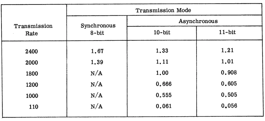
no null requirementTABLE OF f VALUES
Transmission Mode
Transmission Synchronous Asynchronous
Rate 8-bit 10-bit 11-bit
2400 1. 67 1.33 1021
2000 1.39 1.11 1.01
1800 N/A 1.00 0.908
1200 N/A 08666 0.605
1000 N/A 08555 08505
110 N/A 0.061 00056
[image:40.612.92.539.372.577.2]SECTION 6
INTERFACE REQUIREMENTS AND CHARACTERISTICS
HARDW ARE INTERFACE
The 620 Data Display System is compatible with and meets the requirements of EIA
Standard, RS-232-B. The 620 contains selectable interfaces consisting of jumper wire
patching on the Modem Control Card enabling it to interface with either a data set or the
Sanders 716 Serial Distributor.
DATA SET INTERFACE
Examples of typical data sets that the 620 is designed to interface with are the
follOwing AT & T data sets:
a. Modell03A
b. Modell03F
c. Model202C
d. Model202D
e. Model201A
f. Model201B
SERIAL DISTRIBUTOR INTERFACE
The 620 may also be interfaced with the Sanders 716 Serial Distributor. The 716
Serial Distributor enables the 620 to be located up to 1000 feet away from the data set
and allows multiple, (up to sixteen), 620's to be connected to a single data set. The
pri-mary difference in the interface is that the Signals are +5 V and 0 V instead of the data set
levels of ±15 V. When the Serial Distributor is used, the Data Terminal Ready Signal
origi-nates in the Serial Distributor and is not individually carried from each 620 to the Serial
SOFTWARE INTERFACE WITH IBM SYSTEM!360
The following are special system generation considerations for interface of the
Sanders 620 Data Display System with IBM System/360:
SPECIAL OS SYSTEM GENERATION CONSIDERATIONS
BTAM and QTAM - Remote Connection
The following system generation macros should be completed for utilization of the
620 with BTAM and QTAM:
As Required
For 731
*For 620 Line Groups
NAME OPERATION
DATAMGT
TELCMLIB
IOCONTRL
IODEVICE
IODEVICE
OPERAND
-UNIT = 2701, ADDRESS =
:xx
UNIT = 2260, ADAPTER = IBM 3,
MODEL = 1, ADDRESS = XXY
UNIT = 2260, ADAPTER = IBM 3,
MODEL = 1, ADDRESS = XXY
'*(Up to eight 620 line groups per 731 Data Communications Buffer)
:xx
= channel number and channel position (731)Y = 731 - line position (for 620 display terminal or 716 serial distributor)
Caution
X
X
In choosing line addresses for graphic devices, care must be taken to select an
address which is acceptable to the channel. An IBM representative should be consulted
to determine which addresses have been implemented on the channel you wish to use for
the I/O connection.
SPECIAL DOS SYSTEM GENERATION CONSIDERATIONS
BTAM and QTAM - Remote Connection
The DVCGEN system generation macro should be completed as follows for utilization
of the 620 with BT AM and QT AM:
NAME OPERATION OPERAND
DVCGEN CHU.N
=
X' cuI' , DVCTYP=
2701where
c = 0 for Multiplexor Channel
u = 731 Data Communications Buffer number (O-F)
I = 731line number (for 620 display terminal or 716 serial distributor)
Caution
In choosing line addresses for graphic devices, care must be taken to select an
address which is acceptable to the channel. An IBM representative should be consulted
to determine which addresses have been implemented on the channel you wish to use for
SECTION 7
INSTALLATION PLANNING DATA
INPUT POWER REQUIREMENTS
The 620 operates entirely from the following source:
117 VAC ± 10 percent
48 to 62 Cycles per second
200 Watts
PHYSICAL SPECIFICATIONS
DISPLAY TERMINAL
The model 620 Data Display Terminal is a self-contained desk-top unit. The display
cabinet is mounted on a 4-1/4 inch high base at an angle which allows a normal reading
attitude when the display terminal is located on a desk top.
Dimensions and Weight
Height
Width
Depth
Weight
Connectors
CABINET
14 inches
16-1/2 inches
20-1/2 inches
BASE
4-1/4 inches
16-1/2 inches
20-1/2 inches
50 pounds (approximate)
Two female connectors are mounted on the base of the display terminal. One of
these connectors is to connect to either the keyboard or cable from the keyboard. The
other is an output connector for connection to a data set.
C.ables
A seven-foot three-prong AC cord and a ten-foot data set cable are provided with
the 620.
KEYBOARD
The keyboard is in the form of an alphanumeric typewriter keyboard with 64
alpha-numerics and 12 additional function keys. An optional ten-foot cable with connector may
be supplied to connect the keyboard to the display terminal. All electronics are contained
within the keyboard.
Dimensions and Weight
Height
Width
Connectors
4-1/4 inches
16-1/2 inches
Depth
Weight
6-7/8 inches
9 pounds (approximate)
A single 37 -pin male connector on the rear of the keyboard connects either directly
to the display terminal or to a cable with a mating connector. This connector carries all
input and output signals.
Function Keys
There are 16 function keys, four of which are spare.
EDIT FUNCTIONS I/O FUNCTIONS CURSOR CONTROL OPTIONS
Format Type (FT) Send (SP) Reset Cursor (RC) Copy (CPY)
Type (TP) ETX (End of Text) Cycle Left
Conversation Type (CT)
t> (Start Delta)
<1 (Stop Delta)
Clear (CL)
ENVIRONMENTAL CONDITIONS
OPERATING
Temperature:
Humidity:
Barometric Pressure:
STORA