bachelor thesis
“Photovoltaic bubble module”
author information tessa christiaanse noorderhagen 46c 7511 em enschede s0149446
education information industrieel ontwerpen universiteit twente
faculteit der construerende technische Wetenschappen Postbus 217
7500ae enschede
comPany information enea Portici
largo enrico fermi 1 80055 Portici mentors
foreWord
you just started reading the report about my bachelor thesis at twente university.
for this thesis, i went to naples in italy to design a so called “photo-voltaic bubble module”. near naples enea in Portici is situated and there i have worked on my research to photovoltaics and my design of the bubble module. enea is a research center to photovoltaics and therefore was the optimal working environment because of all their experience.
i have learned a lot about the subject and working and living abroad was a very instructive contribution to the total learning experience.
i would like to start with thanking my boyfriend, my parents and my friends in naples and in the netherlands for listening and motivating me when i needed it.
then, i would like to thank my mentor at enea, alessandra scognami-glio, who was very helpful at every moment. especially the building analysis phase i could not have done without her help.
i also want to thank angele reinders for her help from the nether-lands in every phase of the project.
for the analysis, i have done an interview among architects and i want to thank them for their collaboration.
summary
enea in Portici develops new products in the sector of technologies for energy saving and new energy sources in photovoltaics. together with the University of Twente, the purpose is defined to develop a new Pv module, which can be integrated in current architecture.
in chapter one, two, three and four, analyses of all information that is needed to design the new module are done. the working of Pv is been studied in order to get to know some understanding of this tech-nology. the ins and outs about power generation are studied, so that the power generation of the Pv bubble module could be calculated, and to be able to make the electrical scheme. The financial aspects have been researched so that an estimation of the costs could be made. of course the composition of a Pv module and a Pv system is listed and the positioning of Pv modules is been researched so that the knowledge about this important aspects can be used in the new design. the electrical and mechanical requirements given by the international electrotechnical commission are listed and the require-ments according the aesthetical performance given by the interna-tional energy agency are listed. then, a small market research to the current innovative products has taken place in chapter four.
In chapter five new information is acquired by an interview about the wishes of architects, the selection of a material and an analysis of blob buildings has been done. all this information, together with the analyses of chapter one, two, three, and four results in a list of requirements. the next step was to generate concepts in chapter six.
the one that meets the requirements the best, was chosen. this is the concept called “round” and it consists of round modules and con-nection parts. the concon-nection parts connect three modules to each other and take care of the wire-connection between the modules. the elaboration of this concept is done in chapter seven, where the
renders electrical schemes, material selection and explanation about the working can be found.
samenvatting
enea in Portici houdt zich bezig met het ontwikkelen van nieuwe tech-nologieën voor energiebesparing en nieuwe energiebronnen in de fotovoltaïsche sector. samen met de universiteit twente is de doel-stelling vastgesteld om een nieuwe Pv-module te ontwikkelen, die geïntegreerd kan worden in de huidige architectuur.
in hoofdstuk een, twee, drie en vier, zijn analyses gedaan van alle informatie die nodig is om de nieuwe module te gaan ontwerpen. de werking van Pv is onderzocht om inzicht te krijgen in deze technolo-gie. de details over de energieopwekking zijn bestudeerd, om uitein-delijk de elektriciteitsproductie van de Pv bubble module te kunnen berekenen en om het elektrisch schema te kunnen maken. De finan-ciële aspecten zijn onderzocht, zodat een schatting van de kosten kan worden gemaakt. verder is natuurlijk de opbouw van een Pv-module en een Pv-systeem uitgezocht en de beste manier van positionering van Pv-modules is onderzocht, zodat deze kennis later gebruikt kan worden in het nieuwe ontwerp. de elektronische en mechanische eisen die door de international electrotechnical commission zijn opgesteld zijn weergegeven en de eisen betreft de esthetische aspecten die zijn opgesteld door de international energy agency zijn gegeven. verder is er een klein marktonderzoek gedaan naar innovatieve producten.
in hoofdstuk vijf is nieuwe informatie verkregen over de wensen van architecten door middel van een interview. verder is er een materi-aalselectie en een analyse van de blob-architectuur gedaan. al deze informatie, samen met de analyses van hoofdstuk een, twee, drie en vier, resulteert in het programma van eisen. de volgende stap was om in hoofdstuk zes concepten te genereren.
het ontwerp dat het best voldeed aan de eisen die eerder waren gesteld, werd gekozen om uit te werken. dit is het concept genaamd “round” en het bestaat uit ronde modules en verbindingsdelen. de
verbindingsdelen zorgen ervoor dat drie modules aan elkaar wor-den verbonwor-den en zorgen ervoor dat de bedrading aan elkaar wordt gekoppeld. de uitwerking van dit concept gebeurt in hoofdstuk zeven, waar de maattekeningen, elektrische schema’s, materiaal-selectie en uitleg over de werking kan worden gevonden.
contents
foreWord 3
summary 4
samenvatting 5
contents 6
introduction 7
1. Pv cells 8
1.1 the working of solar cells 8
1.1.1 monocrystalline and multicrystalline 8
1.1.2 Thin-film PV cells 9
2. Pv modules
2.1 connecting Pv cells in a module 10
2.2 generating current 10
2.3 aesthetic aspects 11
2.4 Efficiency and price 11
3. Pv systems 12
3.1 connecting Pv modules 12
3.2 inverter 12
3.3 levels of integration 13
3.3.1 not integrated Pv modules 13 3.3.2 Partially integrated Pv modules 13 3.3.3 totally integrated Pv modules 14
3.4 Positioning of Pv module 14
3.5 refunding
3.6 iec requirements for Pv modules 17 3.7 iea requirements for Pv modules 18
3.8 building regulations 18
3.8.1 the netherlands 18
4. Products 20
4.1 Flexible thin film module 20
4.2 sphelar 20
4.3 etfe 21
4.4 solyndra 21
5. defining the requirements 22
5.1 iea survey 22
5.2 Personal survey 23
5.3 material selection 24
5.3.1 fire safety 24
5.3.2 material selection ces 25 5.4 analysis of blob buildings 27
5.5 conclusions blob analysis 35
5.6 list of requirements 36
6. concePts
6.1 generating concepts 38
6.2 selection of one concept 46
7. develoPment of the module 47
7.1 size of the module 47
7.2 connection between modules 48
7.3 Positioning of the cells 49
7.3.1 geometrical pattern 49 7.3.2 natural pattern 50
7.4 electrical lay-out 52
7.5 renders 54
7.6 checking the requirements 56
conclusions and discussion 58
references 59
aPPendix 60
i modules on building 60
introduction
enea is the name for the italian national agency for new technolo-gies, energy and sustainable economic development. enea in Portici is doing research and is developing new products in the sector of technologies for energy saving and new energy sources in photovol-taics. an important activity of the department in Portici is the devel-opment of various photovoltaic (from now on abbreviated to “Pv”) modules that could be used for several purposes in buildings, because of their great potential in the electricity production market. but the aesthetical quality of most of the current Pv modules is not very high. the university of twente and enea have entered a collaboration a few years ago. Assignments are defined and students from the UT are getting the opportunity to help enea with their issue within the framework of their bachelor thesis or internship. the objective of this assignment is defined in a paper called “Thin film PV bubble modules for architectural integration” (scognamiglio, a. delli veneri, P. mer-caldo, l.v. and reinders, a.h.m.e., 2009) and is to develop a new Pv module, which can be integrated in the current (blob) architecture and has high architectural quality. in short, blob the word for buildings that are curved in more than one direction. the new module will be called Pv bubble module, because sphere cells that are already developed by enea will be used and because the modules are designed to be able to apply them on the envelope of blob architecture.
in order to achieve the goal of developing a Pv bubble module that is able to integrate with the current blob architecture, a lot of steps needed to be taken. roughly this can be divided in seven parts.
In the first four chapters a literature research has been done.
first, there is done research to the working of all different kind of Pv cells and their properties.
then, in chapter two, the construction, electrical aspects, aesthetic as-pects and financial asas-pects of PV modules are being investigated.
the third chapter goes one level upwards to the Pv system. in this chapter everything that has to do with total Pv systems, is described. this starts with describing how Pv modules are connected and how an inverter works. then de different levels of integration are listed. next, the best positioning of a Pv module is calculated. finally, the requirements according PV systems that are already defined by the international electrotechnical commission, the international energy agency and the dutch and italian government are described.
in chapter four the innovative products that are already on the mar-ket and their advantages and disadvantages are listed.
The fifth, sixth and seventh chapter will no longer be literature research. in these chapter new information will be generated in order to finally create a new PV module.
The requirement are defined in chapter five. Here you can find a survey held by the iea. the conclusion is that a new survey should be held in order to get more information about the wishes of architects concerning the integration of Pv in buildings. so this is also done. after that, the material of which the module should be made is select-ed. The next step was to define the requirements for the PV bubble module by using all information that was already gathered in the last four chapters. lastly, several blob buildings are being analyzed, in order to get to know more about their features.
1. Pv cells
for the word photovoltaic the abbreviation “Pv” is often used. Photovoltaic modules are also called photovoltaic panel or solar panel. it are all words for an interconnected assembly of photovoltaic cells. because of the fact that only one Pv module does not generate enough current, mostly more Pv modules are connected in a photo-voltaic system. this can be used to generate and supply electricity for private or commercial purposes.
in this chapter there will be started with the working of Pv cells and especially thin film cells will be given extra attention.
1.1 the Working of solar cells
the types of Pv cells can roughly be separated in two categories: crystalline and thin film. Thin film PV has approximately 15% market share; the other 85% is crystalline PV (Photon International, 2009). The built up of crystalline and thin-film solar cells will be described below.
1.1.1 monocrystalline and multicrystalline
as said, there are two major types of crystalline silicon solar cells: monocrystalline and multicrystalline, also called polycrystalline. monocrystalline is made from a thin slice of a single crystal obtained from pure molten silicon. multicrystalline cells sets as a large irregular multicrystal as it cools, and is then cut into thin square slices to make individual cells. These slices can be fitted in a module and fine contact fingers are used to conduct the electric current away.
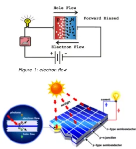
silicon in its pure state is an intrinsic semiconductor because at low temperatures its valence electrons are tightly constrained by bonds but when it gets in contact with energy such as heat or light, the bonds can be broken and the electrons are free to migrate through the lattice. shining light on the crystal produces broken bonds and then
the silicon becomes a conductor. the more bonds are broken, the greater its conductivity. an electron that has broken free wanders through the lattice and it leaves behind a broken bond, with a
[image:8.792.440.713.222.521.2]positive charge, known as a hole. When electrons jump into vacant spots, a hole moves through the crystal as a positive charge (see figure 1). If two contacts are attached and an external voltage is ap-plied by using a battery, current will flow due to free electrons will move one way through the holes. This mechanism is shown on figure 2 and is named the semiconductor p-n junction. (Paul a. lynn, 2010)
Figure 1: electron flow
1.1.2 Thin-film PV cells
In figure 3 the build-up of an amorphous silicon PV cell is showed. Making a thin-film cell starts by taking a superstrate or substrate, which is the name of the front- or backside of the module, which can be metal, glass or plastic. the next layer is a layer of amorphous silicon, copper indium diselenide (cis) or cadmium telluride (cdte), which is used as the semiconductor material. this semiconductor layer is deposited on the super- or substrate (s. roberts & n. guariento, 2009). The term “thin film” owes its name to this method of ‘deposit-ing’ the film. The layers are applied in strips in order to achieve the inter-cell connections.
Thin-film modules do not have a metal grid for the top electrical con-tact. instead, it uses a highly transparent conducting oxide, such as tin oxide. they conduct electricity very well. unless the transparent con-ducting oxide serves the function of antireflection, an antireflection coating is needed on the top of the conducting oxide layer. (www. daviddarling.info)
to provide mechanical strength and the electrical connections, the solar cells are encapsulated in a layer of ethyl vinyl acetate (eva). the top is covered by glass or plastic and to maximize light
transmission, it is sometimes treated with an antireflection coating made of silicon nitride or titanium oxide and this makes the appear-ance dark blue. Sometimes for aesthetic reasons the antireflection coating is left off so the cells will stay natural dark grey, although a disadvantage is that reflection losses increase from 3% to 30%. underneath the Pv cells a sheet of a synthetic polymer like tedlar is situated, to protect the cell from fluids and chemicals.
most Pv modules are provided with aluminum frames to support struc-ture and to simplify attachment to the roof. Only when reflections are undesired, modules without frames are preferred.
Thin-film technology is an aesthetically suitable cladding material. the modules cost less than crystalline silicon modules and standard thin-film modules are available in a variety of sizes. (S. Roberts & N. Guariento, 2009). Most of the commercial production of thin film
solar is cadmium telluride, with an efficiency of 11%. (Photon Inter-national, 2009).
ENEA developed a curved solar cell by depositing thin film amorphous silicon layers on circular slightly curved borosilicate glass. these glass substrates are on the market in sizes ranging from 40mm to 250mm. Then the cells are deposited on transparent plastics and finally the cells can be electrically connected in Pv modules.
a remark needs to be made. the technologies used need to have some improvement before it can be used. the thickness of the
amorphous silicon layer and its electrical conductivity reveal a strong disuniformity in thickness. this can be caused by the varying spacing between substrate and power electrode. so before the cells will be usable, an improvement of the thickness uniformity is necessary in order to realize this kind of Pv cells.
(scognamiglio, a. delli veneri, P. a.o., 2009)
2. Pv modules
2.1 connecting Pv cells in a module
in the previous part of this chapter the working of Pv cells was explained. in short, a Pv module is made by connecting Pv cells in a string and placing them in a frame.
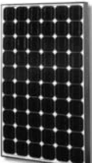
When talking about PV modules, most people firstly think about the standard square, flat, dark colored PV module, which is showed in figure 4. This exterior features have its origin in aerospace and was directly adopted from there. later, man started to pay attention to the aesthetics for the use on earth. nowadays, more and more inno-vative Pv products are introduced to the market. some of them are shown in chapter four.
the dimensions of Pv modules are various. they are available in the sizes of 0,25 square meter up to about five square meters. The thick-ness can vary from about one millimeter to about forty millimeters. of course the weight varies and depends on the size and thickness of the module. the modules are dark colored, mostly black, grey or blue. The cells in a thin-film PV module are connected by ribbon. This is a wire rolled from round copper that is burr-free. it is also been coated,
to ensure protection against corrosion or interaction with Pv module encapsulants (www.enlog.us).
2.2 generating current
a string of Pv cells is called an array. it is important to make arrays of cells that are able to generate the same amount of current, which is determined by the irradiance and tilt, because the resulting current will be determined by the minimum. this rule also counts for arrays into a module.
keeping the effect of connecting arrays with different current energy low, is a reason for designing modules that are not or only slightly curved. because when modules are curved, they will catch sunlight from different directions that decreases the total generation of electricity.
Further, it is important to keep zones sufficiently large, because the zones are divided in the amount of current they generate and
every different zone needs a separate inverter. in the next chapter, more information about inverters can be found. the second reason for keeping the module large, is that having a low number of connec-tions between the individual modules means decreasing the chance of mismatches.
Pv modules can be bought in different kind of voltages, for example 12, 16 or 20 v. the number of cells you need in a Pv module
depends on the kind of cells and how many there are connected in series. the current and voltage a cell produces, differs per sort of Pv cell. for example, a crystalline Pv cell produces 3W at 0.6v dc. so the current is (3/0.6) = 5a. to realize a higher power unit and a higher voltage, thirty or more Pv cells are connected in series and parallel and together they form a Pv module. in order to realize high
figure 5: formulas current and voltage
Formulas cells connected in series: Utotal = number of cells * Uone cell. And Itotal = Ione cell. Formulas cells parallel connected: Itotal = number of cells * Ione cell. And Utotal = Uone cell.
Formulas cells connected in series: Utotal = number of cells * Uone cell. And Itotal = Ione cell. Formulas cells parallel connected: Itotal = number of cells * Ione cell. And Utotal = Uone cell.
[image:10.792.161.255.379.545.2]table 1
high enough by connecting these strings parallel. for the formulas of cells connected in series and parallel, you are referred to figure 5. in the example of using crystalline cells, a Pv module of 6v, 4a can be made by putting (6v/0.6v=) 10 cells in series, and (4a/0,5a=) 8 cells parallel.
the voltage generated is direct current (dc) and can be used to charge a battery when putting it on its two output contacts. When us-ing a PV inverter (figure 7), the DC current can be converted to alter-nating current (ac) and then it can be used on the grid. the (nominal) power output of photovoltaics is usually described in kilowatt peaks (kWp). (Paul a. lynn, 2010)
this power rating is given by the manufacturer of the module or system. it is the power output of the module measured at 1000W/m2 solar irradiance, a module temperature of 25°c and a solar spec-trum corresponding to an air mass of 1.5, all tested under standard test conditions. (www.re.jrc.ec.europa.eu). if you want to calculate the voltage, the illumination, system losses, slope and azimuth, this is the horizontal angular distance from the northern point of the horizon, need to be taken into account.
2.3 aesthetic asPects
cells based on cis and cdte have a dark brown to black appear-ance because they are designed to reflect a minimum of light to pro-duce maximum electricity. other colors can be obtained by varying the thickness of the anti-reflection coating, and by treating the glass or plastic that supports the Pv module with certain techniques, differ-ent textures can be obtained. But of course the reflection will increase and efficiency will decrease by 15–30% depending on the color. cells which are custom made like this can be two or three times the price of normal cells. It is also possible to make flexible and curved thin film PV modules.
2.4 efficiency and Price
The efficiency of thin-film cells is lower than for crystalline silicon tech-nology and of course a lower efficiency means a larger area is re-quired to achieve the same power. but on the other hand, crystalline silicon is more expensive. (s. roberts & n. guariento, 2009)
over all it can be said that prices of Pv panels drop every month. in october 2010, the average price for monocrystalline and
polycrystalline silicon Pv was €3,2 per watt. the lowest price found in October for thin film modules is €1,0 per watt. Amorphous silicon is in generally 0,5 times the price of mono and polycrystalline silicon, so this will be 1,6. the price of inverters measured in october €0,5 per watt. these prices are exclusive of sale taxes. When purchasing a whole Pv system also the inverter and install costs need to be considered. in general it can be assumed that a Pv system is 1,5 times the cost of the Pv panels (www.solarbuzz.com). in table 1 an
overview of different types of solar cells and the corresponding efficiency, area requirement and price per watt is shown.
The reason why thin film solar modules have not replaced older types yet is because they are not as efficient as you can see in table 1. On the other side, their thinner structure needs less material, and this allows much cheaper modules to be produced. Thin film modules are as high as other technologies in terms of price per watt (www. solarpowerfast.com). Biggest reason why thin film cells will be used in this project is their flexibility and therefore their possibility to apply in a wide variety of applications (ezinearticles.com). since we are talking about spherical (bubble) shaped solar cells, the flexibility is a requisite.
Type Typical module
efficiency Area requirement Price in October 2010
monocrystalline silicon 12–15% 7–9 m2/kWp €3,2 per watt
multicrystalline silicon 11–14% 7–10 m2/kWp €3,2 per watt
thin-film CIS 9–11% 9–11 m2/kWp €1,0 per watt
thin-film CdTe 6–8% 12–17 m2/kWp €1,0 per watt
amorphous silicon 5–7% 14–20 m2/kWp ≈ €0,5 per watt
3. Pv systems
3.1 connecting Pv modules
Only one PV module does not generate enough current to make profit of solar energy. therefore more Pv modules need to be connected in a photovoltaic system. this can be used to generate and supply elec-tricity for private or commercial purposes. a Pv installation includes an array of Pv modules, an inverter, interconnected wiring and batteries or a connection to the grid.
the formulas for calculating the current and voltage of the Pv sys-tem are the same as the formulas used to calculate these electrical features in Pv modules. Pv modules can also be placed in series and parallel at the same time. When, for example, two 12v/4a panels are placed in series and two parallel, the voltage will be two times 12, which is 24v and the current will be two times 4a, which is 8a (figure 6).
figure 6: two 12v/4a panels in series and two in parallel. this doubles the current and voltage to 24v and 8a.
3.2 inverter
to convert the current that is produced by a number of panels to a higher voltage an inverter is needed, which converts dc to ac. mostly, several modules share the same inverter because they are more efficient and cost effective at higher voltage.
inverters are available in several colors and sizes. mostly they are square and the size and price depends on the power that has to be converted (see figure 7). This can vary between 1 kW, with a size of 200*400*400 mm and 20 kW, with a size of 700*500*250 mm. it is important to connect modules with the same current, caused by irradiance and tilt of the module to one series string. this is because the resulting current will be determined by the minimum, so this being from the modules receiving least irradiance. When zoning a Pv array, zones should be kept sufficiently large so that zones of an equal area will generate a high voltage. the other advantage is that there is only one size of inverter in use, which helps with maintenance and replacement.
3.3 levels of integration
three levels of products to integrate photovoltaics can be distin-guished: not integrated, partially integrated and totally integrated Pv modules. these levels are being explained and an example will be showed.
3.3.1 not integrated Pv modules
On the first level you can find PV modules designed to be used on any building (figure 8). A particular mounting system is needed. Not integrated Pv modules are also called added-on photovoltaics. this means that Pv modules are constructed on a building using a metal structure and the only function is to generate energy.
3.3.2 Partially integrated Pv modules
[image:13.792.503.656.205.430.2]Partially integrated Pv modules are designed to be used on a partic-ular part of the building (figure 9). The mounting system is designed for the particular module. but the modules are not substituting the surfaces where the Pv is added on. examples are: shading devices, Pv modules on green houses, terraces or roofs, facades, balustrades or modules on urban furniture elements and acoustic barriers. for this project Pv modules are designed to be used on roofs and facades, but the modules are not substituting them. for this reason the module to be made can be placed in this category.
[image:13.792.176.264.258.417.2]figure 8: lumos ls250 black frame
3.3.3 totally integrated Pv modules
this is also called building-integrated photovoltaics (biPv). these are PV modules that substitute the traditional building components (figure 10). in other words, the Pv modules are not only used for producing electricity, it also takes on the role of a building element. this Pv sys-tem is designed to be directly integrated in the building. the mount-ing system is also totally integrated. biPv has a low market penetra-tion. In Germany in 2004 only 1% of the energy generated by PV came from biPv. (s. roberts & n. guariento, 2009)
figure 10: Pv cladding on a building
3.4 Positioning of Pv module
external aspects that need to be taken into account are insolation and spectral distribution of sunlight. insolation is shared very unequally, because of the spherical shape of the earth and because of clouds. it is possible to calculate the average insolation at a particular location. then the next important thing is to consider the sun’s spectral distribu-tion, because different types of solar cells respond differently to the various wavelengths in sunlight. indirect solar radiation also needs to be taken into account, one is the diffuse component because of light scattered by clouds and dust particles in the atmosphere. (Paul a. lynn, 2010)
the satellite application facility on climate monitoring (cm saf) has an online application in which it is possible to calculate the perfor-mance of grid connected Pv in a certain point in europe with a cer-tain kind of Pv cells. using this website, a comparison will be made between different PV cells: crystalline silicon and thin film CIS and different places in europe: Portici and enschede.
Filled in on re.jrc.ec.europa.eu (See fig. 11):
- radiation database: climate-saf Pvgis, because this is the newest database version, and it includes a choice of solar radiation databases for some regions.
- Portici, italy and after that enschede, the netherlands is pointed on the map
- Pv technologies are crystalline silicon and after that cis, because it is the thin-film module type with the highest efficiency.
- installed peak Pv power: 1,0 kWp. - Estimate system losses: 14%
output is a table (table 2) and a graph that shows the average monthly electricity production from the given system in kWh and the average daily sum of global irradiation per square meter received by the modules of the given system in kWh/m2.
the average monthly production and consequently the total production for a year is only a little bit higher for crystalline silicon than for cis, due to the estimated losses. the loss due to temperature, using local ambi-ent temperature, is 12.4% for crystalline silicon and 10.3% for CIS. Because this difference between crys-talline silicon and cis cannot be seen in a graph, below a graph (figure 12) of the monthly production in kWh through the year in Portici and enschede is shown.
[image:15.792.33.463.108.552.2]in sum, building integrated cis 1,0 kWp modules with an optimal slope and azimuth and a 14% system loss in Portici has the highest average yearly electricity production, which is 1440 kWp a year. in the nether-lands, that is 896 kWp, which 62% of the production in Portici.
[image:15.792.477.754.348.547.2]figure 11: calculation insulation
3.5 refunding
When connecting the Pv system to the grid, it is possible to export electricity when building demand is low. in case of high demand and using all Pv output, electricity of the grid can be added. switching between building use and export happens automatically. (s. roberts & n. guariento, 2009)
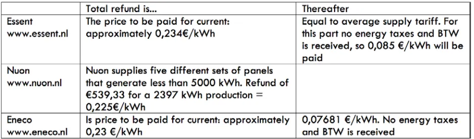
in a lot of countries overproduction of solar energy can be supplied to the grid in exchange for compensation. in the netherlands it is of-ficially stated in the Energy Law. From 2010 the rule is that the supply of solar energy is refunded up to a 5000 kWh production per year for the price of current of the moment. When supplying more than 5000 kWh/year, the compensation differs per energy supplier. but solar systems are not profitable in the Netherlands; it is a matter of breaking even. in the next table (table 3) the regulations for the three biggest energy suppliers in the netherlands are shown.
it can be concluded that the average proceeds amounts
[image:16.792.163.632.396.534.2]0,23€/kWh*5000 = €1150. if more energy than 5000 kWh is gen-erated, the profits are very low.
3.6 iec requirements for Pv modules
the international electrotechnical commission (iec) is an international organization for standardization of all national electrotechnical com-mittees. in iec 61730-1 the fundamental construction requirements for photovoltaic modules are described in great detail. below an overview of relevant standards for my project are shown.
construction
a module that comes from the factory shall be completely assembled or it shall be provided in subassemblies. an assembly part needs not to be affixed to the module at the factory.
ground continuity should not be interrupted by installation of the module.
if loosening, turning or moving of parts could result in a risk of injury to persons, parts should be prevented from that. While preventing a part of turning or loosening, friction between surfaces is not accept-able.
mechanical securement
a connection shall provide electrical contact without strain on con-nections and terminals. concon-nections will also be mechanically secure which means they are held by encapsulation systems.
an uninsulated live part will be prevented from turning or shifting in position, by securing it to its supporting surface.
connections
a module shall lead to accommodate current-carrying conductors of the load circuit.
field connections shall be located that they will not be exposed to direct sunlight or it will be rated for exposure to direct sunlight and its degrading effects.
a connector for the output circuit shall have the right voltage and current. the connector shall be assumed to be suitable for assembly only. a material that is water and uv resistant shall enclose a
connec-tor that will be exposure to the outdoor environment. a module with accessible conductive parts that form a frame or mounting system or with a conductive surface area greater than 10 cm2 shall have
provi-sion for grounding.
material
any material or combination of materials should be provided against deterioration or corrosion.
all polymeric materials shall have a thermal index of at least 90°c. in addition, the minimum relative thermal index shall be at least 20°c above the maximum measured operating temperature.
Polymeric materials that will be used as the outer enclosure for a module shall have a maximum flame spread index of 100. The poly-mer shall be evaluated for ultraviolet radiation resistance.
3.7 iea requirements for Pv modules
the international energy agency (iea) was concerned with photovol-taics integrated in buildings within task 7 “Photovoltaic Power
systems in the built environment”, task 10 “urban-scale Photovoltaic applications” and task 41 “solar energy and architecture”. the criteria for designing with high architectural quality when applying BIPV architects are defined in Task 7 of the photovoltaic Power systems Program of the iea. although a module has to be designed which is suitable to add on the building and not to integrate in the building, these are also good guidelines for this project.
1. naturally integrated: the Pv system completes the building. 2. architecturally pleasing: the Pv system adds eye-catching
features to the design.
3. good composition: color and texture of the building should be in harmony with the other materials. Often, also a specific design of the Pv system can be aimed at (e.g. frameless vs. framed modules).
4. grid, harmony and composition: the sizing of the Pv system matches the sizing and grid of the building.
5. contextually: the total image of a building should be in harmony with the Pv system.
6. Well-engineered: this concerns the question if design details are well conceived.
7. innovative new design: architects should think innovative and creative to enhance the Pv market and add value to buildings.
(schoen, t, Prasad, d e.o., task 7 of the iea Pv power systems pro-gram – Achievements and outlook, 2001)
3.8 building regulations
3.8.1 the netherlands
the ministry of housing, spatial Planning and the environment (in dutch: ministerie van volkshuisvesting, ruimtelijke ordening en milieu) formulates regulations concerning space, living, environment and gov-ernment buildings. if the six requirements concerning solar modules below are met, a building permit is not necessary:
1. the solar module must be situated on the building.
2. the solar module is intended to provide in energy supply of the building itself. it is also permitted to place the module on or at the building in order to supply another building on the land.
3. the module has to be integrated with the electrical store instal-lation. if that is not the case, the installation has to be placed in the building in question.
4. in case the module will be placed on a pitched roof, then it must not stick out the roof, must be placed directly on the roof and the angle of inclination of the module must be the same as the pitch of the roof. 5. In case the solar module will be placed on a flat roof, it must be placed at least as far from the roof as the height of the roof and the inclination of the module cannot be over 35°.
6. the module can’t be placed at a monument or building which is marked as protected by the state. (vrom, 2003)
the ministry of finance (in dutch: ministerie van financiële zaken) supports the so called sde (in dutch: stimulering duurzame energie-productie) which stimulates projects concerning durable energy which do not return enough money. sde covers the shortage if man
applies for a subsidy.
3.8.2 italy
In Italy there are no specific building regulations concerning PV in or at buildings at this moment. there are only requirements to be met if you want to be qualified for getting subsidy in the form of a feed-in tariff. this is a policy mechanism designed to encourage the use of renewable energy resources and to help accelerate the move toward grid parity. With grid parity the point at which alternative means of generating electricity is equal or cheaper in cost than grid power is meant.
two different tariffs are established depending on the level of in-tegration of Pv. the higher the level of architectural inin-tegration, the higher the tariff will be.
the ministerial decree introduced the reward rate for architectur-ally integrated Pv systems on the 19th of february 2007 in the so called “Guida agli interventi validi ai fini del riconoscimento dell integrazione architettonica del fotovoltaico” (in english: recognition of architectural integration PV-guide). In this you can find guidelines concerning the distinction between totally or partial integrated Pv. in the case of partial integration, three typologies are taken into account and in the case of architecturally integration, ten typologies are taken into account.
the decree is valid until december 2010. starting from January 2011, until the end of 2013, the ministerial decree will substitute the previous regulations. the main change is that there is no longer a distinction based on the level of integration, but only four categories of Pv systems are admitted to be funded. one is “building integrated Pv with innovative features”. since the guide has not yet been pub-lished, we still do not know the exact definitions of the categories.
in the guide totally integrated Pv is described in the following sub-divisions:
1. Pv integrated in the building skin (cladding) 2. Pv integrated in pensiline, pergola or tettoia:
- Pensiline: structure ancillary covers placed parking or pedestrian walkways.
- Pergole: the relevant units in nature residential, to allow the support of green vine on terraces courtyards or gardens, with a reduced area of coverage in the plant
- Pv tettoia: is a structure that covers outside buildings, consisting of pitched resting on the wall of the buildings themselves.
these three kinds of modules must have a minimum ground clearance of two meters.
3. Pv as transparent surfaces of buildings
4. Pv used as acoustic barriers on side of the road 5. Pv integrated in lighting elements and public facilities 6. Pv sun-shading systems
7. Pv integrated in balustrades and parapets 8. Pv integrated in windows
4. Products
in this chapter a small market research is done. innovative products that are suitable for blob-buildings are listed and explained. the pros and cons of every product are also given. these arguments are concluded by drawing the modules on several buildings (see appen-dix i).
4.1 flexible thin film module
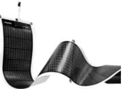
Thin-film solar photovoltaic technology offers the benefits of low-cost in exchange for high efficiency. The lightweight and flexible tech-nology can easily be put on for example the facades, roofs or rain screens of a building (figure 13). For this building the surface area should not be an issue, because for an optimal generation of energy a large area is required. (www.pv-tech.org)
Pros and cons
The biggest advantage is that the module is flexible so it fits on curved surfaces. it is a disadvantage that the modules cannot be placed on small surfaces because in this case the energy generation will be too low.
4.2 sPhelar
the most important sphelar product is the module that is half spheri-cal-shaped (figure 14). The solar cells are placed on the inside of the envelope of the sphere. that is why they can produce electricity from any incoming light, including light that is already bounced off other surfaces, giving an efficiency rating of around 20%, so it has a com-petitive position in comparison with high-end traditional solar cells. it provides in small and compact Pv modules and can be used for low power applications and they can be connected either in parallel or in series. it is available in sizes from 38.1 x 24.1mm until 155 x 52mm. the maximum power varies between 45mW and 940mW.
sphelar also has modules in an array of 12 cells, in a cylinder shape and a spherical micro solar cell mounted in a plastic case. (www.kyo-semi.com)
Pros and cons
the biggest advantage is that the sphelar is small-sized. no matter how sharp the curves of the building envelope are, the underside of one of the sphelar will fit on every envelope.
[image:20.792.486.656.270.408.2]the building envelope can almost be covered by the sphelars, be-cause of the availability of bigger and small ones, but little pieces of the skin will be uncovered. a disadvantage can be that because of their height, they will be placed in each others’ shadow, on some hours of the day. because of their typical shape it is insuperable to
[image:20.792.116.330.294.447.2]Figure 13: a flexible thin film module
4.3 etfe
This technology is based on extremely flexible, amorphous thin-film Pv cells embedded in etfe laminates. it has a total thickness of 1µm (fiure 15). They can be cut to length and be aligned to meet every specific requirements of any project, up to three meters because of the laminating equipment. this process of lamination ensures that the photovoltaic cells are effectively protected against loads and stress-es, as well as against uv, moisture and weathering.
the surface is resistant to soiling. Pv flexibles can be used for roofs and facades without an additional supporting structure. it is also used in the outer layer of pneumatically supported cushions. the Pv cells are not only generating current, they also provide shade.
Pros and cons
etfe is an appropriate product to replace roofs and facades be-cause it is possible to resist uv, moisture and weathering. a disad-vantage is that it is only available up to three meters so a supporting system is needed in case you wish to cover a bigger surface. because of the pneumatic cushions, curved shapes can be achieved, but with this technology a double curved, s-shape cannot be reached without a supporting system in between.
4.4 solyndra
Solyndra (figure 16) is the name for the long cylindrical shaped pan-el. each panel is made up of individual modules, which are all placed horizontally. one module contents 150 individual solar cells. the pan-els are able to capture sunlight from a 360-degrees angle, so be-sides direct sunlight also diffuse and reflected sunlight will be added to the energy production. for this a white roof surface is necessary. the system is light weighted and no mounting system is needed. (www.solyndra.com)
Pros and cons
[image:21.792.478.681.197.439.2]an advantage is that the shape allows placing the panels on building surfaces which are curved one-sided, but two-sided curved surfaces cannot be covered with solyndra. another big advantage of this sys-tem is the higher efficiency rate because the cells are facing 360-de-grees. Because of the striking shape it is insuperable to influence the character of the building.
[image:21.792.88.339.246.408.2]figure 15: etfe
5. defining the requirements
In this chapter the requirements are defined. This will be done by us-ing the information that was already gathered about Pv cells, mod-ules and systems and gathering new information about the wishes of architects, materials and blob buildings. this chapter starts with a summary of a survey held in the past. then a new survey is shown. next, a material selection will be done, blob buildings will be ana-lyzed and this chapter will end with a list of requirements.
5.1 iea survey
the international energy agency (iea) task 41 has dealt with this issue of wishes of architects for new Pv modules. members of this taskforce held a survey concerning the integration of solar energy systems and architecture in order to identify barriers that architects are facing concerning integrating Pv technologies in their design. The international IEA Task 41 group defined eighteen barriers and seven strategies of solar system utilization and the respondents were asked to vote for the issues they consider as most important.
the survey was about photovoltaic systems and solar thermal systems but for this assignment only information about photovoltaic systems is useful. the differences in outcome between countries is not important in this case, so the average outcome will be used.
the survey was sent out to architects in thirteen countries (most of them in europe, the rest in canada and south korea). through the survey the barriers and possible strategies of integrating solar energy in ar-chitecture and the needs of the architects considering solar energy in architecture are investigated. below the main conclusions of the 255 responses are listed.
barriers
• Economic issues were found to be the most important barrier
(21%), especially the high product price. Clients are mainly interesed in the paid back time and therefore interested in the investment costs. but, solar components can replace other building components by their integration into the building envelope, consequently they fulfil mul-tiple functions and relative costs become lower.
• The lack of knowledge of architects is considered as second most important barrier (19%). There is resistance because solar sys-tems are not considered to be building components, but technical de-vices. clients and developers should have a basic knowledge of solar energy systems to understand the benefits of their investment.
• Third most important barrier is the lack of oriented literature on the technologies and useful and understandable data for archi-tects about solar energy (18%). A solution to take away this barrier is to make architecturally oriented information about solar energy available, in the form of for example handbooks or websites.
strategies
• Regarding the strategies, Economical strategies are consi-dered to be the best (42%). Participants of the survey think govern-mental incentives can be an important support. two systems used are subsidies for the initial investments and feed-in-tariff systems. the second one means that overproduction of electricity is bought by the electricity distributor.
• Second most important strategy is process (23%). Not enough simplified computer solar tools are available for architects. There are many tools for solar design. free or subsidized technical support from professional associations for the early design stage would encourage the use of solar products in architecture.
general
of interest by clients and developers has his origin in the fact that so-lar modules are considered to be technical devices rather than build-ing components, mostly due to the lack of knowledge about techno-logy and available products. therefore architects and even more clients often resist using them in their design.
it should be remarked that the barrier “products” is considered as being the last most important barrier (11%). A variety of products have been developed for building integration but still aesthetical is-sues are not the focus of product development. there is a need for complementary building components like for example dummy ele-ments. (farkas, k, munari Probst, m.c., horvat, m., 2001)
5.2 Personal survey
in order to create a concept for the bubble Pv modules that are likely to be used in the future, the wishes of architects should be taken into account. as mentioned before, the international energy agency has dealt with the issue of general barriers that architects are facing con-cerning integrating Pv technologies in their design. outcome of the survey was that economic issues were the largest barriers.
in this phase it is necessary to go more into detail to be able to de-velop a product that enables architects to integrate Pv in architecture more easily. consequently, a survey is sent out in which architects were asked to fill in questions about barriers, wishes and solutions concerning Pv products to be used in architecture and in architecture with curved envelopes.
The survey can be found in Appendix II and is held among five archi-tects. the data is various because the nationalities, backgrounds and experience of the architects differ from person to person. the archi-tects interviewed execute their profession in italy, the netherlands, norway and Japan.
one of them has not worked with Pv modules, three architects worked with Pv modules in one or two projects and one very experienced ar-chitects worked on a hundred Pv projects. a summary of the usable
outcomes is listed below.
barriers
The architects were asked to consider the importance of five possible barriers for integrating Pv modules in architecture by using a 1-5 scale.
the largest barrier appears to be the shape of Pv modules with an average grade of 3,8.
the general lack of products is rated to be the second largest barrier (grade: 3,0) and the third largest barriers are color and material of the modules and price of the modules with both an average grade of 2,8. harmony with the environment is considered to be the least important barrier (grade: 2,2).
a note needs to be placed. according to the opinion of mr. mar-tocchia, Pv elements need to be treated as a technical installation and not as if they are architectural elements. therefore he graded all barriers as 1. there is one other problem mentioned: not being updated. to the opinion of mr. røstvik another barrier is the lack of knowledge about the properties of and possibilities with Pv modules. the reason that is mentioned mostly for not using Pv is the price for building integrated design. clients avoid additional investments and affordable modules integrated in a facade are usually are aestheti-cally unattractive.
customizability
according to the opinion of the architects the most important custom-ization of Pv modules should be the shape. color, positioning of cells and integration of led’s follow on second place. other possibilities mentioned are transparent Pv modules and attractive roof tiles in a traditional shape.
curved envelopes
other hand, noted that for small Pv modules the chance of electric and material connection failure increases due to the number of con-nections you will need when using a lot of small Pv modules. regard-ing to thin film modules he mentioned that the efficiency per m2 is too
low to even cover only a small part of the energy consumption of a building.
largest barriers for standard module in curved architecture are price and lack of products.
conclusions regarding the Pv module to be made
some interesting conclusions can be made, which can be translated in the following requirements for the Pv module to be made:
- The shape of the module must fit on the shape of the curved archi-tecture.
- the price of the Pv modules to be integrated must not be too high. - it is important that the kind of material and color of the module can easily be integrated with the building.
- the shape of all the modules together on a building needs to be customizable.
- customizable properties like color, positioning of cells and integra-tion of led’s are opintegra-tional.
- the number of electrical and material connections needs to be kept low in order to increase the change of connection failure.
5.3 material selection
5.3.1 fire safety
When constructing a building, regulations for fire safety should be considered. in the dutch law it is said in short that materials may not be easy flammable and may not spread fire easily. Practically this means that in case of fire the material should not take fire quickly and when it is in fire, it should not spread through the material quickly. A material that slows down the fire is preferred in a lot of cases
(overheid.nl). to determine how safe a part of the building needs to be, firstly the category in which the material of the construction parts is used needs to be determined. categories are for example the function of the room, the kind of building, the size of the room and the locations (totally inside or partly outside). secondly, nen (stichting nederlands normalisatie-instituut) divided the materials contribution to fire in four classes, from low (class 1) to strong (class 4) contribution to fire spread. This also depends on the flammability of the material. (www.nordictimber.nl). it can be found that parts that are usually integrated in walls, such as a door, window or window frame is placed in class 4, which means that these parts of the house are allowed to contribute strongly to the spread of fire. When one of the sides of the construction parts is positioned in the direction of a street, the corresponding class is 1, which means that contribution to fire spread should be low. but this does not hold for the top a roof (wetten.over-heid.nl). If the material is easy flammable or spreads fire easily, it could be treated with a fire-resistant coating. This is a thin film material that can be used to cover the material, in order to make it resistible to fire.
table 4: iec requirements in ces figure 17: materials in ces
5.3.2 material selection in ces
To select a proper material for the outside of the thin-film PV module cambridge engineering selector (ces) is used. the iec requirements are translated in the next requirements to be filled in in CES (table 4):
- all materials are participating in this selection process. - all polymeric materials shall have a thermal index of at least 90°c. in ces the maximum service temperature can be defined, so this will be done on 90°C.
- Polymeric materials that will be used as the outer enclosure for a module shall have a maximum flame spread index of 100. flame spread index is in short a comparative measure of the ability of the material to resist flaming combustion over its surface (www.answers.com). but this aspect cannot be found in CES. Therefore flammability will be taken into account, which is represented in ces. flammability is ranked on a four-point scale, because most polymers are inherently flammable, although to differing degrees.
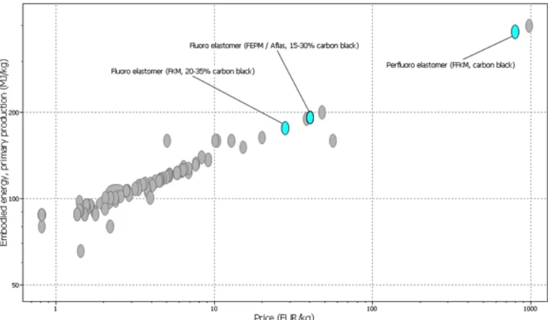
- because price and embodied energy are the only quanti-tative properties, these two will be put on the x- and y-axis.
the result of these requirements are shown in the graph you can see on the right.
When using this approach there are only three materials left which meet all the requirements (see figure 17). Unfor-tunately those materials are quite expensive. the costs of fluoro elastomer (fkm) is about 29 €/kg. for fluor elas-tomer (FEPM) this is 42 €/kg and Perfluoro elaselas-tomer costs about 831 €/kg. to compare: the average price of glass is about 5 €/kg.
so a different approach is tried. it is found that the
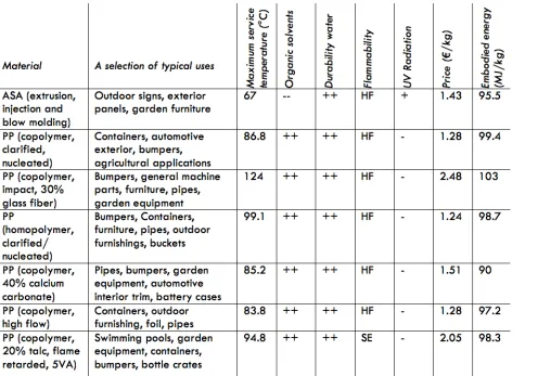
the second strategy is to look for materials in products that are used outside, because from these products, we know they should be at least resistant against organic solvents and water. a list of suitable materials is selected (table 5) and the corresponding properties for products like outdoor furnishing, containers and bumpers.
as said in the chapter before this one, the Pv modules are allowed to contribute strongly to the fire spread. So the material where the mod-ule is made of may have the property of being highly flammable. The maximum service temperature was set on 90°c. uv resistance is no hard requirement because an uv resistant coating can be used.
These facts put forward “PP (homopolymer, clarified/ nucleated)” as the best material, because it meets the requirements and has one of the lowest embodied energy and the lowest price. to compare: the average embodied energy from glass is about 27 mJ/kg and for aluminum it is 200 mJ/kg. PP is not resistant to uv radiance so there has to be treated with an uv resistant material.
[image:26.792.48.544.214.561.2]PP can be molded and this is the perfect production method for the parts that are needed in the module. one of the tradenames of this material is Polybatch and this is available in several kinds of colors. (see figure 18).
[image:26.792.561.722.257.432.2]guggenheim museum
selfridges building
rabin center
Water Pavilion
kunsthaus
fluid vehicle bus station
international convention center 1
2
3
4
5
6
7 5.4 analysis of blob buildings
Before starting the Blob analysis, it is required to first define the term “blob”. in literature, people are having different views on the term. below the explanation that is found most of the times is been sum-marized.
blob is an abbreviation for the words binary large object. this is a collection of binary data in a data management system. computer-aided-design software is needed to define the shape.
in the architectural context blob is a movement in which buildings have organic shapes. in blob buildings there are various curves, different slopes and sharp angles. the walls and roof are double-curved and mostly the walls follow the floors in a smooth way.
in this sub-chapter an analysis is made of seven very different blob buildings. the dimensions of the total building, of the seperate parts of the building, curvations, the radii, the use of materials and the presence of bubbles are considered. because of the variety in shape and dimensions, these buildings can be seen as a representation of all blob architecture.
1 guggenheim museum
abando, bilbao, spain
frank gehry, 1997
the guggenheim museum bilbao is a museum of modern and contemporary art. large-scale art is placed in the biggest room of the museum, which is 30 by 130 meters. on this picture you can see about 160 meters length of the building.
dimensions total building • total length: 220m by 130m • height: 50m
• smallest radius of surfaces where Pv modules can be placed on: 5m, biggest radius: 100m
dimensions sePerate Parts
• average dimensions of the seperate parts of the buiding: 20x40m.
• average dimensions of the maximum simple geometric parts: 0,5x0,5m.
considerations
• Parts are curved one-sided. seperate parts are placed in all different directions, so surfaces are facing all quarters of the compass.
• bubbles can be found on architectural scale.
• facades and roofs does not merge into one another.
2 selfridges building
contemporist.com/2007/11/24/the-selfridges-building-in-birmingham/ http://www.danda.be/reviews/selfridges_birmingham_future_systems/
birmingham, england
future systems architects, 2003
the birmingham store consists of three walls. it is blue and is clad with around 15000 spun aluminium discs, each 0,6m in diam-eter. The fluid form strikes a contrast with conventional buildings nearby, but it is a bit alike gothic architecture. the selfridges building is curved three-dimensionally. its design makes no dis-tinction between ‘walls’ or ‘roof’, and there are no abrupt angles to break the organic, flowing lines.
dimensions total building dimensions: 100x110m. length bridge: 37m.
smallest radius: 8m. biggest radius: 40m. dimensions sePerate Parts
• average dimensions of the maximum simple geometric parts: 0,6x0,6m, which are the dimensions of the discs.
considerations
• Parts are curved three-dimensionally.
• seperate parts are facing all quarters of the compass. • bubbles can be found both on architectural scale and as a
structural element on the envelope, because of all the alu-minium discs placed on the building.
3 rabin center
tel aviv, israël
moshe safdie, 2009
the building is made of giant surfboards of foam with stressed skins on both sides. The roof is subdivided into five different roof wings, two on one side and three on the other. in between a square building can be seen. under the roof a wall of glass can be found.
dimensions
• the biggest roof wing is about 30x30m. the minimum length dimensions of one of the wings is about 30x15m.
• maximum radius: 20m, minimum radius: 10m. dimensions sePerate Parts
• average dimensions seperate parts: 15-20m.
• average dimension of maximum single geometric parts: 0,5x0,5m.
considerations
• Parts are curved three-dimensionally.
• the roofs are placed in all different directions, so surfaces are facing all quarters of the compass.
• bubbles can be found only on architectural scale. • there is a clear distingtion between facades and roof. • use of material is heterogenous, but the surface of the roof
4 Water Pavilion
joostdevree.nl
oosterschelde, the netherlands
nox/ lars spuybroek, 1997
the Water Pavilion is made up of a fresh water pavilion which is 60m long and a salt water pavilion which is 40m. in both of the buildings complex two-sided curves are used. the buildings surface exists of thin stainless steel.
dimensions total building
• the three-dimensional curved building made of stainless steel is 60 meters long.
• the height is 12 meters
• this building is made up of 20 vertical parts of each 2m. • the maximum radius is 3m, minimum radius is 6m.
dimensions sePerate Parts
• the average dimension of maximum single geometric parts is about 0,25x0,25m.
considerations
• Parts are curved three-dimensionally. • there are no windows in the building
• the roofs are placed in all different directions, so surfaces are facing all quarters of the compass.
5 kunsthaus
graz, austria
Peter cook and colin fournier, 2003
the museum which is called “friendly alien” was built as part of the european capital of culture celebrations in 2003. contem-porary art of the last four decades are exhibitioned. the form and material of the gigantic buliding, stands out consciously against the surrounding baroque roof landscape.
dimensions total building
• the total surface of the building is approximately 7200m2.
sloped and special shaped roof is 4050m2.
• the dimensions spherical shaped parts is approximately 100x50m.
• the smallest radius of surfaces where Pv modules can be placed on is 15 m. maximum radius: 40 m.
dimensions sePerate Parts
• the average dimension of maximum single geometric parts is about 1x1m for the big part, for the small parts on top of the building, this is 0,1x0,1m.
considerations
• both the big part and the small parts where the building is made up of, are curved three-dimensionally.
• bubbels can be found on architectural scale.
• during the evening/night “balls” of light can be seen on the envelope of the building so bubbles can also be found as a 2-dimensional pattern.
6 fluid vehicle bus station
heingartner.com/?p=36 http://architettura.supereva.com/architetture/20030403/
hoofddorp, the netherlands
maurice nio, 2003
This bus station is has a so called fluid shape and so is totally three-dimensional. it is completely made of polystyrene foam and polyester and when it was made, it was the world’s largest structure in synthetic materials (50x10x5m)
dimensions total building
• the roof is very small, but long. the roof of the building is about 150 square meters.
• the building is made of seperate parts of about 0,5x0,5m. • smallest radius of surfaces where Pv modules can be placed
on is 2m. the maximum radius is: 100m. dimensions sePerate Parts
• the average dimensions of the maximum single geome-tric parts where the building is made up of are about 0,01x0,01m.
considerations
• there are no windows in the building and the total building is made of the same material. so use of materials is homo-geneous.
• it is curved three-dimensionally. facades and roofs are merging into one another smoothly, there is no floor.
7 international convention center
www.inhabitat.com/2009/01/26/ciccm-by-mansilla-and-tunon-architecture/
madrid, spain
mansilla + tunon architects in collaboration with matilde Peralt
the building is scheduled to be completed in 2012. it is cylin-drical shaped. it will house an rainwater catchment system. ap-proximately 21000 hexagonal solar modules will be placed on the surface. the building will contain an auditorium, event halls and exposition halls.
dimensions total building
• the dimensions are 110x40x125m.
• the building is made of seperate parts of about 0,5x0,5m. • the maximum radius is 50m and the minimum radius 5m. dimensions sePerate Parts
• the building is clad with 21000 solar modules, so it can be said that the building can be split up in these single geom-eterical (hexagonal) parts of 0,75x0,75m.
considerations
• there are no windows in the building. the building surface looks like it is made of the same material so the use of mate-rial appears to be homogeneous.
• it is curved three-dimensionally. the facades and roof merge into one another smoothly.
• bubbels can be found both on architectural scale and as a structural element on the envelope in 3-d. this one can be found in two ways: the hexagonal solar panels, and the bubbles which go into the right side of the building.
5.5 conclusions blob analysis
two important conclusions can be made of the research to blob ar-chitecture. one is about the biggest single geometrical part where the buildings can be divided in and one is about the smallest radii that can be found in the buildings.
the minimum dimensions of the maximum single geometric parts where the building is made up of is 0,25*0,25 meter in the Water Pavilion. the average maximum dimensions of all blob buildings together are 0,53*0,53 meter. there must be said that this are the dimensions of the surface of the building which are suitable for Pv modules to be placed, so very small protrusions and separate parts of the building are not taken into account.
the smallest radius that can be found in the buildings was 2 meters in the fluid vehicle station. In this case again dimensions of very small protrusions and separate parts of the building are not taken into account. the average smallest radius of all buildings together is 7,3 meters.
based on this information, it can be said that the maximum dimen-sions of a totally flat module applied on an average Blob building, should be approximately 0,5*0,5 meter.
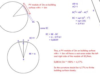
if a larger module is preferred, consequently a slightly curved mod-ule should be used to fit closely onto the building envelope. If, for example a module of 2*2 meters is chosen, and the building has a radius of 6 meters, the module should be curved about 4% (see figure 19).
In the calculation in figure 10 a minimum radius of 6 meters is chosen, because in this way most of the buildings are taken into account. in the guggenheim museum there are only some parts with a radius of 5 meters. the fluid vehicle bus station and the international convention center only have a smaller radius on the edges. so these buildings can be considered as if they belong to the group of buildings with a minimum radius of 6 meters. only the water pavilion is not consid-ered in the calculation because the minimum radius of 2 meters is too deviating.
in the calculation a module of 2*2 meters is chosen, because four of the buildings already have a front facade that is over 30*100 me-ters. this means that, if square Pv modules would cover these front parts of the buildings, 750 of them are needed. to keep the number of electrical connections tolerably low, the minimum dimensions of the Pv should be 2*2 meters.
F
EC
A
PV module of 2m on building surface with r = 6m
C
EC=? E
A F
BE = 6 B 1 B C A 6 AB=6 AC=1
BC2= AB2 - AC2
BC = sqrt (62 - 12)
= sqrt (35) = 5.9161
EC = BE - BC = 6 - 5.9161 = 0,0839 same EC
Thus, a PV module of 2m on building surface with r = 6m will have a rest-area under the left and right side of the module of 83,9mm. 0,0834/2m * 100% = 4,17%
[image:35.792.395.746.51.313.2]So the curvature should be 4,17% to fit the building surface closely.