The computational study in the unloading slot of the control
valve
LukášMrózek1,2*, LadislavTajč2, Jan Vimmr3, OndřejBublík4, VáclavSláma1 and Robert Kalista1,2 1Doosan Skoda Power, Experimental Research of Flow, Tylova 1/57, Pilsen, Czech Republic
2University of West Bohemia, Department of Power System Engineering, Univerzitni 8, Pilsen, 306 14, Czech Republic 3University of West Bohemia, Department of Mechanics, Univerzitni 8, Pilsen, 306 14, Czech Republic
4University of West Bohemia, NTIS – New Technologies for the Information Society, Univerzitni 8, Pilsen, 306 14, Czech Republic
Abstract. The flow in the unloading system of the control valve is modelled using the numerical simulation. The proportional flow values for various widths of the slot and openings are evaluated. The changes of the pressure and Mach number in the space of the valve are recorded for the selected pressure ratios. The influence of the length of the slot on the mass flow changes is assessed. The results are compared with the experimental findings.
1 Introduction
Control valves enable supply to the steam turbine with such a quantity of steam which is necessary to achieve the required performance. Their dimensions are chosen with respect to the admission pressure of the steam and the steam flow rate. The principle of the regulation is based on the change of the flow area using the controlled lift of the valve cone. Abilities of actuators are limited in terms of force effects. If these limits are exceeded, it is necessary to divide the steam supply into more valves or to use unloading valves. In these types of valves the pressure acting on the certain area of the cone is reduced artificially, which facilitates the manipulation with the cone. The pressure decrease is achieved by throttling the steam in the bypass slot. In order to be able to dimension the unloading system correctly, it is necessary to have verified materials for the design of slot dimensions and to know their impact on the values of the flow coefficients. It is necessary to be able to design a suitable width of the slot with respect to the basic dimensions of the valve. For this reason the experiment, which models the flow in the bypass system of the control valve, is prepared [1]. The aim of the experiment is to obtain, for its various widths of the slot, the data about mass flows, flow coefficients of individual parts of the bypass system and their impacts on the pressure force acting on the valve cone. The use of computations of the media flow through the slot is also examined using the modern discontinuous Galerkin method in the numerical simulation.
2 Model of the unloading system of the
valve
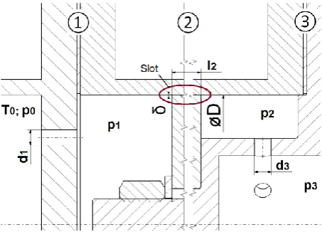
One example of possible designs of the unloading valve is shown in Figure 1. This is the valve designed by Professor A.E. Zarjankin from the Moscow Energy Institute. Doosan Skoda Power uses own specific design where the slot function is the same.
The steam of unloading system is led through a number of openings in the guide sleeve to the slot where it is throttled from the pressure p1 to the pressure p2.
Then the steam passing through the area under the bypass cone gets to the diffuser, where it expands to the pressure p3. The lift of valve cone and the pressure p3 is
determined by the turbine operation. The length of the slot changes with the lift of the cone as well. From a certain lift of the cone h the supply of the bypass steam from the slot is closed and the valve begins to work in the non-unloading mode. This causes the increase of the stabilization power acting on the valve cone again.
On the model of the bypass system of the valve shown in Figure 2, the aerodynamic parameters of three parts, i.e. the set of input openings, the slots themselves and the output section, can be examined. For the initial phase of experiments, eight openings with the diameter
d1 = 9 mm were chosen in order to model the input
section. The width of the slot δ = 0.3, 0.5 and 1 mm is considered. The slot with δ = 0.15 mm has also been tested. In this case the problems with the correct evaluation of the mass flow already occur. The experiments are also completed with the variant of the slot with δ = 0.3 mm. The length of the slot is l = 50 mm
in all cases. The output section is created by six openings
d3 = 9.5 mm. The model itself is connected to the
compressed air distribution, which enables its expansion from the pressure at the level about 7.5 bar (a) to the barometric pressure. In addition to the experiments the flow on the model of the valve was verified using numerical simulations
.
Fig. 2. Model of the bypass system of the valve
3
Modelling the flow in the slot using
the numerical simulation
A part of the experimental test rig containing the throttling slot is considered for the computations themselves. This is the model of the bypass system of the valve which is presented in Figure 2. The total computational mesh is presented in Figure 3. For the numerical simulation of the air flow through the slot, the nonlinear system of Favre-averaged Navier-Stokes equations is considered. The system is completed by the Spalart-Allmaras turbulence model [2] for
Galerkin finite element method (DGFEM) is used for the spatial discretization of the system of equations [3, 4]. The advantages of the method are high order of spatial accuracy and low artificial dissipation. As the basis functions, the linear polynomials were considered. This choice ensured second order of accuracy in space. For the approximation of inviscid fluxes on the element boundaries, the numerical Lax-Friedrichs flux was used [5]. Similarly, the viscous fluxes are evaluated using the appropriate numerical fluxes. In present paper, the approximation known as interior penalty (IP) method was chosen. The developed software is applied for numerical simulations of the flow in the slot having the width 0.15, 0.3 and 1 mm for different pressure gradients.
Fig. 3. Computational mesh of the model of the bypass system
The computations were compared with the experiments. The measurement was carried out for two widths of the slot δ = 0.3 mm and δ = 1 mm with the same length l = 50 mm. Comparison of computational mass flow rate with the experimentally measured data is presented in Figure 4 and 5. A good agreement for the tested examples is verified.
Fig. 5. Computational and experimentally evaluated mass flow through the slot having the width δ = 1 mm and l/δ = 50
By using computational studies it is possible to verify whether modelling is applied for slots when the geometric similarity is maintained. The slot having the width δ = 0.3 mm was used as the base. The comparison with the slots having the widths δ = 0.5 mm and
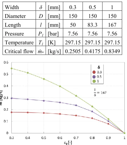
δ = 1 mm was carried out. Considered dimensions and air input parameters are shown in Table 1. Computed mass flows are shown in Figure 6.
Table 1. Dimensions and input parameters
Width δ [mm] 0.3 0.5 1 Diameter D [mm] 150 150 150 Length l [mm] 50 83.3 167 Pressure P1 [bar] 7.56 7.56 7.56
Temperature T1 [K] 297.15 297.15 297.15
Critical flow ṁ* [kg/s] 0.2505 0.4175 0.8349
Fig. 6. Mass flows through the slots having different widths and the same ratio l/δ
The same diameter, on which the slot is located, was considered. However, the length of the slot was used to keep the ratio l/δ in all cases. Comparison of flows in dimensionless parameters is presented in Figure 7
.
Fig. 7. Mass flows through the slots for l/δ = 167
Assuming that modelling is kept, the dimensionless flow for all three slots should be the same. However, with the increasing width of the slot at the same pressure ratios the dimensionless mass flow decreases. There is only a small difference between the variants with
δ = 0.3 mm and 0.5 mm. However, there is a significant difference in the variant with the slot δ = 1 mm. It might be expected that with the increasing width of the slot the influence of the friction in the boundary layer on the total flow will be reduced and therefore the flow will increase. According to the computations carried out the flow is influenced by the length of the slot and the relevant influence on l/δ is not linear. For comparison, the correction of the flow from the variant δ = 0.3 mm
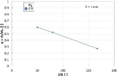
and l = 50 mm for the arrangement with δ = 0.5 mm and
δ = 1 mm for the same slot l = 50 mm is presented in Figure. 8. The same average velocity for all slots is assumed. In this case with the increasing width of the slot, the mass flow increases. Never the less, the parameter l/δ changes. The flow decreases with the increase of the value l/δ. The length of the slot has a major influence on the resulting mass flow.
Fig. 8. Correction of the proportional flow q for δ = 0.3 m for other widths of the slot
A series of computations of the flow through the slot having δ = 0.3 mm and length l = 1 ÷ 80 mm was carried out. When evaluating the dimensionless parameter
flows are shown in Figure 9. With increasing length of the slot the relative mass flow decreases.
Fig. 9. Influence of the relative length l/δ on the relative flow q for the slot having δ = 0.3 mm
As its course for the constant pressure ratio 2 = 0.4
and 2 = 0.8 in Figure 10 shows, this is not linear dependence q on relative length l/δ.
Fig. 10. Dependence of the relative mass flow q on the relative length of the slot
Similar findings concerning the slot having the width
δ = 0.3 mm are applied for the slot with δ = 0.5 mm as well. The results from computations and experiments are shown in Figure 11 and 12.
Fig. 11. Influence of the relative length l/δ on the relative flow q for the slot having δ = 0.5 mm
Fig. 12. Dependence of the relative mass flow q on the relative length of the slot
The data for the slot with the width δ = 1 mm are also available from the computations and experiments. Dependence of the relative flow q on the pressure ratio
2 and on the relative length of the slot is presented in
Figure 13 and Figure 14.
Fig. 13. Influence of the relative length l/δ on the relative flow q for the slot having δ = 1 mm
Fig. 14. Dependence of the relative mass flow q on the relative length of the slot
The CFD study shows a rather significant decrease of the flow for the slot having δ = 1 mm at a longer length and the pressure ratio 2 0.5. It is not clear what causes
This is the area out of the course q = f (2) with more significant uncertainty of the dependence.
The numerical simulation enables evaluation of courses of aerodynamic parameters in all parts of the tested model. It particularly concerns the distribution of the pressure, velocity, Mach number and Reynolds number
Three pressure ratios for all model arrangement are considered. How the pressure ratios on the slot are different from the pressure ratio across all model is presented in Table 2.
Immediately at the inlet of the slot there is a sudden decrease of the pressure and a sudden increase in velocity. For the slot with the width δ = 0.15 mm the aerodynamic blockage was achieved at the exit from the slot.
Table 2. Pressure ratios
δ = p3/p0 ṁ = p2/p1 q [mm] [-] [kg/s] [-] [-]
0.15
0.35 0.062 0.43 0.611 0.55 0.058 0.6 0.572 0.85 0.02 0.92 0.197
0.3
0.35 0.135 0.52 0.665 0.55 0.122 0.67 0.601 0.85 0.065 0.92 0.32
Two pressure ratios are considered on the slot. The flow separation at the inlet of the slot and reduction of the flow area is characteristic. At the outlet from the slot, the flow clings to the outer limiting wall. At the pressure ratio 2 = 0.3, the maximum velocity occurs behind the slot, but at the higher pressure ratio the maximum velocity already occurs inside the slot.
4 Conclusion
It was investigated and validated that the discontinuous Galerkin method is an appropriate tool to describe the flows in the slots of different dimensional configurations. The acceptable agreement between experiments and computations was verified. The linear dependence of the mass flow on the relative length of the slow is not verified. However, for the area of real values
l/δ on the control valves the linear dependence is acceptable. The numerical simulation enables mapping velocity and the pressure field across the entire flow area of the tested model. Pressure ratios on the slot itself differ from the pressure ratios on the whole model.
5 Acknowledgements
This study was supported by the project L01506 of the Ministry of Education, Youth and Sports of the Czech Republic and by the internal grant project SGS-2016-038 of the University of West Bohemia.
References
1. L. Mrózek, L. Tajč, Modelling of flow in the unloading slot of the control valve (AIP Conference Proceedings 1889, 020024 (2017), http://dx.doi.org/10.1063/1.5004358)
2. P. R. Spalart, S. R. Allmaras, A One-Equation Turbulence model for Aerodynamic Flows (AIAA Paper 92-439 (1992)).
3. B. Cockburn, C.-W. Shu, Runge-Kutta Disconti-nuous Galerkin Methods for Convection- Dominated Problems (Journal of Scientific Computing 16 (3), 173-261, 2001).
4. J. Vimmr, O. Bublík, A. Pecka, A parallel implementation of an implicit discontinuous Galerkin finite element scheme for fluid flow problems (Advances in Engineering Software, article in press,
http://dx.doi.org/10.1016/j.advengsoft.2016.11.007) 5. E. F. Toro: Riemann Solvers and Numerical