Advanced Microprocessor Based
Intelligent Relay for
Multifunction Protection System
VICTORIA °
UNIVERSITY
z
o
o
o
-<
Zejian Chen
B. E. (China), M. E. (AustraUa)
A Thesis Submitted to the Department of Electrical and Electronics
Engineering for the Research Degree of
Doctor of Philosophy
FTS THESIS
To
My parents
Contents
Contents
Contents I
List of Figures VIII
List of Tables XIII
List of Principal Symbols and Abbreviations XIV
Abstract XVII
Statement of Originality XX
Preface XXI
Acknowledgments XXIII
Chapter 1. Introduction
1.1 The Aim of the Protection 1
1.2 The Fundamental Concept of Relays 2
1.3 Design Criteria of Protective Relays 4
1.4 Statement of the Problem and Design 5
1.5 Research Methodology 9
1.6 Motivation of the Thesis 12
1.7 Contributions of the Thesis 13
1.8 Organisation of the Thesis 14
Chapter 2. Literature Review
2.1 Introduction 15
2.2 Microprocessor - Based Relays 15
Contents
2.2.2 Benefits of Microprocessor - Based Relays 18
2.3 Digital Multi-function Protective Relay 23
2.3.1 Review of the Digital Multi-ftinction Protective Relays 23
2.3.2 Benefits of Digital Multi-fiinction Protective Relays 24
2.4 Neural-Network Application in Power System Operation and Protection 25
2.4.1 Review of Neural-Network Application in Power System 25
2.4.2 Potential of Artificial Neural Networks in Power System Operation and
Protection 28
2.5 Conclusion 29
Chapter 3. Design of Experimental System Used in the Power Laboratory
3.1 Introduction 30
3.2 A Three phase Power System Model 30
3.3 Theory of Transmission Line 31
3.4 Design of Transmission Line 35
3.5 A,B,C,D Constants of Transmission Line 38
3.3 Conclusions 41
Chapter 4. A Developed Multi-Curves and Hybrid Characteristics
Over-current Protection
4.1 Introduction 42
4.2 The Concept of Overcurrent Characteristics and Protection Practices 43
Contents ^
4.2 The Concept of Overcurrent Characteristics and Protection Practices 43
4.3 Design of Multi-input and Hybrid Characteristics Overcurrent Protection 51
4.4 Implemented Software Design 56
4.5 Conclusion 60
Chapter 5. Substation Bus-Bar Differential Protection
5.1 Introduction 61
5.2 Principle of Differential Protection 63
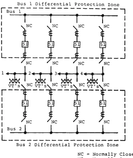
5.3 Substation Bus-Bar Protection 65
5.3.1 Principle of Bus-Bar Protection 65
5.3.2 Current Transformer Saturation 74
5.4 Design of Microprocessor Based Busbar Protection with Current
Transformer Saturation Detector 77
5.4.1 Digital Busbar Protection 77
5.5 Implemented Software Design 85
5.6 Conclusions 87
Chapter 6. Design of Intelligent Embedded System for Fault Classification
6.1 Introduction 88
6.2 Design Principle of Artificial Neural Network 91
6.2.1 The Basic Structure of Neural Network 91
6.2.2 Neuron Modeling for Artificial Neural System 92
6.2.3 The Neural Network 94
Contents
6.4 Current Application of Neural Network 99
6.5 The Learning Algorithms as Using in Our Design 100
6.6 Design of Fault Classification by Using ANN in Power Protective System 101
6.7 Training and Testing 109
6.8 Implemented Software Design 115
6.9 Conclusions 117
Chapter 7. Implemented System Design
7.1 Introduction 118
7.2 System Hardware Design 121
7.2.1 Evolution of the Microprocessor 121
7.2.2 The Microprocessor System 123
7.2.2.1 Hardware and Firmware Features 123
7.2.2.2 Main Processor and Features 126
7.2.2.3 Co-Processor 128
7.2.2.4 EPROM Memory 129
7.2.2.5 RAM Memory 129
7.2.2.6 MC68230 Peripheral Interface/Timer (PI/T) 129
7.2.2.7 MC68681 Dual Asynchronous Receiver/Transmitter
(DUART) 130
7.2.2.8 Processor Bus Interface 130
7.2.2.9 Power Supplies 130
7.2.2.10 Memory Map 133
Contents
7.2.3.1 The Software Development System - Overview 134
7.2.3.2 The Software Development System - Invocation 137
7.2.4 The Interfacing System Design 138
7.2.4.1 Analogue to Digital Converter Design 140
7.2.4.2 Low-Pass Filter Design 141
7.2.4.3 Pre-Amplifier Design 144
7.2.4.4 Galvanic Isolation Transformer 146
7.3 System Software Design 146
7.4 Conclusions 150
Chapter 8. A Developed Computer System for Testing Response of a
Protective Relay
8.1 Introduction 151
8.2 The Digitally Synthesised Test System Hardware Design 154
8.3 The Digitally Synthesised Test System Software Design
.160
8.3.1 Creating a Data File for Simulation on ATP4 - 161
8.3.2 Running the Simulated Program on ATP4 162
8.3.3 Creating a Data File to Simulate AC Signals 162
8.4 Fauh Simulation by Using ATP4 164
8.5 Implementation of the Designed System 166
Contents
Chapter 9. Test and Laboratory Implementation Studies
9.1 Introduction 171
9.2 Test Studies 171
9.2.1 Test of Overcurrent Protection Schemes with ANN Fault
Classification Function 173
9.2.2 Test of Differential Protection Scheme 177
9.3 Laboratory Implementation Study 182
9.3.1 Implementation of Overcurrent Protection Schemes with ANN Fault
Classification Fvmction 183
9.3.2 Implementation of Differential Protection Scheme 186
9.4 Conclusions 187
Chapter 10. Conclusions
10.1 A Retrospective Overview of the Thesis 189
10.2 Avenues to be Explored in Further Work 191
Appendix
Appendix A 193
A.l Per Unit Calculation for Transmission Line 193
A.2 The Derivation of A, B, C, D Constants 194
A.3 The Calculation of A, B, C, D Constants 198
Appendix B 203
Contents
Appendix D 210
D.l FLIGHT-68020 EVM Specification 210
D.2 Board Layout 212
D.3 Connectors P4 & P5 (DUART & PI/T) 213
D.4 Bus Pinout Details 216
D.5 FLIGHT-68020 EVM Memory Map 217
D.6 The Detail of AD7828 Circuit Connection 218
D.7 The Detail of the Design Circuit Connections 219
Appendix E 223
E.l Digital to Analogue Conversion Software . 223
E.2 Connection Detail of DAC 228
E.3 Input Card-Deck Structure for Transient Analysis 235
E.4 Active Fourth Order Filter Design 238
E.5 Sample Data File for ATP4 Simulation (Transients) 243
E.6 Digital Synthesis of Protection Test Waveform User Guide 246
Appendix F .253
List of Figure
List of Figures
1.1 An application of protective relay in generation plant 7
1.2 The protection system configuration in the substation 9
1.3 Basic configuration of microprocessor based multi-function protection system 10
2.1 The functional block diagram of a digital computer based relay 18
3.1 Analogue model and experimental set-up 31
3.2 Generator supplying a balanced-Y load through a short transmission line 33
3.3 Equivalent circuit of a short transmission line 33
3.4 Nominal-7t circuit of a medium-length line 34
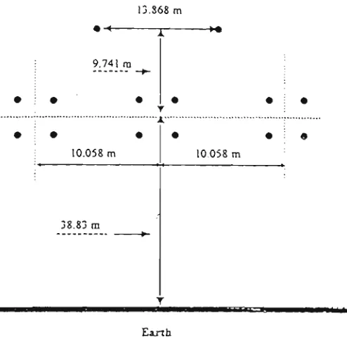
3.5 Line configuration 37
3.6 The design circuit of transmission line 38
3.7 Single phase line 39
3.8 Schematic diagram of a transmission line showing one phase and the neutral
return. Nomenclature for the line and the elemental length are indicated 40
4.1 Time-current characteristics 44
4.2 Time discriminating using definite time lag relays 46
4.3a Inverse time-current characteristics 47
4.3b Fault clearance time discrimination between different protected zones 47
4.4 Standard IDMT curves 49
4.5 Various time-current curves 50
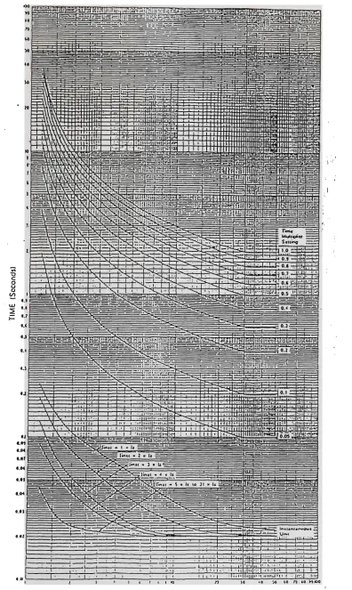
4.6 Typical family of inverse type operating time characteristics for the
various time multiplier settings 52
List of Figure
4.8 Typical inverse-time overcurrent relay characteristics' curves 54
4.9 A combined use of definite and inverse time characteristics' curves 55
4.10 A flowchart of the overcurrent protection system software routine 56
4.11 A flowchart of first section of relay 58
5.1 A differential current protection of single busbar 62
5.2 Basic current differential scheme illustrated for the Protection of a zone with two
circuits: (a) normal conditions, Iop=Ie"-Ic'; (b) internal fault, Iop=lFi+lF2-(I«'+Ie") . . . 64
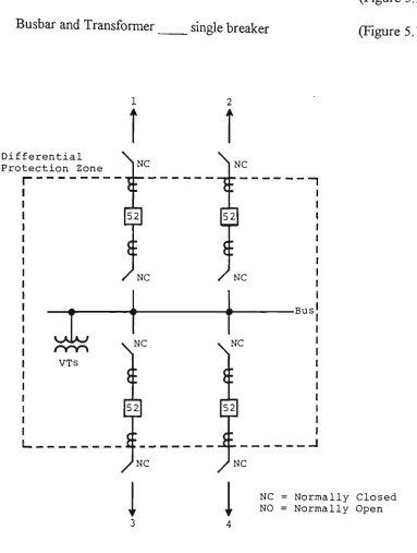
5.3 Typical four-circuit single breaker-single bus and the bus
differential protection zone 66
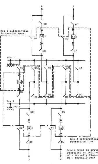
5.4 Typical four-circuit single breaker-double bus with bus tie, and the
bus differential protection zones 67
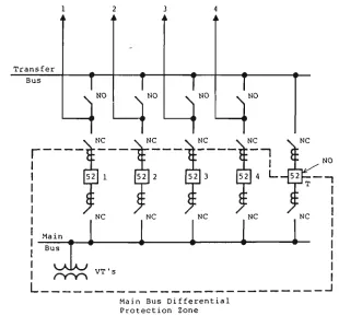
5.5 Typical four-circuit single breaker-main bus with transfer bus, and the
bus differential protection zone 67
5.6 Typical four-circuit single breaker-double bus and the bus
differential protection zones 68
5.7 Typical four-circuit double breaker-double bus and the bus
differential protection zones 69
5.8 Typical four-circuit ring bus. Differential protection not applicable. Bus
sections are protected as part of the lines or connected equipment,
as shown dotted 69
5.9 Typical four-circuit breaker-and-a-half bus and the bus differential
protection zones. The mid-bus sections are protected as part of the
lines or connected equipment, as shown dotted 70
5.10 Typical four-circuit single breaker bus and transformer with
List of Figure
5.11 Percentage-differential characteristics for bus or transformer protection 74
5.12 Theoretical wave form of secondary current with offset primary current
(ip - Primary current; i. - secondary current; O - total flux) 75
5.13 Current immediately after fault inception 76
5.14 Dc saturation of current transformer 76
5.15 A functional block diagram of busbar differential protection
with saturation detector 78
5.16 Typical through current characteristics of various differential type relays 80
5.17 Current transformer secondary current waveforms and differential current for an
external fault with current transformer saturation 84
5.18 A flowchart of bus-bar protection relaying 86
6.1 Representation of a biological neuron 91
6.2 General symbol of neuron consisting of processing node and synaptic connections . . .92
6.3 Interconnecting neural network (Hopfield neural network). Vi indicates the state of
the system, Xi indicates the initial value of the node, and xj' indicates the output
value after convergence 95
6.4 Multilayer neural network. The solid line indicates the physical signal flow,
whereas the dotted line indicates the back propagation 95
6.5 A layered model of semantics in neural classifying modules 102
6.6 Structure of a typical neural network 103
6.7 A training system of the neural network 104
6.8 A flowchart of the main program 105
6.9 A flowchart of the learning function 106
List of Figure
6.11 A flowchart of the learning algorithm function 108
6.12 The structure of ANN's for fault classification I l l
6.13 The convergences of the pattern error at different training conditions 113
6.14 Recall phase of the neural network 113
6.15 A flowchart of implemented program 115
7.1 The block diagram of microprocessor based relaying system 120
7.2 Block diagram of the Flight-68020 EVM system board 124
7.3 Internal architecture block diagram of MC68020 CPU 126
7.4 Internal architecture block diagram of MC68020 (Coprocessor) 128
7.5 Functional block diagram of MC68020 (PI/T) 131
7.6 Functional block diagram of MC68020 (DUART) 132
7.7 Block diagram of the relay interface 139
7.8 A functional block diagram of AD7828 141
7.9 The AD7828 operational diagram 142
7.10 An ideal low-pass filter characteristic 143
7.11 Functional block diagram of MFIO 144
7.12 Schematic circuit diagram of low-pass filter 145
7.13 The schematic circuit diagram of preamplifier 146
7.14 The system program structure 148
8.1 A computer based testing simulator 153
8.2 Block diagram of equipment used to digitally synthesis test waveforms 154
8.3 Circuit diagram of the injection diagram 160
8.4 Flow chart for the production of the AC signals 163
List of Figure
8.6 Series 1 - A single D/A converter output, Series 2 - signal conditioned
for relay testing 167
8.7 The generated three phase currents fault waveform at the output of the
interface circuits (phase to phase fault) 169
9.1 A structure of implemented multi-digital relaying system 172
9.2 A flat feeder simulated system 173
9.3 Standard inverse curves (IDMT) 175
9^4 Very inverse Curves 175
9.5 Extremely inverse curves 176
9.6 Single phase external fault (phase A) 178
9.7 Three phase external fault 179
9.8 Single phase internal bus fault 180
9.9 Three phase internal bus fault 181
9.10 The realistic implemented power system model . .182
9.11 Phase A to earth fault (at 21) 185
9.12 Oscillogram of the relay response at external fault with CT saturation 186
9.13 Oscillogram of relay response at internal fault 187
List of Table
List of Tables
3.1 Ratings of the generator and motor 31
6.1 Some major neural network models 97
6.2 Fault types for classification 110
6.3 The implemented template for training data 110
6.4 Output for trained data patterns 112
6.5 Test result of ANN's design 114
8.1 Detail pin description for the Quad DAC 158
8.2 The simulation cases 166
9.1 The tested results of proposed overcurrent relay 174
9.2 The simulated result of neural network fault 177
9.3 The implementation results of proposed overcurrent relay 183
List of Principal Symbols and Abbreviations
List of Principal Symbols and
Abbreviations
A A/D ALDAC ANN ATP4 AUs B CB CBS CT CTs CPU D DAC DACs Dc DMA EMTP EHV HVdimensionless since it is a ratio of two voltages
analogue to digital
asynchronous load digital to analogue converter
artificial neural networks
alternate transient program version 4
arithmetic units
the ratio of voltage at the sending end to current at the receiving end with the
receiving end short circuited
the ratio of current the sending end to voltage at the receiving end with the
received end open circuited
circuit braker
circuit breakers
current transformer
current transformers
central process unit
the ratio of sending end current to receiving end current with the receiving end
short circuited
digital to analogue converter
digital to analogue converters
direct current
direct memory
electro-magnetic transient program
the measure of the error on input/output pattern p, E = EEp is the overall
measure of the error
extremely high vohage
List of Principal Symbols and Abbreviations
I
I + AI
Id In lop Ip IR K Ka k. LDAC MLP Opj P PSM RAM ROM T tm tpj 1 phase Iphase'n ••-phase'p RSM V
V + AV
VR w
Wji
y Ax
the current flowing out of the element toward the load
the current flowing into the element from the generator
sum of current data at each terminal
sum of current data at each terminal which is negative
relay operating current
sum of current data at each terminal which is positive
receiving end current
the design constant
the percentage restrain factor
design constant ( k, < 1 )
load digital to analogue converter
multi-layer perceptron
the jth element of the actual output pattern
the number of training patterns.
plug setting multiplier
random assess memory
read only memory
the theoretical operating time of the relay
the time multiplier setting
the target input for the Jth component of the output pattern for pattern p
phase counter
negative half cycle phase counter
positive half cycle phase counter
time setting muhiplier
the voltage to neutral at the end of the element toward the load
the voltage at the end of the element toward the generator
the receiving-end voltage
the weight vector
a weight of connection from jth to ith unit
the distance measured from the receiving end of the line to the small element of
line
List of Principal Symbols and Abbreviations
z Ax the series impedance of the elemental length of the line
Zc the characteristic impedance of the line
Zs the source impedance
Y the propagation constant
5pj an error term for unit j
AI the current entering the element from the generator end is higher than the
current flowing away fi^om the element in the direction of the load by the
amount
Ala the change in the differential current U
Alp + AIn the change in the restraining current
ApWji the change to be made to the weight fi-om the ith to jth unit following
presentation of pattern p
AV the rise in voltage over the elemental length of line in the direction of increasing
x
Abstract
Abstract
Protective relay constantly monitors the power to assure maximum continuity of electrical
service with minimum damage to life and property. Thus, they are on guard throughout - from
the generation, through transmission, into distribution and utilisation. They are found in large
and small systems, in the power companies and in most industrial installations. This wide
usage, with high demands for reliable operation, has created a continuing desire for additional
tasking. In power protection field, there have been many cases where protection theories and
techniques have played an important role. With the progress of protection techniques, there are
now many applications for protection with increased performance. However, applicable
systems become increasingly complicated and highly composite. It is therefore expected that
protection techniques will make further progress. The recent advancements of digital
technology associated with the power industry has had further impact on development of
power system protection equipment and techniques. The low cost, high performance
microprocessor has led to their increasing use in digital relaying techniques. The 32-bit
microcomputer boards with their high speed, high computing power, as well as its high level
language feature, provides special possibilities of implementing an intelligent multi-function
relay for substation protection system with the required speed, accuracy and reliability. The
availability of microprocessor at economic cost has allowed a new concept of multi-function in
the field of protection relays. The digital multi-function protective relay has capability of
providing multi-tasking, multi-digital relaying function with high reliability and open-end
facilities for integrating multi-protection schemes.
For protective system improvement, such tasking is valuable not only to those directly
responsible but also to the many others indirectly associated with protection techniques, such
as fault detection, identification and diagnosis is currently a very important problem in the
protection process. Recently, many researchers have developed neural networks as new tools in
many fields, such as pattern recognition, information processing and control design. However,
numerous researchers have explored ways in which artificial neural networks may apply to the
electric power industry. Those applications which interest users most are focused on electric
Abstract
In this thesis, research has been conducted on the design and implementation of an advance
microprocessor based intelligent relay for multi-function protection system. The developed
project utilises knowledge and principle of overcurrent and differential protection schemes, as
well as neural network and advanced microprocessor based relay modular format system
incorporating high flexibility, high response speed, high communication ability and high
artificial intelligence ability.
It checks the performance of the developed software and hardware, and verifies its
effectiveness. It also demonstrates a modular architecture that allows scope for further
enhancement of future algorithms.
In order to carry out the investigation into the above design, work was done in the following
stages:
* Design of experimental system model for use in the power laboratory;
* Design of a developed multi-curves and hybrid characteristics overcurrent protection;
* Design of an improved differential protection schemes with high operating speed, high
sensitivity and security for substation busbar protection system;
* Design of intelligent embedded system for fault classification which can be used to
operate a protective relay;
* Design of the implemented hardware and software system;
* Design of a developed computer system for testing response of the protective relay;
* Test and implementation of the proposed design in the power laboratory.
The laboratory experimental set-up and the analogue model is designed using a 5 kVA
generator, 400V and 400km long three phase transmission line with four n sections and the
appropriate bus-bars. Then the microprocessor based multi-function protection relay was
Abstract
Finally, the proposed design of advanced microprocessor based intelligent relay for
multi-function protection system has been tested by using a developed computer based test system.
The overall performance of the multi-digital relays during different fault conditions test and
Statement of Originality
Statement of Originality
"I hereby certify that the work embodied in this thesis is the result of original research and has
not been submitted for a higher degree to any other University or Institution.
This thesis may be made available for consultation within the University Library and may be
photocopied or lent to libraries for the purposes of consultation if accepted for the award of
the degree.
(Signed)
Preface
Preface
My doctoral studies were conducted under the guidance of Associate Professor. Dr. Akhtar
Kalam and Dr. Aladin Zayegh as supervisors. Most of the research results reported in this
thesis have been presented and published in referred conference proceedings. These papers
are:
1. Z. Chen, A. Kalam, A. Zayegh, "Advanced Microprocessor Based Power Protection
System Using Artificial Neural Network Techniques". Proceeding of IEEE
International Conference on Energy Management and Power Delivery. EMPD'95
Singapore, Vol. 1, pp.439-444, Singapore, 21-23 November, 1995, ffiEE Catalogue
No 95TH8130.
2. Z. Chen, A. Zayegh, A. Kalam, " Advanced Microprocessor Based Miilti-Digital
Protection Relaying" Proceeding of IEEE International Conference on Power System
Technology, 18-21 October 1994, Beijing, China, Vol.2, pp. 1110-1114.
3. Z. Chen, A. Zayegh, A. Kalam, "Intelligent Relay for Substation Protection System"
Proceedings of the Australia Universities Power Engineering Conference, 27-29
September 1994, Vol.2, pp. 387-392.
4. Z. Chen, A. Zayegh, A. Kalam, "New Approach to Implement Multi-Protection
Schemes in Distribution System Based on Third Generation Microprocessor"
Proceedings of the Australia Universities Power Engineering Conference, 29th-1st
1993, Vol.2, pp. 355-360.
5. Z. Chen, A. Zayegh, A. Kalam, "Advanced Microprocessor Based Multi-Digital
Protection Schemes" Proceedings of Distribution 2000 Conference, 9-12 November
Preface
6. Z. Chen, A. Zayegh, A. Kalam, "Advanced Microprocessor Techniques to Simulate
Overcurrent and Differential Protection System", Jordan International Power System
Conference, October 4-6, 1993, AMMAN-Jordan. pp. 182-187.
7. Z. Chen, A. Zayegh, A. Kalam, "32-bit Mcroprocessor Adaptive Techniques to
Simulate Multi-Digital Protection Schemes" Proceeding, 2nd International Conference
on "Modellmg & Simulation", Melbourne, Australia, July 12-14, 1993, Vol. 1,
pp.287-295.
8. A. Zayegh, A. Kalam, Z. Chen, "32-bit Microprocessor Based Digital Relaying
Techniques for Overcurrent and Differential Protection" Proceeding Intern. AMSE.
Acknowledgments
Acknowledgments
I wish to express sincere appreciation to Dr. Akhtar Kalam and Dr. Aladin Zayegh for their
constructive guidance, advice and assistance which helped me in this research work and
completing of this thesis.
My acknowledgment and gratitude also go to Mr. Ralph Phillips for his skilful assistance in
setting up the equipment in the Power Laboratory.
I sincerely thank Mr. P. Im for his kind advice and help on the software, and Mr. R. Rodrigo
for his assistance on the design of computer based test system, which resulted considerable
saving of valuable time.
I grateful to the committee for Postgraduate Studies of Victoria University of Technology for
providing me with the scholarship and assistance to attend international conferences.
Finally, I wish to dedicate this thesis to my parents. They have brought me up with all the love,
understanding and wisdom for which I am greatly indebted. I would also like to express my
gratitude to my wife Lanfang Ren for her encouragement and support to accomplish my
Chapter 1
Chapter 1
Introduction
1.1 The Aim of the Protection
The first aim of the protection is to intervene in the electricity grid in case of a fault. To prevent
further damage, a part of the grid (containing the faulted component) should be disconnected.
This can reduce the availability and thus increase the probability of interruption. It can also
influence the load-flow. Sometimes it can reduce a load burden (e.g. by load shedding) but
generally it increases the loading of the remaining components, thus increasing the probability
of an interruption. To prevent an interruption of the electricity supply as much as possible, the
second aim of the protection is to disconnect no more components than necessary, even in case
of a failure of the protection. To fulfil both tasks as far as possible the power system is divided
into "zones": this is the smallest part of the electrical network that can be disconnected from
the rest of the system.
In general the term "zone" is used for the part of the network in which a fault is actually
detected by a relay [1]. When assessing the reliability of protection, this "protected region"
will be of a stochastic nature. The setting of the relay is not known, nor are the type of fault or
the exact network parameters. The term "zone" is suggested to use in reliability analysis as the
ideal "protected region". Such zones will be separated from each other by circuit breakers.
In case of a fault within a certain zone, the primary protection needs to disconnect this zone. In
case a fault influences two or more zones, then it will be considered as separate faults. Each
Chapter 1
situation occurs for a fault in a circuit breaker or for a double-circuit fault on a multi-circuit
line.
In case of a failure of the primary protection the fault needs to be disconnected by a local
backup (disconnecting only the faulted zone) or by a remote backup (disconnecting
non-faulted zones too). This is again a slight deviation fi-om the standard definition in which a local
back-up is situated in the same station as the primary protection and the remote back-up in
another station.
1.2 The Fundamental Concept of Relays
A relay is a device which makes measurement or receives a controlling signal in consequence
of which it makes sudden pre-determined changes in one or more electrical circuits [2].
Relays can be divided into five functional categories [3]:
a. Protective Relays, which detect defective lines, defective apparatus, or other
dangerous or intolerable conditions. These relays can either initiate or permit switching
or simply provide an alarm.
b. Monitoring Relays, which verify conditions on the power system or in the protection
system. These relays include fault detectors, alarm units, channel-monitoring relays,
synchronism verification, and network phasing. Power system conditions that do not
involve opening circuit breakers during fauhs can be monitored by verification relays.
c. Programming Relays, which establish or detect electrical sequences. Programming
relays are used for reclosing and synchronising.
d. Regulating Relavs. which are activated when an operating parameter deviates fi^om
pre-determined limits. Regulating relays function through supplementary equipment to
Chapter 1
e. Auxiliary Relays, which operate in response to the opening or closing of the operating
circuit to supplement another relay or device. These include timers, contact multiplier
relays, sealing units, receiver relays, lock-out relays, closing relays and trip relays.
A protective relay responds to abnormal conditions in an electrical power system and controls a
circuit-breaker so as to isolate the faulty section of the system, with minimum interruption to
service. Relays may be segregated into two classes in line with the definition: those which
measure and those which merely repeat a controlling signal. These relays may have a simple
contactor type function, but in some cases may also make a measurement. For example, a
time-delay relay may be energised as an all-or-nothing device but may then measure a precise period
of time before closing an output contact.
The nominal minimum value of the measured quantity at which a relay operates is called the
'setting'. Strictly, the term 'setting' should be confined to that quantity which is set either
during calibration or selected in application. In many cases, this value is synonymous with the
minimum operating quantity, but this is not always so. The term setting should be confined to
the calibrated quantity, in this case the voltage will cause operation when applied to the relay.
The current input to the relay at the voltage setting is the 'relay operating current'. Similarly,
the test-current which would have to be injected into the secondary circuit to produce operation
is the 'effective secondary operating current', and the primary counterpart of this is the
'primary operating current'.
Protective relays remain inoperative, although energised for very long periods while the
power-system is healthy, and yet must operate decisively when required to do so. The incidence of a
fault requiring operation may not be as frequent as once in twenty years. Reliability is therefore
of paramount importance. This is not synonymous with robustness. There is a natural
reluctance to ti^ust the security of a large machine or high power circuit to a delicate relay
movement or small component, but in fact when used correctly these items may well be more
Chapter 1
1.3 Design Criteria of Protective Relays
The application logic of protective relays divides the power system into several zones, each
requiring its own group of relays. Some of the terms that are impotent to understanding the
basic principles of the protection system are: [66]
Stability: This term refers to the ability of the system to remain inoperative to all load
conditions and faults external to the relevant zone. This quality is present in unit system, as
they remain inoperative under all conditions, with faults outside their own zone. However,
non-unit systems can respond to faults anywhere on the power system.
Selectivity: Protection is arranged in zones so as to assure no part is left unprotected. When a
fault occurs the protection is required to select and trip the nearest circuit breakers only. Also
known widely as "Discrimination". In the non-unit systems the discrimination is not absolute,
but it is dependant on responses of a number of similar systems, all of which respond to a given
abnormal condition. However, for the unit systems, the discrimination is absolute and it is able
to detect and respond to abnormal condition occurring within the zone of protection.
Sensitivity: This term is frequently used when referring to the minimum operating current of a
complete protective system. Hence protective system is sensitive, if the primary current is low.
The requirements of all relays should be quite sensitive for reliable operation. This term is
usually expressed in amperes referred to the primary circuit or as a percentage of the rated
current of the current transformers.
Reliability: Power system represents a large capital investment and in order to get maximum
return it must be loaded to its maximum. The purpose of power system is not only to supply
energy but also to keep the system in full operation, in order to give the best service to the
consumers and earn revenue for the supply authority. Failure is not confined to the protective
gear but may also be due to the failure of the circuit breaker. Hence every component involved
Chapter 1
Failures can be reduced by:
* reliable designs
* regular maintenance
* site testing.
Speed: The objective of speed is to safeguard continuity of supply. Hence if fault can be
isolated in the shortest time, the greater the system can be loaded as a function of fault clearing
times for various types of faults. Also fault involving phases has marked effect on stability
compared with the line-to-earth faults. The other advantage of having fast clearance times is
that unnecessary changes can occur in the system due to:
* high fault arc
* bum copper conductors
* machine or transformer lamination weld.
Fault currents can cause irreparable damage if allowed to continue for more than a few
seconds. Hence fast fault clearance is imperative.
Simplicity: As in any other engineering discipline, simplicity in a protective relay system is
always the hallmark of good design. The simplest relay system, however, is not always the
most economical. As previously indicated, major economies are possible with a complex relay
system that uses a minimum number of circuit breakers. Other factors being equal, simplicity
of design improves system reliability and this is only because there are fewer elements that can
malfunction.
1.4 Statement of the Problem and Design
Protective relay constantly monitors the system condition to assure maximum continuity of
Chapter 1
throughout - from the generation, through transmission, into distribution and utilisation. They
are found in large and small systems, in the power companies and in most industrial
installations. Figurel.l shows an application of protective relay in generation plant. This wide
usage, with high demands for reliable operation, has created a continuing desire for additional
tasking. For protective system improvement, such tasking is valuable not only to those directly
responsible but also to the many others indirectly associated with protection techniques, such
as fault detection, identification and diagnosis is currently a very important problem in the
protection process.
The early relays designed for the protection of power system used electro-mechanical
technology. Even today, several thousand relays using these relays are in operation around the
world. The elecfro-mechanical type relay is not only difficult to combine as a number of
traditionally isolated protection function together, but also it is almost impossible to identify
and analyse all operating conditions of concern in advance. They:
1) lack sufficient sensitivity;
2) exhibit relatively slow response time;
3) lack automatic periodic testing features;
4) lack automatic adjustment of reclosing sequence.
It is important to analyse the fault type as the first step in protection, as the operation of power
system requires extremely quick judgment. Therefore, the developed protective relay system
for estimating faulted section, such as multi-fault detection and fauh classification is now of
Chapter 1
V
Y C>u.
m
•s
ir-
HHI—i-jr.
— 3
£--b - u. u.
CD
- G O - - 1
O M -< ^ t - CD S
u i u . a : a : ° g 5 § g ' °
Q C _ i m c Q t / } C D O U . S £
us o
S > OC I - •-»
U . IL.
a Q a u . ^ i £ ? o o > a : i - « - » a : » - >
C £ _ J ( n c Q t f l O O U - C D C C S t D X
ui ca C3
r-a>-§-i-§
r —
-3£-•3e-H
cl
i:---i:-—
i:-—3&-§-i:----3E
idQ
^— - 3 9-K
a,
o
•I—(-a
<Da
4) .>: o <D 4—> O l - iChapter 1
In power protection field, there have been many cases where protection theories and techniques
have played an important role. With the progress of protection techniques, there are now many
applications for protection with increased performance. However, applicable systems have
become increasingly complicated and highly composite. It is therefore expected that protection
techniques will make further progress.
Modem power systems are required to generate and supply high quality electric energy to
customers [6]. To achieve this requirement, advanced microprocessor-based systems have been
applied to power system monitoring, control and protection.
The recent advancements of digital technology associated with the power industry has had
strong impact on development of power system protection equipment and techniques. The low
cost, high performance microprocessor has led to their increasing use in digital relaying
techniques [7-8].
The 32-bit microcomputer boards with their high speed, high computing power, as well as its
high level language feature, provide special possibilities of implementing a intelligent
multi-function relay for substation protection system with the required speed, accuracy and
reliability.
Figure 1.2 shows the protection system configuration in the substation. Schemes of protection
based on the overcurrent and differential principle are in wide application covering most of the
major protective items of power system including generator, transformers, transmission line,
bus-bar, etc. Clearly, there is a need for several different type of relays in a typical substation.
The design and implementation of advanced microprocessor based intelligent relay for
multi-function protection system is carried out in this thesis. The design incorporates three developed
techniques in one relay design. This includes overcurrent line protection, differential bus-bar
protection and line fault classification. Figure 1.3 shows the basic configuration of
Chapter 1
0 0 .
-
bt^-Figure 1.2 The protection system configuration in the substation
1.5 Research Methodology
The principle and knowledge of overcurrent relays, differential relays and artificial neural
networks are used to design and implement a secure power system protection algorithm. The
microprocessor programs that operate on the samples of voltage and/or current are written to
Chapter 1
important since it is necessary to model the system or the waveforms in order to develop an
algorithm. Most of the existing algorithms proposed for use in digital relaying can be grouped
into two categories. The first type is based on a model of the waveform itself, ie., the voltage
or current waveform. The second type involves a model of the system rather than the
waveforms. In this work, the first type is used for investigation of power system protection.
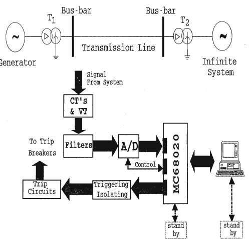
Bus-bar
Bus-bai
Generator
Transmission Line
signal
From System
To Trip
Breakers
Infinite
System
Figure 1.3 Basic configuration of microprocessor based
Chapter 1
Initially, suitable overcurrent and differential algorithms has been developed in the program for
bus-bar and transmission line in substation protection system. The performance of the relay
have been tested by digital synthesise of protection test equipment and then implemented under
ideal laboratory atmosphere subjected to several normal and abnormal conditions.
In addition, a new method for power fauh detection and classification in three-phase
transmission system based on the use of supervised leaming neural network technology and
adaptive pattem recognition concept are developed. The multi-layer network is introduced and
the problems in establishing neural network approaches based on this network for power
system protection application are discussed.
Subsequently, 32-bit microprocessor has been used to implement multiple overcurrent and
differential protection systems and intelligent fault classification schemes. Normally several of
these electro-mechanical and solid-state relays are used in a typical substation, for example,
three phases of a bus-bar or transmission lines are to be protected. Traditionally, protection is
carried out using both overcurrent and differential schemes. With the use of latest
microprocessor technology, these relay functions can be readily implemented by developing
the required algorithms. In the last two decades researchers and designers have made progress
in designing microprocessor based relays. A powerful 32-bit microprocessor system is a
flexible device, and can address a number of input and output devices. Consequently, it
providers signal to trip the appropriate circuit breaker, as deemed necessary. Furthermore, to
improve reliability all protection and classification software is duplicated and is executed
separately on two microprocessor system. To maximise the benefit of this design philosophy
the relay architecture is arranged so that the failure of any one hardware or software element
will not affect the operation of any other element or disable other operation of the
Chapter 1 ^ ^ ^
1.6 Motivation of the Thesis
This thesis involves the design and implementation of an advanced microprocessor based
intelligent relay for multi-function protection system. The intelligent multi-function relay is
designed to provide an attractive protection for bus-bar and transmission line. This includes
overcurrent line protection, differential bus-bar protection and line fault classification. The
objective is to incorporate the wide application of overcurrent and differential protection, and
up-date artificial neural network technique with modem digital technology to provide high
flexibility, high response speed, high communication ability, high intelligence and
multi-tasking relay for power system protection and to improve the reliability of power protection
system. Furthermore, it is also desired to incorporate as many of the required protection
function as is feasible into one package, thereby significantly reducing the expense.
No such adaptive device capable of providing reliable decision and comprehensive information
is available in current literatures. The development of this project will be a very useful tool to
protect major parts of the power system.
The impact of modem development in digital technology has been felt in many areas of power
system protection. Advanced microprocessor has gone through a rapid evolution over the last
ten years as evidenced by the continual increase in capabilities of advanced microprocessor
system. High speeds, large data size, larger program, data memories and high level language
feature and the availability of built-in peripheral functions have all led to substantial increase in
the power of microprocessor. When applied to protection relay these increases lead to faster
current sampling, improved reliability and the ability to combine a number of traditionally
isolated protection functions into a single multi-function protective device.
In this design, the relay as a pattem classifying device has been established. Artificial Neural
Network is biologically inspired and composed of elements that perform in a manner that is
analogous to the most elementary fimction of the biological neuron. The results show that the
neural network based approach contributed significantly with less diagnostic errors on test
datasets and the neural network are found to be able to perform the classification of multiple
Chapter 1
In order to test and simulate the design, a computer-based testing simulator has been
developed. This simulator is capable of producing vohage and current waveforms that
correspond to actual fault events in the power system. The results shown illustrate the
capability of this system to run real time simulations for testing relays.
Finally, the development of multi-function relay shows a great deal of flexibility and have the
ability to implement sophisticated protection algorithms efficientiy and economically.
1.7 Originality of the Thesis
The major contribution of this thesis are summarised as follows:
1) Design and development of a new approach to an advanced micro-processor based
intelligent relay for multi-function protection system.
2) The overcurrent and differential protection, and the neural networks for fault
classifications which has been developed on a 32-bit microprocessor based modular
format. This includes overcurrent line protection, differential bus-bar protection and
line fault classification.
3) A new method for power fault detection and classification in three-phase transmission
system based on the use of supervised leaming neural network technology has been
proposed.
4) Performance of software simulation and hardware implementation to verify the
effectiveness of the new technique.
5) A new method of digital synthesise of protection test waveforms for testing response of
Chapter 1 ^
6) A flexible and high response speed multi-function protection system which can be built
up from a standard range of modules and with suitable software tailored to suit a wide
variety of application from bus-bar down to transmission line has been examined in
power laboratory. The resuhs demonstrate good performance on a realistic system.
7) An open-end modular architecture is provided, so that new algorithms and features
could be added in future.
1.8 Organisation of the Thesis
This thesis contains 10 chapters. Chapter 1 provides the statement of problem, the research
methodology used, motivation of the thesis and the author's contribution to the field of study.
Chapter 2 discusses the relevant literature review. Chapter 3 describes the design of a realistic
system model used for this research. Chapter 4 and 5 shows the principle and design of digital
overcurrent and differential protection schemes. An improved flexible multi-curve overcurrent
protection is studied. Chapter 6 presents a new application of artificial neural-network based
fault classification techniques in three-phase power system. In Chapter 7, both the system
hardware and software development are described in detail. Chapter 8 describes the design of a
new method of digital synthesise of protection test waveforms for monitoring and testing
response of power system protection equipment. Chapter 9 presents the system implementation
and test studies. The conclusions and recommendations for further projects are discussed in
Chapter 2
Chapter 2
Literature Review
2.1 Introduction
Power system occasionally experiences faults and abnormal operating conditions. To avoid
damage to the equipment of the utilities and customers, protective relays are used to take
suitable corrective actions. In early developments of power systems, protection functions were
performed by electro-mechanical relays and many such relays are still used in power system.
Solid-state relays were introduced in 1950's and the past thirty years has seen developments in
digital relaying techniques. Accurate algorithms have enhanced the performance of power
system protection. The review of some literatures for microprocessor based relays and
protection system will be described in the following section of the chapter.
2.2 Microprocessor - Based Relays
2.2.1 Review of Microprocessor - Based Relays
Developments in computer relaying that use a digital processor to compute and make decisions
can be traced back to the 1960's. In 1969 a comprehensive paper by Rockefeller [9] outlined
the feasibility of protecting with a computer all the equipment in an ehv substation and the
transmission lines emanating from it. The problems associated with the use of a digital
computer for performing all the protection functions in a substation are clearly recognised hi
that paper. Though the concept of using a single computer along with its backup has since been
Chapter 2 ^
fimction, many investigations reported in the paper are still valid and useful. Soon after that
Mann and Morrison [10,11] presented the sample and derivative technique for estimating
voltage and current phasors from sampled information. They also provided flow charts for
computer programs suitable for use in transmission line protection. The method was used in the
first digital computer relay developed for the distance protection of transmission lines.
Hope et. al. [12,13] investigated the uses of Fourier transform approach to estimate the
fundamental frequency (60 Hz) components of voltages at a line terminal and currents in the
line. The estimated phasors were then used to determine the impedance of a line as seen from a
relay location. Both sine-cosine waves and even-odd rectangular waves were used as weighting
flinctions. Carr and Jackson [14] also used Fourier transform approach similar to the
sine-cosine approach of references 4 and 5 except that an attempt was made to design a relay with
coordinated analogue and digital fiher designs. Digitised fault data was used to test the
proposed approach and to demonstrate its feasibility. Horton [15] used Walsh functions in
digital relay designs. This work did not proceed beyond the initial exploratory stage except that
subsequent research work included the use of even and odd rectangular waves as weighting
fimctions.
Sachdev and Baribeau [16,17] developed a least error square approach for extracting the
fundamental frequency components of voltages and currents from raw data. The real and
imaginary components of voltage andscurrent phasors obtained in this manner were used to
calculate impedances as seen from a relay location. The advantage of this approach is that the
decaying dc component is explicitly filtered out from the input data without pre-specifying the
X/R ratio of the system. Other researchers including Ranjbar and Cory [18], McLaren and
Redfem [19], Miki [20], made contributions towards the development of digital relays and
techniques using data windows of approximately one cycle of the fundamental frequency.
Digital techniques for detecting faults in generator windings have also been investigated.
Sachdev and Wind [21,22], reported an approach that compared instantaneous values of the
fault currents (measured as a difference between the currents at the neutral and line ends of the
windings) and the through currents. The differences and through currents were pre-processed
Chapter 2
reduce CPU time requirements. Malik, et. al. [23] also used the cross-correlation approach to
determine the fundamental and second harmonic frequency components in the primary and
secondary currents of a transformer.
In 1980's, Schweitzer, et. al. [24,25] used even and odd square waves to extract information
regarding the fundamental frequency and second harmonic components from the signals
representing currents in the transformer primary and secondary windings. The unique feature of
this work consists of recognising the inmsh phenomenon from the real and imaginary
components of the fimdamental frequency and second harmonic currents without calculating
their peak or rms values. The proposed approach was implemented on a Motorola MC6800
microprocessor and tested in a laboratory environment. Sachdev and Shah [26] also reported
the development of a digital differential and restricted earth fault relay.
Thorp and Phadke [27] reported the development of a harmonic restraint algorithm for three
winding transformers. The algorithm calculates the harmonics using the Fourier analysis. Later,
phadke and Thorp [28] reported on a computer based flux restrained current differential relay
for power transformers. Rahman et. al. [29] have also reported on the comparison of digital
techniques used for differential protection of transformers.
During the last ten years, researchers and designers have made substantial progress in using
microprocessor for power system protection. Thorp and Phadke [30] reported the development
of a harmonic restraint algorithm for three winding transformers. Later, Phadke and Thorp [31]
reported on a computer based flux restrained current differential relay for power transformers.
Again Rahman et. al. [32] have reported the comparison of digital techniques used for
differential protection of transformers.
In recent years, strong interests in applying digital methods to protective relaying are
developed for power system protection by Kramer and Elmore [33]. They described the
availability of a microprocessor based inverse time overcurrent relay having selectable
characteristic that will greatiy relieve the application difficulties that have been associated
historically with their fixed-characteristic electromechanical counterparts. Manzoul [34] also
Chapter 2
Furthermore, Sidhn, et. al. [35] reported design, implementation and testing of a
microprocessor based relay for detecting transformer winding faults by using 16 bit
microprocessor.
2.2.2 Benefits of Microprocessor - Based Relays
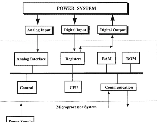
Figure 2.1 shows the functional block diagram of a digital computer based relay. The extensive
research effort in the field of digital relays and systems is worthwhile because the digital
technology has several advantages over the analogue technology.
1
Analog Input 1
Al
V
lalog Interface
i
i
[IJontroI
i
Power Supply
POWER SYSTEIM
1
Digital Input 1
,
1 .
Digital Output 1
•
I f
Registers
^
w
RAM
CPU
Microprocessor System
ROM
Communication
k
y
Chapter 2
Some of the advantages of digital technology is [36]:
1) The characteristics of digital components do not drift with temperature, supply voltage
changes or aging.
2) The performances of digital components do not change from part to part (as long as
numerical value, say 2 stored in memory remains 2 irrespective of where the number is
stored).
3) The equipment designs based on digital technology use fewer parts and connections.
4) The resolution of the solutions provided by digital devices depend on the number of
bits per word used in the arithmetic calculations.
5) The digital devices are not required to be tuned individually to obtain consistent results.
6) Most design changes can be made by changing the software only.
7) A digital device can perform both logic and arithmetic functions while controlling a
process.
8) The data recorded by a digital device is not corrupted except when an equipment failure
is experienced.
Properly designed microprocessor relays and systems are in several ways superior to the
electro-mechanical and solid-state relays and are being increasingly accepted for general use in
the utility industry. The benefits derived from the use of a microprocessor based relaying
Chapter 2
Economics
The bottom line in any technology is economics. Digital relays must cost less than (or at least
equal to) the cost of their electro-mechanical and solid-state counterparts [66]. The cost of the
electro-mechanical and solid-state relays has been increasing during the last twenty years
whereas the cost of digital devices has been decreasing rapidly during the same period. For
example, a personal computer system that is commercially sold for about $2,000 today, can
perform the tasks that $100,000 plus minicomputers were performing in the 1970's. It appears
that for several relay designs, the break even level has been reached.
It is important to appreciate that each digital relay has to use several non-digital components,
such as, a casing, plugs, switches, auxiliary transformers, power supplies, printed circuit
boards, etc. If the cost of those components is subtracted from the targeted price of a
microprocessor relay and allowance is made for packaging, marketing, recovery of
development costs, labor and profits, very small amounts may be available for the cost of
digital hardware to be used in a relay.
Performance
Properly designed digital relays perform at least as well as the presently available
electro-mechanical and solid-state relays. The performance in this context includes operating speed,
security and consistency. Certain operating features are improved by using digital processors
and without incorporating substantial design modifications. For example, memory action is
provided in a digital relay without a major design effort; a complex operating characteristic is
easily programmed in a digital relay.
Reliability
Digital equipment is perceived to fall more frequently than the components of the
electro-mechanical and solid-state relays. However, most digital relays are designed to monitor
themselves at regular intervals by executing the software in conjunction with pre-specified data
Chapter 2
of the results differing from the expected values, the microprocessor relay alerts an operator of
the equipment failure or impending failure. System reliability can be further increased by the
relay monitoring its peripherals. These features increase the reliability but, unfortunately,
increase the hardware and software costs also.
Flexibility
Digital processor relays are more flexible than the conventional relays. They include muhiple
characteristics and an option to select any one of those characteristics. This would ultimately
reduce the inventory required for repair and maintenance of relays as the presently used relays
are replaced by their digital counterparts. Another factor that affects flexibility is the possibility
of replacing the software of a digital relay and changing its entire nature. Because some inputs
to the relays in a substation are identical, a single transducer can provide an input to all digital
relays. It is also possible to design digital relays that can accept input from alternate devices in
case of the failure of a transducer. These features increase the hardware and software costs that
must be justified by the resulting improvements in system operation.
Background Tasks
The practice of collecting data at hv and ehv substations and providing to regional control
centers is quite common. Transmitting supervisory and maintenance alarms and their
descriptions has been in use for over twenty years. More recently, operational data, such as,
voltages, currents and power flow have been collected at dispersed locations in power systems
and transmitted to regional and central control centers. Since microprocessors handle the
communication functions with ease, several microprocessor based relays and systems are
designed to collect data and transmit it to a pre-specified location as a background task.
Another task that is performed by some microprocessor relays is the post-fault analysis of the
data collected during a fault. The relay computes the distance to a fault and provides the
information for use immediately if the fault is of a permanent nature and for fiiture use if it is
of a temporary nature. Most digital relays also collect sequence of events information locally,
Chapter 2 ^___
Byproducts
Like the solid state relays, the microprocessor relays present low burdens to current and
voltage transducers. Also, microprocessor relays use digitised data that can be received over
fibre optic links from electronic transducers installed at the hv and ehv levels. This approach
results in savings from cabling costs and high costs of presently used hv and ehv current and
voltage transformers. It will provide impetus for developing in the future unified systems of
transducers and protection systems.
Furthermore, the new approach to implement multi-protection schemes are based on a 32-bit
MC68020 microprocessor with its high speed, high computing power as well as its high level
language feature, provides special possibilities of implementing multi-protection schemes with
high accuracy and reliability. Some of these tasks are:
Multi-tasking digital relay protection (implementation of more than one relay based
single processor).
Multi-digital relaying techniques (overcurrent, differential protection).
Digital signal processing (power spectmm analysis, digital filtering).
Multi-processing capability, that is implementation of:
* adaptive protection scheme which improve the system performance;
Chapter 2
2.3 Digital Multi-function Protective Relay
2.3.1 Review of the Digital Multi-function Protective Relays
The availability of microprocessor at economic cost and it's high performance has allowed a
new concept of multi-function in the field of protection relays [6].
In recent years, various researchers are applymg concept of multi-function to protective relay.
Manzoul [37] described the implementation of several independent overcurrent relays using a
single microprocessor - the 8085. The implementation is based on the concept of multi-tasking
and time sharing in microprocessors. Each relay is implemented by a combination of a look-up
table and a counter. The software development and hardware testing are done using the
HP-64000 UX Microprocessor Development System. Harlow [38] applied a multi-function
protective relay to the cogeneration industry. His concept was to incorporate as many of the
required protection function as feasible into one package was proposed. The complete package
is thus seen to be versatile, compact and straight forward to user and utility. Gilany, Malik and
Hope [39] developed a new digital relaying technique for parallel transmission lines using a
single relay at each end. Only one relay at each end of the two lines is used. Yalla, [40]
described the development of a digital multi-function relay for the protection of the intertie
between a customer-owned generator and a utility system. The relay used state-of-the-art
digital signal processing techniques to measure the relay parameter, thereby eliminating
analogue hardware. The hardware design uses a dual microprocessor architecture to achieve
flexibility and high speed operation. Balasubramanian, and Oral [41] proposed a
microprocessor controlled general purpose programmable multi-function relay switching
system. The system is designed to switch independently multiple elecfronic appliances at
desired times and duration. Also, a switching control based on the day and night light
Chapter 2 _ _ _ _ _ _ _ _ _ ^
2.3.2 Benefits of Digital Multi-function Protective Relays
The present view is that the new approach to multi-function application is to use a single
microprocessor system and incorporate some of the protection function into one package. The
most important perceived benefits of multi-function protection are shown as follows:
• Using advanced digital electronic design to incorporate most (or all) of the required
protection reduces the expense [38]. A microprocessor based multi-function protective
relay hardware can be developed which can be characterised by the software held in its
system. Its standard hardware can be applied to a variety of protection relay functions
dependent on a variable software packages. It is envisaged that its application will be to
those relay functions that could not be justified because of the relatively low quantities
of required devices.
• The multi-fiinction protection relay can be specified by software greatly enhances the
flexibility in development and application.
• The multi-function digital relaying technology provides an economically viable
altemative for the protection. If the multi-function relays incorporate different
protection techniques, there is no increase in cost or complexity of protection to provide
the hybrid protection system equipment.
• Furthermore, the digital multi-fiinction protective relay has capability of providing
muhi-tasking, multi-digital relaying function with high reliability and open-end

![Figure 4.1 Time-current characteristics [66]](https://thumb-us.123doks.com/thumbv2/123dok_us/7934294.1317374/72.592.182.396.263.546/figure-time-current-characteristics.webp)