A masked ring-LWE implementation
?Oscar Reparaz, Sujoy Sinha Roy, Frederik Vercauteren, and Ingrid Verbauwhede
KU Leuven Dept. Electrical Engineering-ESAT/COSIC and iMinds Kasteelpark Arenberg 10, B-3001 Leuven-Heverlee, Belgium
Abstract. Lattice-based cryptography has been proposed as a postquan-tum public-key cryptosystem. In this paper, we present a masked ring-LWE decryption implementation resistant to first-order side-channel attacks. Our solution has the peculiarity that the entire computation is performed in the masked domain. This is achieved thanks to a new, bespoke masked decoder implementation. The output of the ring-LWE decryption are Boolean shares suitable for derivation of a symmetric key. We have implemented a hardware architecture of the masked ring-LWE processor on a Virtex-II FPGA, and have performed side channel analysis to confirm the soundness of our approach. The area of the protected architecture is around 2000 LUTs, a 20% increase with respect to the unprotected architecture. The protected implementation takes 7478 cy-cles to compute, which is only a factor×2.6 larger than the unprotected implementation.
1
Introduction
Once the quantum computer is built, Shor’s algorithm will make most current cryptographic algorithms obsolete. In particular, public-key cryptosystems that rely on number-theoretic hardness assumptions such as integer factorization (RSA) or discrete logarithms, either in Z∗p (Diffie-Hellman) or in elliptic curves
over finite fields, will be insecure. On the bright side, there is an entire branch of postquantum cryptography that is believed to resist mathematical attacks running on quantum computers.
There are three main branches of postquantum cryptosystems: based on codes, on multivariate quadratic equations or on lattices [1]. Lattice-based cryptographic constructions, founded on the learning with errors (LWE) problem [21] and its ring variant known as ring-LWE problem [15], have become a versatile tool for designing asymmetric encryption schemes [15], digital signatures [8] and homomorphic encryption schemes [9,3]. Several hardware and software implementations of such schemes have appeared in the literature. So far, the reported implementations have focused mainly on efficient implementation strategies, and very little research work has appeared in the area of side channel security of the lattice-based schemes.
?c
It comes as no surprise that implementations of postquantum algorithms are vulnerable to side-channel attacks. Side-channel attacks, as introduced by Kocher [13], exploit timing, power consumption or the electromagnetic emanation from a device executing a cryptographic implementation to extract secrets, such as cryptographic keys. A particularly powerful side-channel technique is Differential Power Analysis (DPA), introduced by Kocher et. al. [14]. In a typical DPA attack, the adversary measures the instantaneous power consumption of a device, places hypotheses on subkeys and applies statistical tests to confirm or reject the hypotheses. DPA attacks can be surprisingly easy to mount even with low-end equipment, and hence it is important to protect against them.
There are plenty of countermeasures against DPA. Most notably, masking [6,12] is both a provably sound and popular in industry. Masking effectively randomizes the computation of the cryptographic algorithm by splitting each intermediate into several shares, in such a way that each share is independent from any secret. This property is preserved through the entire computation. Thus, observing any single intermediate (for example, by a side-channel, be it known or unknown) reveals nothing about the secret. However, there are not many masking schemes specifically designed for postquantum cryptography. In [4] Brenner et. al. present a masked FPGA implementation of the post-quantum pseudo-random function SPRING.
In the rest of the paper, we focus on protecting the ring-LWE decryption operation against side-channel attacks with masking. The decryption algorithm is considerably exposed to DPA attacks since it repeatedly uses long-term private keys. In contrast, the encryption or key-generation procedures use ephemeral secrets only [24].
Our contribution. In this paper we present a very compact masked implementation of the ring-LWE decryption function. The masking countermeasure adds very limited overhead compared to other previous approaches, thanks to a bespoke probabilistic masked decoder designed specifically for our implementation. We implemented the design on a Virtex-II FPGA and tested the side-channel security with practical experiments that demonstrate the validity of our approach.
Organization. The paper is structured as follows: we provide a brief mathematical background of the ring-LWE encryption scheme in Section 2 and describe a high-level overview of the proposed masked ring-LWE decryption in Section 3. In the next section we construct the masked decoder and in Section 5 we show the experimental results. We analyze the error rates of the decryption operation in Section 6 and apply error correcting codes. We dedicate Section 7 for the side channel evaluation.
2
Preliminaries
Notation. The Latin lettersr,ciindicate polynomials. When we want to explicitly
is written asr∗c1. Coefficient-wise multiplication is denoted asr·c1. The letterm
denotes a string of bits, andqis an integer. Letters with primex0or double prime
x00 represent shares of variablex. Depending on the context, these shares are split either arithmeticallyx=x0+x00 (mod q) or Booleanx=x0+x00 (mod 2). A polynomialris shared into (r0, r00) by additively sharing each of its coefficients
r[i] such thatr=r0+r00.
Ring-LWE. For completeness, we give in this section a description of the three major algorithms of the ring-LWE public-key cryptosystem [15]: key-generation, encryption and decryption.
The ring-LWE encryption scheme works with polynomials in a ring Rq = Zq[x]/(f(x)), where f(x) is an irreducible polynomial of degree n. During the
key generation, encryption and decryption operations, polynomial arithmetic such as polynomial addition, subtraction and multiplication are performed. In addition, the key-generation and encryption operations require sampling of error polynomials from an error distribution (typically a discrete Gaussian.)
The ring-LWE encryption scheme is described in this way:
– In the key generation phase, two error polynomialsr1 andr2 are sampled from the discrete Gaussian distribution. The secret key is the polynomialr2
and the public key is the polynomialp=r1−g∗r2. After key generation, there is no use of the polynomialr1. The polynomialg is globally known. – In the encryption operation of a binary message vectormof lengthn, the
message is first lifted to a ring element ¯m∈Rq by multiplying the message
bits by q/2. The ciphertext is computed as a pair of polynomials (c1, c2) wherec1=g∗e1+e2andc2=p∗e1+e3+ ¯m∈Rq. The encryption operation
requires generation of three error polynomialse1,e2ande3.
– The decryption operation uses the private keyr2 to compute the message as
m= th(c1∗r2+c2). The decoding function th is a simple threshold decoder that is applied coefficient-wise and is defined as
th(x) =
0 ifx∈(0, q/4)∪(3q/4, q)
1 ifx∈(q/4,3q/4) (1)
Efficiency improvements. To achieve an efficient implementation of the encryption scheme, the irreducible polynomial f(x) is taken asxn+ 1 wherenis a power
of two, and the modulus q is chosen as a prime number satisfying q ≡ 1 mod 2n [18,25]. In this setting, polynomial multiplications can be efficiently performed inO(nlogn) time using the Number Theoretic Transform (NTT).
Following [25], we keep the ciphertext polynomials c1 and c2 in the NTT domain to reduce the computation cost of the decryption operation. The decryption operation thus computes the decrypted message as
m= th INTT(˜c1·˜r2+ ˜c2)
. (2)
performed coefficient-wise (as well as the addition ˜c1·r2˜ + ˜c2.) For convenience, we drop the tildes in the rest of the paper and work withc1,c2andr2in the NTT domain. We furthermore refer to ˜r2 simply asr. (We recall that the INTT is a linear transformation applied to thencoefficients ofa=r·c1+c2.) The decoding function th applies a threshold function to each coefficient of a as defined in Equation 1 to outputnrecovered message bits.
3
High-level overview
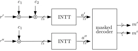
In this section, we give a high-level view of the masked ring-LWE implementation. The most natural way to split the computation of the decryption as Equation 2 is to split the secret polynomialradditively into two shares r0 andr00 such that
r[i] =r0[i] +r00[i] (modq) for alli. Thencoefficients ofr0 are chosen uniformly at random inZq in each execution of the decryption.
INTT
INTT
masked decoder r0
r00
m0
m00
c1 c2
c1
a0
a00
1 13
13
1 13
13
Fig. 1: General data flow of the masked ring-LWE decryption. r0 and r00 are the arithmetic shares of the private key r; c1 andc2 are the input unmasked ciphertext;m0 andm00are the Boolean shares of the recovered plaintext.
The bulk of the computation from Equation 2 is amenable to this splitting, since by linearity of the multiplication and INTT operation, we have that INTT(r·c2 +c1) = INTT(r0 ·c2+c1) + INTT(r00·c2). Thus, we can split almost the entire computation from Equation 2 into two branches, as drawn in Figure 1. The first branch computes onr0 to determine the polynomial
a0= INTT(r0·c2+c1) (3)
and the second branch operates onr00 to determine
a00= INTT(r00·c2). (4)
an existing ring-LWE processor for these operations, and leverage the numerous optimizations carried out for this block [18,25].
The final threshold th(·) operation of Equation 2 is obviously non-linear in the base field Fq, and hence cannot be independently applied to each branch
(Equation 3 and 4). There are generic approaches to mask arbitrary functions. For instance, in [4] an approach based on masked tables was used. However, these generic approaches are usually quite expensive in terms of area or randomness. In the following Section 4, we pursue another direction. We design a bespoke masked decoder that results in a very compact implementation.
4
Masked decoder
In this section we describe a very compact, probabilistic masked decoder. In the sequel,adenotes a single coefficient and (a0, a00) its shares such thata0+a00=a
(mod q). The decoder computes the function th(a) from the shares (a0, a00). We also drop the symbol (modq) when obvious.
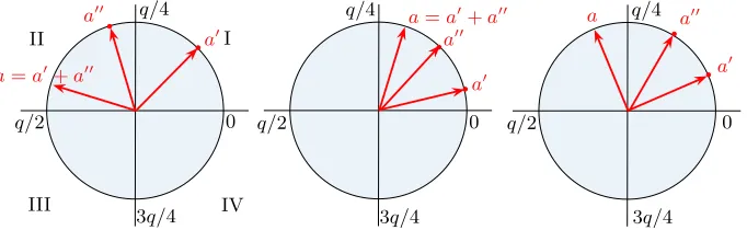
First crack. The key idea of the efficient masked decoder is that we do not need to know the exact values of the shares a0 anda00 of a coefficient ain order to compute th(a). For example, if 0< a0< q/4 andq/4< a00< q/2 thena=a0+a00
is bounded by q/4 < a < 3q/4, and thus th(a) = 1. That is, we learnt th(a) from only a few most significant bits froma0 anda00. We can use this idea to substantially simplify the complexity of the masked th function.
a a00
a0 q/4
3q/4
q/2 0
q/4
3q/4
q/2 0
I II
III IV
q/4
3q/4
q/2 0
a=a0+a00
a=a0+a00 a0
a0 a00
a00
Fig. 2: Idea for the masked decoder. Elements inZq are shown in a circle. Adding
two elements translates into adding their respective angles. Left: case 0< a0< q/4,
q/4< a00 < q/2, and therefore th(a) = 1. Center and right: case 0< a0 < q/4, 0< a00< q/4, which does not allow to infer th(a).
4.1 Rules
– If q/2 < a0 < 3q/4 and 3q/4 < a00 < q then q/4 < a < 3q/4 and thus th(a) = 1.
– Ifq/4< a0 < q/2 and q/2< a00<3q/4 then abelongs to (0, q/4)∪(3q/4, q) and thus th(a) = 0 (quadrants I and IV, left half of the circle).
– If 3q/4< a0< q and 0< a00< q/4 then abelongs to (0, q/4)∪(3q/4, q) and thus th(a) = 0.
There are 4 other rules that result from interchanginga0witha00 in the above expressions. (This follows straight from the symmetry of the additive splitting.) Essentially, with the only information of thequadrant of each sharea0 anda00 we can, in half of the cases, deduce the output of th(a). (For the explanation simplicity, we obviated what happens in the boundaries of the quadrant intervals. Similar conclusions hold when including them.)
What if no rule is hit? In roughly half of the cases, we can apply one of the 8 rules previously described to deduce the value of th(a). However, in the other half of the cases, none of the rules applies. A representative case of this event is shown in Figure 2, center and right. In both cases, 0< a0< q/4 and 0< a00< q/4. This situation is not covered by any of the 8 rules previously described. We see that in the center sub figure th(a) = 0 while in the right sub figure th(a) = 1, so in this case the quadrants of each sharea0 anda00 do not allow us to infer th(a).
The solution in this case is to refresh the splitting (a0, a00), that is, update
a0 ← a0 +∆1 and a00 ← a00 −∆1 for certain ∆1. (This refreshing naturally preserves the unshared valuea=a0+a00.) After the refreshing, the 8 rules can be checked again. If still no rule applies, the process is repeated with a different refreshing value∆i. Note that in each iteration of the step, roughly half of the
possible values of (a0, a00)∈
Zq×Zqare successfully decoded, and thus the amount
of pairs (a0, a00) that do not get decoded shrinks exponentially with the number of iterations. In our implementation, N= 16 iterations produces a satisfactory result. This will be studied in detail in Section 6.1.
Optimal cooked values for ∆i. One can determine a sequence of ∆i values
that maximizes the number of pairs successfully decoded after N iterations. We performed a first-order search for such a sequence of ∆i values. Each ∆i
maximizes the number of successfully decoded pairs afteri−1 iterations. For
q= 7681 the sequence of∆i shown in Appendix A was found.
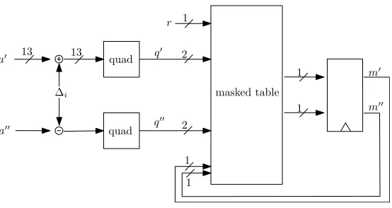
Architecture. The hardware architecture for the masked decoder follows from the previous working principle description. Our implementation is shown in Figure 3. From left to right, we see the first refreshing step by the constants
∆i. The constants∆i vary from iteration to iteration. After the refreshing step,
the quadrant function is applied to each share a0, a00. This quadrant function outputsxifabelongs to thex-th quadrant, and thus the output consists of 2 bits. These blocks are essentially 13-bit comparators, and thus relatively inexpensive in logic.1The subsequent rule checking on (q0, q00) is performed by a masked table
1
masked table quad
quad
2
∆i
a0
a00
13 13
r
2
1 1
1
1
1
m0
m00 q0
q00
Fig. 3: The masked decoder.
lookup that is described in the following section. The whole process is repeated
N = 16 iterations, and this number of iterations stays fixed even if the decoding is successful after the few first iterations.
4.2 Masked table lookup
The final step in the masked decoder is a masked table lookup. This table implements the rules described in Section 4.1, and essentially maps the output of each quadrantq0i andq00i (2 bits each) after thei-the iteration (i∈[1, N]) to
a (Boolean) masked output bit value (m0i, m00i). In our specific implementation,
we have other inputs: the result of the decoding from the previous iteration (m0
i−1, m00i−1) and an extra randomness bitr(fresh at each of theN iterations
for each of thencoefficients).
This is a well-studied problem that arises in other situations (for instance, when masking the sbox lookup in a typical block cipher) and there are plenty of approaches here to implement such masked table lookup. We opted for the approach of masked tables as in [26]. We set m0i ← r and we compute m00
i ←f(r, q0i, q00i, m0i−1, m00i−1). The functionf essentially bypasses the previous
decoded value when no rule applies to q0
i, q00i by setting the output m00i to r+m0
i−1+m00i−1 (refreshing the content of the output registers). If a rule
applies toq0
i, qi00, it sets the outputm00i accordingly. By doing this, we can register
always the output of this table and no control logic to enable such output register is needed (it is implicitly integrated into this masked table.) This is the reason why the table sees also the previous decoded valuem0
i−1 andm00i−1.
The usual precautions are applied when implementing f. For our target FPGA platform, we carefully split the 7-bit input to 1-bit output function f
When implemented in an ASIC, it may be preferable to store this masked table in ROM (since the contents of the table are immutable and the size is small.)
The output of this table is (Boolean) masked, and thus no unmasked value lives within the implementation. This is suited for consumption of a masked AES module (say) after some preprocessing as will be detailed later. We stress that we use masked tables on theoutput of the quadrants. This is the key for our reduced area requirements, as will be explained in the next Section 5.
5
Implementation results
We implemented the fully masked ring-LWE decryption system with the parameter set (n, q, s) = (256,7681,11.32) first introduced in [11], corresponding to a medium-term security level. The target platform is a Xilinx Virtex-II xc2vp7 FPGA. The HDL files were synthesized within Xilinx ISE v8.2 with optimization settings set to balanced andKEEP HIERARCHYflag when appropriate to prevent optimization of security-critical components. We base our arithmetic processor on the design from [25].
5.1 Area
In our case, a single arithmetic coprocessor performs serially the computations of Equation 3 and then that of Equation 4. This incurs in a very slight area overhead (only the control microcode is slightly modified, plus the masked decoder), at the obvious cost of an increased execution time. In comparison to the unprotected version, our protected decryption scheme consumes more memory as now we store two sharesr0 andr00 of the secret polynomialr, and the two output polynomials
a0 anda00 from the two INTT operations.
In Table 1, we can see that the proposed masking of the ring-LWE architecture incurs an additional area overhead of only 301 LUTs and 129 FFs in comparison to the unprotected version. This additional area cost is mostly due to a pair of masked decoders. Due to its low area overhead, we chose to keep two masked decoders in parallel, decoding two coefficients simultaneously. (This nicely fits with the memory organization of the arithmetic coprocessor, since it fits two 13-bit coefficients in each memory word.) Thus, we use two addition and subtraction circuits for the refreshing with∆i (accounting for 160 LUTs) and two masked
tables (90 LUTs in total.)
We note that we could straightforward reduce the additional area cost by reusing the 13-bit addition and subtraction circuits present in the arithmetic coprocessor. Since during a decoding operation, the arithmetic coprocessor remains idle, reusing of the addition and subtraction circuits do not cause any increase in the cycle count. For simplicity, we did not implement this approach.
5.2 Cycle count
Implementation LUTs/FFs/DSPs Freq Cycles/Time(µs)
Algorithm (MHz) Decryption
Unprotected RLWE 1713/830/1 120 2.8k/23.5
Protected RLWE 2014/959/1 100 7.5k/75.2
Table 1: Performance and Comparison on Xilinx Virtex-II xc2vp7 FPGA. Note that these results are not directly comparable with [25], since the latter were obtained from a more advanced Virtex-6 FPGA, which has 6-bit input LUTs and superior routing mechanisms in comparison to our target FPGA.
unprotected ring-LWE decryption), Equation 4 takes 2590 cycles, slightly less than Equation 3 since there is no addition present in the second branch.
The two-way parallel masked decoder takes 12×n×N+cycles to decode all the coefficients into message bits. In our case withn= 256,N = 16 the masked decoder takes 2048 cycles. Thus in total, a masked decryption operation requires 7478 cycles. The arithmetic coprocessor and the masked decoder run in constant time and constant flow.
5.3 Comparison with an elliptic-curve cryptosystem
We compare our protected decryption scheme with the unprotected high-speed elliptic curve scalar multiplier architecture proposed by Rebeiro et al. in [20]. The architecture for the field GF(2233) consumes 23 147 LUTs and computes an
unprotected scalar multiplication in 12.5µs on a more advanced Virtex-4 FPGA. Thus the scalar multiplier has an area×time product of approximately 289 337. Our protected ring-LWE decryption (for a similar security) achieves an area× time product of approximately 151 452 on a Virtex-2 FPGA; thus achieving at least 1.9 times better figure of merit.
5.4 Trade-offs
not reuse the arithmetic circuitry of the arithmetic coprocessor for the refreshing operation of the masked decoder.
5.5 Maximum frequency
We note that the arithmetic coprocessor is a very optimized unit with a complex pipeline organization. We thus insert two pipeline stages in the masked decoder to match the maximum frequency of the whole system to that of the arithmetic coprocessor. In this way, the design can run up to almost 100 MHz. The critical path is inside the arithmetic multiplier.
6
Discussion
6.1 Error rates
Cryptosystems based on ring-LWE are inherently probabilistic. This means that there is a non-zero probability that the recovered plaintext after ring-LWE decryption is not exactly the plaintext before encryption. In our case, due to the probabilistic nature of our masked decoder approach, there is a second source of noise. Since the number of iterations of the masked decoder is finite, there are some pair values (a0, a00) that will not get decoded within the fixed finite number of iterations. In this section, we first explain the error rate of the probabilistic decoding in isolation, and then we switch to the global system error rate and point out strategies to mitigate it.
Errors due to the probabilistic decoding. In this section, we assume that the plaintext bit is 1 and the unmasked inputato the masked decoder is in (q/4,3q/4). The additional error due to the probabilistic masked decoder is the probability
pethat (a0, a00) does not get successfully decoded. Let us writeps= 1−pe.
This probabilitypsis influenced by two distributions. We have that
ps= X
Pr[successful decode|a]·Pr[a] (5)
where the sum is taken over a ∈ (q/4,3q/4). On the one hand, Pr[successful decode|a] is the probability that the decoder successfully decodes
a. On the other, Pr[a] is the probability with whicha takes various values in (q/4,3q/4).
The distribution of the decoder success probability Pr[successful decode|a] as a function of the unshared input value a to the decoder can be easily computed by averaging over all possible pairs (a0, a00) such that a0 +a00 =
a. Since for any given value of a, its shares a0 or a00 are (individually) equiprobable, we compute Pr[successful decode|a] as Pr[successful decode|a] =
1 q
P
a0+a00=aPr[successful decode of (a0, a00)].
0 q/4 q/2 3q/4 q 0
0.2 0.4 0.6 0.8 1
unshared input to decoder
p successful decoding
N=16 N=2
0 q/4 q/2 3q/4 q
0 0.2 0.4 0.6 0.8
1x 10 −3
input to the decoding
p appeareance
Fig. 4: Left: empirical success distribution for the masked decoder. Right: Distribution ofawhen plaintext is 1.
get decoded correctly. Only when the input valueaapproachesq/4 or 3q/4, the performance degrades. When using a larger number of iterationsN = 16 this effect is less pronounced when compared toN = 2 iterations, as Figure 4 shows.
On the other hand, it is easy to see that not all unshared inputsa to the decoder are equally likely. By the construction of the ring-LWE decryption function, the unshared input to the decoder a is either centered around q/2 (resp. 0) when the message bit is 1 (resp. 0). This distribution Pr[a] is plotted in
Figure 4, right.
These two observations combined produce a nice interaction between the prior distribution Pr[a] of a (given by the ring-LWE decryption) and the success distribution of the masked decoder Pr[successful decode|a] as in Equation 5. Namely, values of a that are difficult to decode (those with low Pr[successful decode|a]) are quite unlikely to appear as input to the masked decoder (their Pr[a] is also low). This positive interaction keeps the global error rate of the system quite low. This is precisely quantified in the next paragraph.
Global error rate and number of iterations. We performed simulations to estimate the global error rate and determine the required number of iterationsN in our design. Over 106bits, the average error per bit using a deterministic decoder was pbaseline = 3.634375×10⁻⁵. This is a baseline error intrinsic to the ring-LWE
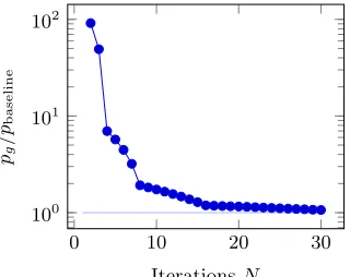
construction. When we plug in the probabilistic decoder, the global, end-to-end, error rate per bit pg increases. (We havepg = pbaseline+pe.) In Figure 5, we
can find the global error rate for different values of the number of iterationsN
of the decoding. At N = 3, for instance, the error rate is pg = 1.7844×10⁻³,
Iterationspg [×10−5]pg/pbaseline
N=2 332.24 91.41
3 178.44 49.09
4 25.36 6.97
5 20.77 5.71
6 16.22 4.46
8 6.97 1.91
16 4.32 1.19
24 4.06 1.11
30 3.87 1.06
Fig. 5: Global error rates with the probabilistic decoder.
0 10 20 30
100 101
102
IterationsN pg
/p
baseline
Fig. 6: Evolution of the ratiopg/pbaseline
as the number of iterationsN grows.
the global error rate is quite low, adding less than 20% to the intrinsic error rate when compared to a deterministic decoder, as it can be see in Figure 5.
6.2 Comparison with other decoding strategies
We are only aware of a similar masked decoder, the one presented in [4]. There the authors resort to a generic masking method, namely masked tables, to perform the decoding. Translating the ideas of [4] in our context, we would need two tables of 213bits (one of them random). For a smaller group
Zd withd= 257
the authors report an utilization of 1331 slices on a Virtex 6 FPGA. While the results in slices are not directly comparable with ours, we point out that the size of the masked table following the approach of [4] grows linearly in the group size
q, while for our solution the size of the masked table stays constant (independent ofq), and the quadrant blocks grow only logarithmically in q. The cycle count, however, is larger in our solution. The critical observation of our masked decoder is that we cancompress the input coefficient shares a0 anda00to a mere two bit per share (the output of each quadrant) and then perform the decoding based on the information of the two quadrants (4 bits.)
6.3 Post-processing
Albeit the computation from Equation (2) is commonly referred as the “ring-LWE decryption”, the decryption process should include a post-processing on the recovered messagem. This post-processing consists of error correction and padding verification.
composite is ring-LWE encrypted. The output of the ring-LWE decryption should be corrected for errors, preferably in the masked domain. For syndrome decoding of linear codes, this can easily be done by masking the syndrome table.
Padding schemes. As presented, the ring-LWE system is malleable. CCA security can be achieved with a padding mechanism. The Fujisaki-Okamoto [10] padding scheme is known to work with ring-LWE [17]. This padding scheme makes use of standard symmetric cryptographic constructions whose masked implementations are well studied. We point out that key-encapsulation mechanisms may result in a more compact and simpler implementation.
6.4 Extension to higher-order security
We point out that the approach laid out in Section 3 scales quite well with the security order. To achieve security at level d+ 1, one would need to split the computation of Equation 2 intodbranches analogously to Equation 3. The masked decoder can follow the same principles with the appropriate modifications. The complexity of this decoder obviously grows. Generic approaches to perform this computation have been discussed in [7,2,22].
7
Evaluation
For the purposes of a side-channel evaluation, we implemented the full design on a SASEBO G board. The design was clocked at 18.75 MHz and the power consumption was sampled at 500 MS/s. This platform is very low noise.
We provide a very advantageous setting for the adversary: we assume that the evaluator knows the details about the implementation (for example, pipeline stages). In addition, we assume that while guessing a subkey, the adversary knows the rest of the key. These assumptions allow to comfortably place predictions on intermediates arbitrarily deep into the computation. While this may represent a very powerful attacker and somewhat unrealistic, the algebraic structure of such cryptosystem may help the attacker to predict deep intermediates with relatively low effort. We refer the reader to the extended version of this paper for an attack on half-masked ring-LWE decryption that uses these ideas. This stresses the necessity of masking the decoding function entirely.
The evaluation methodology to test if the masking is sound is as follows. We first proceed with first-order key-recovery attacks when the randomness source (PRNG) is switched off. We demonstrate that in that situation the attacks are successful, indicating that the setup and procedure is sound. Then we switch on the PRNG and repeat the attacks. If the masking is sound, the first-order attacks shall not succeed. In addition, we perform second-order attacks to confirm that the previous first-order analyses were carried out with enough traces.
bit. We modeled the power consumption of a register as the Hamming distance between two consecutive values held in the register, and used Pearson’s correlation coefficient to compare predictions with measurements [5].
1000 2000 3000 4000 5000 6000 7000
time in cycles
sample
ρ
mean
curv
e
ρ= 0.27, intermediate:a0[0]
ρ= 0.21, intermediate:m0[0]
ρ= 0.3, intermediate:r00[0]·c1[0]
ρ= 0.25, intermediate:r0[0]·c1[0] +c2[0]
branch 1 branch 2 decoding
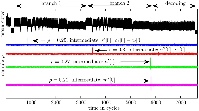
Fig. 7: PRNG off. On top, black, one power consumption trace. The different computational stages can be distinguished: first branch, second branch and decoding. Next, in blue, the correlation trace for the valuer0[0]·c1[0] +c2[0]. The correlation achieves a maximum value ofρ= 0.25. Below, in red, correlation for
r00·c1 (maxρ≈0.3); in green: correlation for the input of the masked decoder
a0[0]. At the bottom: correlation with one message bitm0[0].
7.1 PRNG off
We first begin the experiments when the PRNG is off. That is, the sharing of
r intor0 andr00 on each execution is deterministic. This would not happen in practice, as an active PRNG would randomize the representation ofr in each execution. In our setting, this would mean that the masking is switched off.
0 2000 4000 6000 8000 10000 −0.5
0 0.5
number of traces
sample correlation
0 2000 4000 6000 8000 10000 −0.5
0 0.5
number of traces
sample correlation
Fig. 8: PRNG off. Evolution of the correlation coefficient as the number of traces increases for the intermediatesr0[0]·c1[0] +c2[0] (left) and r00[0]·c1[0] (right). Correct subkey guess in red, all other guesses in green. A 99.99 % confidence interval forρ= 0 is plotted in black discontinuous line. We can see that starting from hundred measurements the attacks are successful.
7.2 PRNG on
0 2000 4000 6000 8000 10000 −0.5
0 0.5
number of traces
sample correlation
0 2000 4000 6000 8000 10000 −0.5
0 0.5
number of traces
sample correlation
Fig. 9: Analogous to Figure 8, but with PRNG on. The correct subkey is no longer identifiable. This is expected and means that the masking is effective.
7.3 Second-order attacks
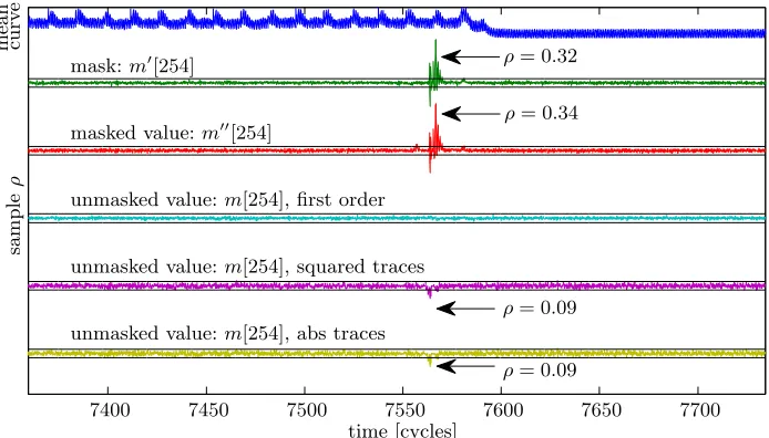
To confirm that we used enough traces in our previous analyses, we perform here second-order attacks on the masked implementation with the PRNG on. We will focus on the masked decoder. In Figure 10 we draw on top a mean curve in the region of 7 400 to 7 700 cycles, corresponding to the end of the masked decoding. We target one output bit of the decoding:m[254].
7400 7450 7500 7550 7600 7650 7700
sample
ρ
mask:m0[254]
masked value:m00[254]
unmasked value:m[254], first order
unmasked value:m[254], squared traces
unmasked value:m[254], abs traces
curv
e
mean
time [cycles]
ρ= 0.34
ρ= 0.32
ρ= 0.09
ρ= 0.09
Fig. 10: Correlation traces for intermediates within the shared decoder. On top, a power measurement trace showing the last 15 decodings. Below, correlation traces. The first two (masks and masked values) assume that the adversary knows the masks. The third one, in light blue, is a first-order attack without knowing the attack, and is unsuccessful. In contrast, the second-order attack against the same intermediate is successful, as the traces in magenta and yellow show.
0 0.5 1 1.5 2
x 104 −0.5
0 0.5
number of traces
sample correlation
0 0.5 1 1.5 2
x 104 −0.5
0 0.5
number of traces
sample correlation
Fig. 11: Left: correlation as the number of traces increases for the first-order attack (PRNG on), around clock cycle 7560. Right: correlation for the second-order attack with masks on. The attack begins to be successful with 2 000 measurements.
In Figure 11 we can see the evolution as a function of the number of traces. We can see that starting from ≈2000 measurements this second-order attack is successful. This confirms that the first-order attacks of Section 7.2 were carried out with enough traces, since a second-order attack is already successful starting from≈2000 measurements.
We remark that the relatively low number of traces required for the second-order attack is due to the very friendly scenario for the evaluator. The platform is low noise and no other countermeasure except than masking was implemented. In practice, masking needs a source of noise to be effective, and consequently the higher-order attacks would be harder to mount, requiring more traces [6] and more computation [23].
7.4 Horizontal DPA attacks
During the decoder operation, the input coefficients are refreshedN−1 = 15 times with publicly known offsets∆i. The device thus handles consecutively the
valuesa0, a0+∆1, ...,a0+∆1+. . .+∆15. This may enable a horizontal DPA attack [16] during the operation: the adversary may collect a single trace, split it into 16 chunks and then perform a DPA on these 16 chunks to recover the mask a0. Once the masks from all traces are discovered, a first-order, vertical DPA applies.
Fig. 12: Crosscorrelation trace. The x and y axes represent time, flowing from the upper left hand side corner to the lower right. The entire figure spans 7500 cycles (as Figure 7). It is possible to distinguish the two branch computations (including
its components) and the decoding. Colors enhanced to improve contrast.
∆i. This randomizes the order of execution of each refreshing with∆i, and thus
the exposure to horizontal DPA attacks is minimized.
8
Conclusion
In this paper we described a practical side-channel protected implementation of the lattice-based ring-LWE asymmetric decryption. Our solution is based on the sound principles of masking and incurs in a manageable overhead (in cycles and area). A key component of our solution is a bespoke masked decoder. Our implementation performs the entire ring-LWE decryption computation in the masked domain.
References
1. Daniel J. Bernstein, Johannes Buchmann, and Erik Dahmen. Post Quantum Cryptography. Springer, 1st edition, 2008.
2. Beg¨ul Bilgin, Benedikt Gierlichs, Svetla Nikova, Ventzislav Nikov, and Vincent Rijmen. Higher-order threshold implementations. InASIACRYPT, volume 8874 of LNCS, pages 326–343. Springer, 2014.
3. Joppe W. Bos, Kristin Lauter, Jake Loftus, and Michael Naehrig. Improved security for a ring-based fully homomorphic encryption scheme. InCryptography and Coding, volume 8308 ofLNCS, pages 45–64. Springer, 2013.
4. Hai Brenner, Lubos Gaspar, Ga¨etan Leurent, Alon Rosen, and Fran¸cois-Xavier Standaert. FPGA implementations of SPRING - and their countermeasures against side-channel attacks. In CHES, volume 8731 ofLNCS, pages 414–432. Springer, 2014.
5. Eric Brier, Christophe Clavier, and Francis Olivier. Correlation power analysis with a leakage model. InCHES, volume 3156 ofLNCS, pages 16–29. Springer, 2004. 6. Suresh Chari, Charanjit S. Jutla, Josyula R. Rao, and Pankaj Rohatgi. Towards
sound approaches to counteract power-analysis attacks. InCRYPTO, volume 1666 ofLNCS, pages 398–412. Springer, 1999.
7. Jean-S´ebastien Coron. Higher order masking of look-up tables. InEUROCRYPT, volume 8441 ofLNCS, pages 441–458. Springer, 2014.
8. L´eo Ducas, Alain Durmus, Tancr´ede Lepoint, and Vadim Lyubashevsky. Lattice signatures and bimodal gaussians. InCRYPTO, volume 8042 ofLNCS, pages 40–56. Springer, 2013.
9. Junfeng Fan and Frederik Vercauteren. Somewhat practical fully homomorphic encryption. Cryptology ePrint Archive, Report 2012/144, 2012. http://eprint. iacr.org/.
10. Eiichiro Fujisaki and Tatsuaki Okamoto. Secure integration of asymmetric and symmetric encryption schemes. Journal of Cryptology, 26(1):80–101, 2013. 11. Norman G¨ottert, Thomas Feller, Michael Schneider, Johannes Buchmann, and
Sorin Huss. On the design of hardware building blocks for modern lattice-based encryption schemes. InCHES, volume 7428 ofLNCS, pages 512–529. Springer, 2012.
12. Louis Goubin and Jacques Patarin. DES and differential power analysis the duplication method. In CHES, volume 1717 ofLNCS, pages 158–172. Springer, 1999.
13. Paul Kocher. Timing attacks on implementations of Diffie-Hellman, RSA, DSS, and other systems. InCRYPTO, volume 1109 ofLNCS, pages 104–113. Springer, 1996.
14. Paul Kocher, Joshua Jaffe, and Benjamin Jun. Differential power analysis. In CRYPTO, volume 1666 ofLNCS, pages 388–397. Springer, 1999.
15. Vadim Lyubashevsky, Chris Peikert, and Oded Regev. On ideal lattices and learning with errors over rings. In EUROCRYPT, volume 6110 ofLNCS, pages 1–23. Springer, 2010. Full Version available at Cryptology ePrint Archive, Report 2012/230.
16. J. Pan, J.I. den Hartog, and Jiqiang Lu. You cannot hide behind the mask: Power analysis on a provably secure s-box implementation. In Information Security Applications, volume 5932 ofLNCS, pages 178–192. Springer, 2009.
18. Thomas P¨oppelmann and Tim G¨uneysu. Towards practical lattice-based public-key encryption on reconfigurable hardware. InSelected Areas in Cryptography – SAC 2013, volume 8282 ofLNCS, pages 68–85. Springer, 2014.
19. E. Prouff, M. Rivain, and R. Bevan. Statistical analysis of second order differential power analysis. Computers, IEEE Transactions on, 58(6):799–811, June 2009. 20. Chester Rebeiro, Sujoy Sinha Roy, and Debdeep Mukhopadhyay. Pushing the
limits of high-speed GF(2m) elliptic curve scalar multiplication on fpgas. InCHES,
volume 7428 ofLNCS, pages 494–511. Springer, 2012.
21. Oded Regev. On lattices, learning with errors, random linear codes, and cryptography. In Proceedings of the Thirty-seventh Annual ACM Symposium on Theory of Computing, STOC ’05, pages 84–93, New York, NY, USA, 2005. ACM.
22. Oscar Reparaz, Beg¨ul Bilgin, Svetla Nikova, Benedikt Gierlichs, and Ingrid Verbauwhede. Consolidating masking schemes. In CRYPTO, volume 9215 of LNCS, pages 1–20. Springer, 2015.
23. Oscar Reparaz, Benedikt Gierlichs, and Ingrid Verbauwhede. Selecting time samples for multivariate DPA attacks. InCHES, volume 7428 of LNCS, pages 155–174. Springer, 2012.
24. Sujoy Sinha Roy, Oscar Reparaz, Frederik Vercauteren, and Ingrid Verbauwhede. Compact and side channel secure discrete gaussian sampling. IACR Cryptology ePrint Archive, 2014:591, 2014.
25. Sujoy Sinha Roy, Frederik Vercauteren, Nele Mentens, Donald Donglong Chen, and Ingrid Verbauwhede. Compact ring-lwe cryptoprocessor. InCHES, volume 8731 of LNCS, pages 371–391. Springer, 2014.
26. E.V. Trichina. Table lookup operation on masked data, 2013. US Patent 8,422,668. 27. Michael Tunstall, Neil Hanley, Robert P McEvoy, Claire Whelan, Colin C Murphy, and William P Marnane. Correlation power analysis of large word sizes. IET Irish Signals and Systems Conference (ISSC) 2007, September 2007. Available at http://www.cs.bris.ac.uk/home/tunstall/papers/THMWMM.pdf.
A
Optimal values of
∆
ifor
q
= 7681
∆(i) = (960,1440,480,1680,240,720,1200,1800, (6) 120,360,600,840,1080,1320,1560,1860, (7) 60,180,300,420,540,660,780,900,1020, (8) 1140,1260,1380,1500,1620,1740,1890, (9) 30,90,150,210,270,330,390,450,510, (10) 570,630,690,750,810,870,930,990,1050, (11)
1110,1170,1230) (12)
These values were found by exhaustive first-order search. The value∆i is
B
Attack on half-masked variant
In this section, we analyze the security of a masked ring-LWE variant where the intermediates just before decoding are unmasked, and the decoding is performed in the unmasked domain. This alternative is definitely cheaper than full masking. In the following, we provide evidence to show that this clearly does not provide enough security in our case.
(A seemingly similar situation appears in [4]. However, there are important differences—namely it is not possible to choose ciphertexts. In the following, we are not analyzing the variant of [4] but only the half-masked ring-LWE.)
A common argument is that after key-diffusion is complete, prediction of the intermediates is not possible and hence standard DPA attacks to the half-masked ring-LWE do not apply. We will see that this is not strictly true, if the attacker can choose ciphertexts.
Assume that the coefficients of the polynomiala= INTT(r·c1+c2) appear unmasked in the implementation. Let the adversary collect measurements with chosen ciphertext. The ciphertextc1has the following structure: all the coefficients fixed exceptc1[0] randomly varying. The ciphertextc2has the same structure. Then observe that due to linearity of the INTT operation,a[0] can be written as
a[0] =α(r[0]·c1[0] +c2[0]) +β, where
– αis a public constant determined by the INTT transformation.
– βis a secret constant that is a function of the other (unknown) key coefficients
r[1], . . . , r[255]. Note that by construction β is constant within the set of collected traces.
Thus, an attacker can perform a DPA attack targeting the intermediatea[0] and placing predictions on (r[0], β). The adversary recoversr[0] and proceeds to recover other key coefficients. We have verified this attack in simulations, even when using th(a[i]) as intermediate.
(It may seem that the high number of hypotheses, 226 may produce a cumbersome attack. However, one can apply techniques of partial correlation [5] to alleviate the computational effort of DPA on large word sizes [27]. And we have experimented that in practice it makes sense to first recoverr[0] (this is easier due to larger non-linearity of the modular multiplication) and thenβ(which may be harder due to the low non-linearity of the modular addition), splitting the 226
![Table 1: Performance and Comparison on Xilinx Virtex-II xc2vp7 FPGA. Notethat these results are not directly comparable with [25], since the latter wereobtained from a more advanced Virtex-6 FPGA, which has 6-bit input LUTsand superior routing mechanisms in comparison to our target FPGA.](https://thumb-us.123doks.com/thumbv2/123dok_us/7929030.1316577/9.612.187.428.116.157/performance-comparison-notethat-comparable-wereobtained-advanced-mechanisms-comparison.webp)

![Fig. 8: PRNG off. Evolution of the correlation coefficient as the number of tracesincreases for the intermediates r′[0] · c1[0] + c2[0] (left) and r′′[0] · c1[0] (right).Correct subkey guess in red, all other guesses in green](https://thumb-us.123doks.com/thumbv2/123dok_us/7929030.1316577/15.612.166.447.402.532/evolution-correlation-coecient-number-tracesincreases-intermediates-correct-guesses.webp)