Miniaturizing Components by Reverse
Engineering and Rapid Prototyping
Techniques
L. Francis Xavier
1, Dr. D. Elangovan
2, N.Subramani
3, R.Mahesh
4Assistant Professor, Department of Mechanical Engineering, Karpagam College of Engineering, Coimbatore,
Tamilnadu, India1
Lecturer, Department of Mechanical Engineering, Karpagam College of Engineering, Coimbatore, Tamilnadu, India3&4
Professor and Head of the Department of Mechanical Engineering, Karpagam College of Engineering, Coimbatore,
Tamilnadu, India2
ABSTRACT: Miniaturization plays a vital role in today’s modern world. Recent manufacturing trends are focused at manufacturing components in compact size. Nowadays, the size of the product are getting smaller and smaller to reduce its weight, compact in size, less power consumption, less space utilization etc. The paper aims at proposing an idea to create miniaturized components by reverse engineering and rapid prototyping techniques. Rapid prototyping is techniques used to quickly fabricate prototype or a model of a physical part using three dimensional (3D) computer aided design and reverse engineering process involves collecting the dimensions of an component from the model. In this work, the skeleton of the 3D model of the cooling fan casing is collected using Micro scribe – Reverse Engineering probe. Rhinoceros software was used to alter the dimensions in the created model. Finally, the model is imported into the UP – RPT software and the 3D model are sliced into many layers and the model is developed by fused deposition method in the RPT machine.
KEYWORDS:reverse engineering, rapid prototyping, Computer-Aided Design, 3D geometrical model.
I. INTRODUCTION
Rapid prototyping and Reverse engineering can be utilized together to make manufacturing simple by reducing product development time and cost. 3D scanning is used to convert the real life components into CAD model by capturing up to 19,000 points per second [1]. Thus it is effective and highly accurate. Design changes in the CAD model can be done if necessary. Thus the component is redesigned by scaling it into a compact model.
Physical model that directly represents the component is much better than pure computer visualization. A real component helps in obtaining the necessary information for manufacturing information
generation. Rapid prototyping is a means through which the product geometry is directly utilized to get the physical shape of the component [1].
The word “Rapid” in RP is a relative term. The rapid actually refers to the reduced time from initial design to the production of the final part. This is due to the elimination of extensive amounts of hand and machine work involved in making prototypes with traditional methods, as well as the ability to quickly iterate and test a design through various stages. Also, as contrasted with more complicated CAM programming and CNC machining, RP software and machines are generally simple and quick to use, resulting in significantly reduced “human time” needed to produce prototype parts. [5]
RPT is used in various applications like biomedical modeling, jewelry design, aerospace, automobile and general engineering field.
Copyright to IJIRSET www.ijirset.com 1833 A 3D scanner is a device that analyses a real world object or environment to on its shape and possibly its appearance. The collected data can then be used to construct digital three dimensional models. There are a variety of technologies for digitally acquiring the shape of a 3D object. A well-established classification divides them into two types
a. Contact 3D scanners and b.Non-contact 3D scanners.
There are a variety of technologies that fall under each of these categories [3].
In this work, we have planned to prepare a miniaturized cooling fan set up using reverse engineering and Rapid prototyping concepts.
II. PROPOSEDMETHODOLOGY
Although several rapid prototyping techniques exist, all employ the same basic five-step process [4]. The steps are:
1. Create a CAD model of the design 2. Convert the CAD model to STL format
3. Slice the STL file into thin cross-sectional layers 4. Construct the model one layer atop another 5. Clean and finish the model
The basic methodology for all current rapid prototyping techniques can be summarized as follows:
A CAD model is constructed, and then converted to STL format. The resolution can be set to minimize stair stepping. The RP machine processes the STL file by creating sliced layers of the model. The first layer of the physical model is created. The model is then lowered by the thickness of the next layer, and the process is repeated until completion of the model.[5]
2.1 CAD Model Creation:
First, the object to be built is modeled using a Computer-Aided Design (CAD) software package. Solid modelers, such as Pro/ENGINEER, tend to represent 3-D objects more accurately than wire-frame modelers such as AutoCAD, and will therefore yield better results. The designer can use a pre-existing CAD file or may wish to create one expressly for prototyping purposes. This process is identical for all of the RP build techniques.
2.2 Conversion to STL Format:
The various CAD packages use a number of different algorithms to represent solid objects. To establish consistency, the STL (stereo-lithography, the first RP technique) format has been adopted as the standard of the rapid prototyping industry. The second step, therefore, is to convert the CAD file into STL format. STL files use planar elements, they cannot represent curved surfaces exactly.
Increasing the number of triangles improves the approximation, but at the cost of bigger files size. Large, complicated files require more time to preprocess and build, so the designer must balance accuracy with manageability to produce a useful STL file. Since the stl format is universal, this process is identical for all of the RP build techniques.
2.3Slicing of the 3D model into many layers:
In the third step, a pre-processing program prepares the STL file to be built. Several programs are available, and most allow the user to adjust the size, location and orientation of the model. The pre-processing software slices the STL model into a number of layers from 0.01 mm to 0.7 mm thick, depending on the build technique. The program may also generate an auxiliary structure to support the model during the build. Supports are useful for delicate features such as overhangs, internal cavities, and thin-walled sections. Each PR machine manufacturer supplies their own proprietary preprocessing software [5].
2.4 Layer by Layer Construction:
2.5 Clean and Finish:
The final step is post-processing. This involves removing the prototype from the machine and detaching any supports[1]. Some photosensitive materials need to be fully cured before use. Prototypes may also require minor cleaning and surface treatment. Sanding, sealing, and or painting the model will improve its appearance and durability.
III. FINISHING PROCESSES
The finishing process involves the following steps if needed. Cutting,
milling, Lathe,
Sand blasting Coating Polishing Painting Boring, grinding etc.
IV. EXPERIMENTALSETUP
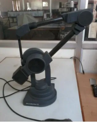
4.1 Micro Scribe G
By using the probe in micro scribe G with 5 degrees of freedom, the boundary or the skeleton points of the object is collected.
FIG 4.1 Micro scribe G
Rhinoceros software was used to cover the skeleton of the drawing by skin of surfaces.Finaly the drawing was converted to a solid model. By importing the created model into UP software (RPT software),The model was sliced to small layers and was added layer by layer.
Copyright to IJIRSET www.ijirset.com 1835 Fig. 4.2 FDM 3D Printing
4.2 Fused Deposition Modeling
In this technique, filaments of heated thermoplastic are extruded from a tip that moves in the x-y plane. Like a baker decorating a cake, the controlled extrusion head deposits very thin beads of material onto the build platform to form the first layer. The platform is maintained at a lower temperature, so that the thermoplastic quickly hardens. After the platform lowers, the extrusion head deposits a second layer upon the first layer.
The build material is usually supplied in filament form with 0.8mm diameter, but the layer thickness and vertical dimensional accuracy is determined by the extrusion nozzle diameter and the rate of feeding of the building material, which ranges from 0.018 to 0.008 inches.in x-y plane, 0.001 inch resolution is achievable. Thermo static material is most often used which including Acrylonitrate Butadiene Styrene (ABS).
4.3 PROCESS OF MAKING MINIATURIZED COMPONENTS
Initially the probe is used for collecting data of the component and imports the component cad model in the Rhinoceros software to edit any preference change in parent component. Then it will be scaling down the diagram to our desired dimension. Then the collected data is send to the rpt machine 3D printer. After sending a command by manual, it will be starts working. Initially it takes a few minute for heating purpose at the same time ABS wire is feed by additional source in the rpt machine. After a few minutes our miniaturized component is made with the help of primary layer.
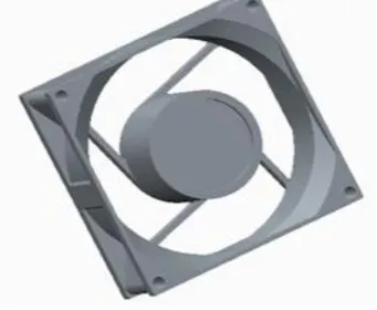
FIG 4.3 Model of the cooling fan casing created using Microscribe and Rhinoceros software
4.4 COMPARISON PHOTOCOPY OF MINIATURIZED AND PARENT COMPONENT MODEL
The experiment shows the difference between the both components and shows its objective. Here our objective is miniaturize the components and it plays an model role in daily life with a compact one.
FIG 4.4.1Prototype of miniaturized fan casing
FIG 4.4.2 Example for miniaturized product prototype
V. CONCLUSION
The paper outlines an idea to miniaturizing the component size using rapid prototyping and reverse engineering to meet the needs for recent manufacturing trends to manufacture a component in compact size.
Thus our objective of miniaturizing the component size is effectively done. In future we are trying to implement this concept without any loss in efficiency when compared to the parent component by finding a perfect angle for a fan blade.
Progress is not possible without its challenges, but it is achievable. Remanufacturing companies have also build up new reverse engineering know how to find methodological innovations and they need to develop new technologies. This paper creates an innovation idea for create a miniaturized component in future.
VI. FUTURESCOPE
In this Journal, we prepare the miniaturized size of the casing of the cooling fan. Our future scope is to find the perfect angle for the miniaturized cooling fan blade to fulfill the usage of cooling. The efficiency will be improved by changing the angle of fan will be designed in future.
ACKNOWLEDEGMENT
The Authors acknowledge AICTE for their financial support in funding to do this project under MODROBS.
Copyright to IJIRSET www.ijirset.com 1837 4. Dr. D. Chandra Mohan, Dr. K .Marimuthu, A rapid prototyping and rapid tooling-A Overview and its application in Orthopaedics, International journal of advanced technology.
5. DepikaJijothiya and PrabhuLalVerma, A Survey of Performance based rapid prototyping techniques, Scholars Journal of engineering and technology. Sch. J. Eng. Tech., 2013; 1(1):4-12
6. Chua, C.K. and Leong, K.F. “Rapid prototyping: Principles and applications in manufacturing”, John Wiley and Sons Inc.,1997
7. Prashant k. jain Advances in materials for powder based rapid prototyping. In Proceedingof International Conference on Recent Anvances in