The protoDUNE Single Phase Detector Control System
AntoineKehrli1,GiovannaLehmann Miotto1,XavierPons1,SylvainRavat1, andManuel J. Rodriguez1,2,∗
1CERN, Genève, Switzerland 2CIEMAT, Madrid, Spain
Abstract. This paper presents the Detector Control System (DCS) that has been designed and implemented for the NP04 experiment at CERN. NP04, also known as protoDUNE Single Phase (SP), aims at validating the engineering processes and detector performance of a large Liquid Argon (LAr) Time Pro-jection Chamber (TPC) in view of the DUNE experiment. Built at the CERN Neutrino Platform (NP) facilities, it started to operate in September 2018 af-ter two years of construction and commissioning, using a af-tertiary beam of the CERN SPS accelerator. After an overall description of the distributed control architecture that has been chosen for the control of this experiment, focus will be put on describing the software system design, based on the CERN control frameworks UNICOS and JCOP (built on top of WINCC OA). The knowledge acquired during the operation of the DCS is discussed and future work are pre-sented.
1 Introduction
NP04 is the single-phase Time Projection Chamber (TPC) prototype for the DUNE Far Detec-tor [1]. Built at the CERN Neutrino Platform (NP) facilities, it started to operate in Septem-ber 2018 after two years of construction and commissioning [2]. Installed on a new dedicated charged-particle test beamline, it provides the means to achieve a better understanding of the interaction processes occurring within an argon target. The detector elements, consisting of the TPC, which data is read using the cold electronics (CE) system, and the photon detection system (PDS), are housed in a cryostat filled with Liquid Argon (LAr) as target material. The cryostat, a free-standing steel-framed vessel with an insulating double membrane, is based on the technology used for liquefied natural gas (LNG) storage and transport. A cryogenic system maintains the LAr at a stable temperature of 87.7 K and at the required purity level through a closed-loop process that recovers the evaporated argon, recondenses and filters it, and returns it to the cryostat.
The TPC consists of two drift volumes, defined by a central cathode plane –called the Cathode Plane Assembly (CPA)– that is flanked by two anode planes and a field cage (FC) that surrounds the entire active volume. The CPA is held at –180 kV providing the 500 V/cm
drift field in the 3.6-m-deep drift regions. Uniformity of the electric field is guaranteed by the surrounding FC. Each anode plane is constructed of three adjacent Anode Plane Assemblies (APAs) that are each 6 m high by 2.3 m wide in the installed position. Each APA consists
of a frame that holds three parallel planes of sense and shielding wires; the wires of each plane are oriented at different angles with respect to those on the other planes to enable
3D reconstruction. The CE, mounted onto the APA frame, and therefore immersed in LAr, amplifies and continuously digitizes the induced signals on the sense wires at 2 MHz, and transmits these waveforms to the Data Acquisition (DAQ) system.
This paper describes the Detector Control System (DCS) used on NP04. The first part is focused on the hardware integration (Sections 2 and 3). The second part of the document (section 4) describes the supervisory software used. To conclude, the experience acquired during its development and commissioning is given.
2 DCS hardware components
A DCS involves all the elements (hardware and software) that allow the correct operation of the detector. It is in charge of monitoring and controlling the detector, observing its state and manipulating its subcomponents. Safe and coherent operations are the primary requirements for a DCS. The DCS provides a uniform interface to all the detector subsystems to achieve the coherent operations. The safe operation is achieved by monitoring all the incoming data from the detector. An alarm system reads these data to report any abnormal conditions to the operator. Depending on the severity of the alarms, the DCS can alert the experts through email or SMS and take assisted or automatic corrective actions. One of these corrective actions is the firing of hardwired interlocks to protect the detector and its subsystems from detrimental operations or situations.
Since protoDUNE is a prototype, it is thoroughly instrumented to validate the design from the perspective of basic detector performance. The data gathered from the sensors as well as the current, voltage and temperature variations of the power supplies are monitored ad a high granularity and archived for online and offline analysis at a much higher rate that normally
expected by a DCS system (known historically as slow control). A brief description of the different subsystems, and how the DCS manage them, is given in the following.
Detector power control: The detector power control (DPC) is composed of the power sup-plies that provide power to the different parts of the detector. Explained in detail in section 4,
the DCS is in charge of processing the requests from the operators, and send the commands to the power supplies. Additionally, the DCS monitors and archives the power supply param-eters, such as currents, voltages, temperatures allowing an analysis of the system behavior over time. A supervisory system is implemented, displaying an alarm in case any of the con-figured limits is exceeded. Depending on the severity of the alarms, corrective actions may be taken automatically to protect the detector.
Photon detectors: When a charged particle traverses the detector, the LAr scintillates, gen-erating photons with a wavelength of 128 nm. The LAr scintillation is detected using a light collection system together with light sensors and its readout electronics. Using these data, the Photon Detector System (PDS) provides additional event information. Furthermore, this information can be helpful in performing background rejection and triggering on non-beam events. The DCS provides an interface with the PDS for monitoring its working conditions and tuning its configuration for accurate operation. These configurations can be stored in a file and imported by the DCS.
TPC electronics: The TPC electronics, as part of the read-out system, are usually referred to as theCold Electronicsbecause they stay immersed in the LAr. To guarantee their correct operation, it is essential to monitor their operational parameters. The DCS must check these parameters and warn or activate an interlock in case of malfunction.
High voltage system: The high voltage system is responsible for providing the required electrical field inside the cryostat. The objective is to achieve an electrical field of 500 V/cm.
For this, a special high power supply is used, a Heinzinger power supply able to provide up to -200kV [3]. The control of this power supply is critical since a single failure may harm the whole detector. The low-level control of the power supply relies on a robust real-time system from National Instruments [4]. However, the DCS is in charge of sending commands to this system and monitoring its output to unify all the systems under the same interface.
Ground planes monitor: Several ground planes are placed above and below the field cage to contain the electrical field generated by the high voltage system. By monitoring current spikes on the ground planes is possible to detect if there is a spark on the field cage and diagnose approximately where the failure is. This information is used by the real-time system controlling the high voltage power supply to adjust the voltage or even trip the power supply if it reaches a predefined threshold. The DCS receives this information, displays and archives it for further analysis.
Gradient temperature monitor: A set of 92 high precision temperature sensor has been placed inside the cryostat. Organized into two vertical profilers and two horizontal 2-dimensional profilers, they provide a detailed temperature map of the liquid argon (LAr) inside the cryostat. This map is necessary to validate the computational fluid dynamics (CFD) model and simulations. The DCS must read these sensors with a precision of 3 mK. An elec-tronic circuit was designed at CERN to provide a compact readout of those sensors with the required precision.
Purity monitors: The three purity monitors used in NP04 are designed to measure the electron drift lifetime in the LAr over the range from 100µs up to several milliseconds [2]. The devices were originally developed for the ICARUS experiment [5]. By exciting a photo-cathode with the light from a xenon-flash lamp, it is possible to measure the electron drift lifetime as a function of the charge emitted by the photo-cathode and the charge collected in a fixed internal anode.
Operating the purity monitors while the detector is taking data may affect the photon detectors
decreasing the data quality. An interlock system has been deployed on the DCS to avoid the purity monitors operating during standard data taking.
Ground impedance monitor: The use of a single-phase TPC implies that there is no charge amplification in the liquid. Therefore, the electronics must be extremely sensitive, and grounding and shielding are critical. The detector ground is isolated from the building ground, and the DCS monitors the ground decoupling through a Ground Impedance Monitor. If a grounding problem is detected, the ground impedance monitor sounds an alarm. The DCS alerts operators and records incoming data.
Cryostat monitoring and control: Numerous sensors have been placed in the cryostat to monitor its physical conditions. Temperature and pressure sensors monitor the insulation space together with several valves to control the pressure in the insulation membrane. A set of displacement and strain gauges have been placed to monitor the mechanical behaviour of the cryostat. Furthermore, the DCS monitors the Beam Plug state –a particular device to minimize the loss of energy from the particle beam before it enters the active volume of the TPC– checking the current passing through it, its internal pressure and temperature.
temperatures. Electro-valves regulate the water flow and the fans built into the racks adapt the speed according to the local heat load. The DCS system monitors all working parameters of the water circuit and of the racks and is able to cut power if the ambient temperature raises beyond a settable threshold. It also controls the staged re-powering of racks during a cold start procedure, in order to limit the instantaneous load in the electric distribution system.
External systems: The cryogenics control system does not belong to the DCS. However, the DCS and the cryogenics control system continuously exchange information. It is responsible for purging, cooling down and filling the cryostat, acquiring and maintaining the temperature of the Liquid Argon (LAr) on its nominal temperature within a range of±0.1K, purifying the LAr outside the cryostat and re-condensing and purifying the boil-offGaseous Argon (GAr)
Similarly to the cryogenics control system, the Beam Line control and instrumentation is a standalone system. Nevertheless, the communication between the DCS and Beam Line is crucial for the DAQ system and the appropriate detector operation.
3 Unifying an heterogeneous system
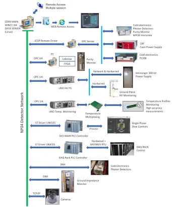
Ideally the DCS provides a homogeneous environment into which all its parts can be inte-grated. This environment for the NP04 experiment is depicted in Figure 1. The communica-tion protocols used to interact with different hardware components are, in most cases, fixed
by the manufacturers. Therefore, the DCS has to be able to support a variety of communica-tion mechanisms and to abstract those, such that their difference is not visible to the higher
levels of the supervisory system, as well as to the operators. The communication layers used within NP04 and their main characteristics are listed here:
• OPC classic (OLE1for Process Control Data Access): The OPC Classic specifications are widely used in the Industry as the standard interface for hardware communication [6].The OPC Classic specifications provide a middleware to decouple the hardware specific ele-ments from the software in charge of its control. Wiener power supplies [7] used in the detector for powering the CE (low voltage and high voltage) and PDS, provide the OPC Data Access (OPC DA) interface.
• OPC unified architecture: The OPC Unified Architecture (OPC UA) was designed to en-hance and surpass the capabilities of the OPC Classic specifications [8]. Its functionality remains the same but with several improvements that ease its operation. The DCS uses the OPC UA interface to communicate with the CompactRIO (cRIO) [4] employed for the high voltage system and ground planes monitoring. A second cRIO is additionally in use for the temperature gradient monitor. To communicate with the purity monitors, OPC UA is also chosen.
• SIEMENS S7 driver: The NP04 DCS uses several PLCs from SIEMENS [9] to monitor and control of wired signals. SIEMENS provides a standard interface to communicate with the PLCs. Using a specific driver, the DCS is capable of sending commands to the PLC and read its variables.
• Distributed information management (DIM): The DIM system [10] was designed at CERN as a multipurpose communication layer with the aim of unifying the requirements and constraints for the different detector operations. The DIM system is in use for monitor and
control the PDS, front-end electronics and ground impedance monitor.
temperatures. Electro-valves regulate the water flow and the fans built into the racks adapt the speed according to the local heat load. The DCS system monitors all working parameters of the water circuit and of the racks and is able to cut power if the ambient temperature raises beyond a settable threshold. It also controls the staged re-powering of racks during a cold start procedure, in order to limit the instantaneous load in the electric distribution system.
External systems: The cryogenics control system does not belong to the DCS. However, the
DCS and the cryogenics control system continuously exchange information. It is responsible for purging, cooling down and filling the cryostat, acquiring and maintaining the temperature of the Liquid Argon (LAr) on its nominal temperature within a range of±0.1K, purifying the LAr outside the cryostat and re-condensing and purifying the boil-offGaseous Argon (GAr)
Similarly to the cryogenics control system, the Beam Line control and instrumentation is a standalone system. Nevertheless, the communication between the DCS and Beam Line is crucial for the DAQ system and the appropriate detector operation.
3 Unifying an heterogeneous system
Ideally the DCS provides a homogeneous environment into which all its parts can be inte-grated. This environment for the NP04 experiment is depicted in Figure 1. The communica-tion protocols used to interact with different hardware components are, in most cases, fixed
by the manufacturers. Therefore, the DCS has to be able to support a variety of communica-tion mechanisms and to abstract those, such that their difference is not visible to the higher
levels of the supervisory system, as well as to the operators. The communication layers used within NP04 and their main characteristics are listed here:
• OPC classic (OLE1for Process Control Data Access): The OPC Classic specifications are
widely used in the Industry as the standard interface for hardware communication [6].The OPC Classic specifications provide a middleware to decouple the hardware specific ele-ments from the software in charge of its control. Wiener power supplies [7] used in the detector for powering the CE (low voltage and high voltage) and PDS, provide the OPC Data Access (OPC DA) interface.
• OPC unified architecture: The OPC Unified Architecture (OPC UA) was designed to en-hance and surpass the capabilities of the OPC Classic specifications [8]. Its functionality remains the same but with several improvements that ease its operation. The DCS uses the OPC UA interface to communicate with the CompactRIO (cRIO) [4] employed for the high voltage system and ground planes monitoring. A second cRIO is additionally in use for the temperature gradient monitor. To communicate with the purity monitors, OPC UA is also chosen.
• SIEMENS S7 driver: The NP04 DCS uses several PLCs from SIEMENS [9] to monitor and control of wired signals. SIEMENS provides a standard interface to communicate with the PLCs. Using a specific driver, the DCS is capable of sending commands to the PLC and read its variables.
• Distributed information management (DIM): The DIM system [10] was designed at CERN as a multipurpose communication layer with the aim of unifying the requirements and constraints for the different detector operations. The DIM system is in use for monitor and
control the PDS, front-end electronics and ground impedance monitor.
1OLE stands for Object Linking and Embedding
EWϬ ϰĞ ƚĞĐƚ Žƌ EĞ ƚǁ Žƌ Ŭ ŽůĚĞůĞĐƚƌŽŶŝĐƐ WŚŽƚŽŶĞƚĞĐƚŽƌƐ WƵƌŝƚLJDŽŶŝƚŽƌ DWKŵŝŶŝĐƌĂƚĞ ZED/E t/EK d^ZsZ ;>ŝŶƵdžͿ tZĞŵŽƚĞĐĐĞƐƐ Remote Access Multiple session ,ĞŝŶnjŝŶŐĞƌϯϬϬŬs WŽǁĞƌ^ƵƉƉůLJ ĐZ/K ,sW^ ,ĂƌĚǁŝƌĞĚ 'ƌŽƵŶĚWůĂŶĞ ,sDŽŶŝƚŽƌŝŶŐ dĞŵƉĞƌĂƚƵƌĞWƌŽĨŝůĞƐ DŽŶŝƚŽƌŝŶŐ ,ŝŐŚĂĐĐƵƌĂĐLJ ŵĞĂƐƵƌĞŵĞŶƚƐ EĞƚǁŽƌŬΘ,ĂƌĚǁŝƌĞĚ >ĂďǀŝĞǁ &W' WƵƌŝƚLJ DŽŶŝƚŽƌ W dĞŵƉĞƌĂƚƵƌĞ DƵůƚŝƉůĞdžŝŶŐ ^ŝŶŐůĞWŚĂƐĞ ^ůŽǁŽŶƚƌŽůƐ ^ϳƌŝǀĞƌhE/K^ WƌŽĐĞƐƐ ^D/EW>ŽŶƚƌŽůůĞƌ ,ĂƌĚǁŝƌĞĚн DKh^Zdh /D ŽůĚůĞĐƚƌŽŶŝĐƐ WŚŽƚŽŶĞƚĞĐƚŽƌƐ 'ƌŽƵŶĚ/ŵƉĞĚĂŶĐĞ DŽŶŝƚŽƌ YZ< ŽŶƚƌŽů dWͬ/W KW^ĞƌǀĞƌ ŽůĚĞůĞĐƚƌŽŶŝĐƐ W>ϱϬϲ :KWZĞŵŽƚĞƌŝǀĞƌ Zd ĂĞŶWŽǁĞƌ^ƵƉƉůLJ KWh KWh ĐZ/K dĞŵƉ͘DŽŶŝƚŽƌŝŶŐ KWh ^ϳƌŝǀĞƌhE/K^ YZĂĐŬW>ŽŶƚƌŽůůĞƌ /D ĂŵĞƌĂƐ
Figure 1.Diagram of the NP04 DCS topology. All the subsystems in the DCS are connected to a ded-icated network, the NP04 detector network. The DCS can communicate with each different subsystem using several communication protocols (drawn in blue arrows). Furthermore, the DCS is accessible over the internet using a remote connection protocol, and the most relevant data is published in a web server for real-time off-site monitoring.
4 Detector operation
The primary challenge for the NP04 DCS was its extremely tight development and installation schedule. The detector was built and commissioned in two years. For that reason, the DCS needed to rely on existing solutions. The software chosen to operate the DCS is a commercial supervisory control and data acquisition (SCADA) toolkit –extensively used at CERN– from SIEMENS called SIEMENS Simatic WinCC Open Architecture (WinCC OA) [12]. WinCC OA is based on a distributed product, where quasi-independent processes, called managers, execute different tasks. Those managers do not need to run on the same machine and may
be distributed, together with the WinCC OA internal database, to several computers running on Windows or Linux. This feature is handy since it does not restrict the DCS to a specific environment, making it more flexible and easier to implement.
Built on top of WinCC OA, two CERN frameworks are in use in the NP04 DCS. The Joint COntrol Project (JCOP) [13] and the UNified Industrial COntrol System (UNICOS) [14] frameworks provide a full set of components allowing fast development of any detec-tor control system. Tools such as automatic PLC project generation, predefined widgets and faceplates, external database communication for archiving, specialized trend tools or config-urable alarm settings are just a few examples of those features. A critical component in the NP04 DCS is the Access Control component. With the access control enabled, every user logs in with his personal account to perform any DCS action. Three authorization levels are in use: Monitor, Operator, and Expert. Depending on the user’s rights, different actions can
be blocked or hidden to protect the detector integrity and to better guide the user. The Finite State Machine (FSM) component is another important component in use in NP04: it abstracts the system complexity exposing only simple actions (e.g. ON/OFF) to the operator.
4.1 Basic operation
The basic operation of the detector uses a simplified interface that allows to the operators a smooth execution of their tasks, minimizing unintended actions and therefore increasing the stability of the system. For monitoring purposes, the interface uses simple color coding in order to be as straightforward as possible. It is based on two main concepts:
• Dynamic objects, where all the graphical items are dynamic and thus can be used to navi-gate through the different parts of the detector to see its dedicated panels.
• Data widget, where the datum displayed on the DCS interface is more than a pure value and the operators may perform some extra actions such as plotting its historical values or check its status.
Zz K&&
ZZKZ EKdͺZz
^ǁŝƚĐŚͺKE ^ǁŝƚĐŚͺK&& ZĞĐŽǀĞƌ ^ǁŝƚĐŚͺK&&
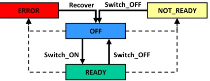
Figure 2.Finite State Machine diagram.
4 Detector operation
The primary challenge for the NP04 DCS was its extremely tight development and installation schedule. The detector was built and commissioned in two years. For that reason, the DCS needed to rely on existing solutions. The software chosen to operate the DCS is a commercial supervisory control and data acquisition (SCADA) toolkit –extensively used at CERN– from SIEMENS called SIEMENS Simatic WinCC Open Architecture (WinCC OA) [12]. WinCC OA is based on a distributed product, where quasi-independent processes, called managers, execute different tasks. Those managers do not need to run on the same machine and may
be distributed, together with the WinCC OA internal database, to several computers running on Windows or Linux. This feature is handy since it does not restrict the DCS to a specific environment, making it more flexible and easier to implement.
Built on top of WinCC OA, two CERN frameworks are in use in the NP04 DCS. The Joint COntrol Project (JCOP) [13] and the UNified Industrial COntrol System (UNICOS) [14] frameworks provide a full set of components allowing fast development of any detec-tor control system. Tools such as automatic PLC project generation, predefined widgets and faceplates, external database communication for archiving, specialized trend tools or config-urable alarm settings are just a few examples of those features. A critical component in the NP04 DCS is the Access Control component. With the access control enabled, every user logs in with his personal account to perform any DCS action. Three authorization levels are in use: Monitor, Operator, and Expert. Depending on the user’s rights, different actions can
be blocked or hidden to protect the detector integrity and to better guide the user. The Finite State Machine (FSM) component is another important component in use in NP04: it abstracts the system complexity exposing only simple actions (e.g. ON/OFF) to the operator.
4.1 Basic operation
The basic operation of the detector uses a simplified interface that allows to the operators a smooth execution of their tasks, minimizing unintended actions and therefore increasing the stability of the system. For monitoring purposes, the interface uses simple color coding in order to be as straightforward as possible. It is based on two main concepts:
• Dynamic objects, where all the graphical items are dynamic and thus can be used to navi-gate through the different parts of the detector to see its dedicated panels.
• Data widget, where the datum displayed on the DCS interface is more than a pure value and the operators may perform some extra actions such as plotting its historical values or check its status.
Zz K&&
ZZKZ EKdͺZz
^ǁŝƚĐŚͺKE ^ǁŝƚĐŚͺK&& ZĞĐŽǀĞƌ ^ǁŝƚĐŚͺK&&
Figure 2.Finite State Machine diagram.
For basic control operations, the DCS uses the FSM component from JCOP [15]. The FSM component provides the tools necessary to implement an FSM on a detector control
system. The FSM act as an abstraction layer simplifying the control of the detector. Based on a well-defined set of states and transitions between states, each part of the detector can be controlled hierarchically. Once the topology of the detector is defined, the FSM component is responsible for propagating the actions sent to the different parts of the detector and obtaining,
as a result of these actions or asynchronous incidents, their corresponding states. An example of the FSM used for the detector power control is shown in the Figure 2. Access Control, implemented in the FSM, grants the safe operation of the detector.
4.2 Advanced operation
For advanced detector operations, specific and more details panels have been designed. Rather than using an FSM for moving the detector –or its subcomponents– to a preset state, the advanced panels allow the experts, credited by the access control, the full control of the different parts of the detector. The advanced panels connect with the lowest level architecture
of the detector, allowing the experts to modify operational parameters, set limits for alerts or directly control critical devices out of the scope of the FSM.
5 Conclusions and future plans
Many collaborators and institutes have contributed to the design, implementation and in-stallation of the NP04 experiment: the systems composing it are very varied, ranging from large detector modules with custom electronics, to specialized cryogenics instrumentation, to industrial equipment. A large effort was made to unify, as much as possible, the choice
of components, such as, e.g., the power supplies and PLCs. This effort, combined with the
choice of using the JCOP and UNICOS frameworks, which are built on top of WinCC OA and have been developed over two decades by many CERN engineers, has allowed a very small team of four people dedicating only part of their time to this project, to develop the complete DCS software for NP04. One of the most challenging aspects of NP04 is the con-trol and steady operation of the high voltage circuit at 180 kV. The concon-trol and monitoring system for this component uses a high performance FPGA based system, sampling the analog outputs of the power supply at very high rate. This system has been proven to be a great tool to understand the behaviour of the power supply and the overall response of the detector to the high electric field and its variations. It is being continuously improved to fine-tune control actions and identify the best operating point of the power supply.
The future of the DCS aims to increase the autonomy of the system. Automated recovery actions can be designed to move the entire detector –with the subsystems involved– to a recovery state to enable the apparatus to recover from several well-known errors without intervention from the operators. This can only be achieved thanks to the coherence of the implemented system, in the way that several subsystems can be interconnected to deploy global autonomous tasks. Several of these actions are currently under development and will be implemented in the next DCS upgrade.
References
[1] R. Acciarri, M.A. Acero, M. Adamowski, C. Adams, P. Adamson, S. Adhikari, Z. Ah-mad, C.H. Albright, T. Alion, E. Amador et al., Tech. rep. (2016), http://arxiv. org/abs/1601.02984
[3] Heinzinger electronic GmbH,Heinzinger,https://www.heinzinger.com/
[4] National Instruments, CompactRIO Systems, http://www.ni.com/en-us/shop/ compactrio.html
[5] S. Amerio, S. Amoruso, M. Antonello, P. Aprili, M. Armenante, F. Arneodo, A. Badertscher, B. Baiboussinov, M. Baldo Ceolin, G. Battistoni et al., Nuclear In-struments and Methods in Physics Research527, 329 (2004)
[6] OPC Foundation, OPC Classic specifications, https://opcfoundation.org/ about/opc-technologies/opc-classic/
[7] WIENER,WIENER Power Electronics,http://www.wiener-d.com/
[8] OPC Foundation,OPC Unified Architecture,https://opcfoundation.org/about/ opc-technologies/opc-ua/
[9] Siemens AG, SIMATIC Controllers - Industrial Automation Systems, https: //www.siemens.com/global/en/home/products/automation/systems/ industrial/plc.html
[10] C. Gaspar, M. Dönszelmann, P. Charpentier, Computer Physics Communications140, 102 (2001)
[11] B. Copy, I. Prieto Barreiro, F. Varela, E. Mandilara,Monitoring of CERN’s Data In-terchange Protocol (DIP) system, inICALEPCS(2018),http://inspirehep.net/ record/1656451/
[12] Siemens AG, SCADA System SIMATIC WinCC Open Architecture, http:///www. siemens.com/wincc-open-architecture
[13] O. Holme, S. Schmeling, M. González-Berges, P. Golonka,The JCOP Framework, in 10th International Conference on Accelerator and Large Experimental Physics Control Systems(Geneva, 2005), p. 6
[14] H. Milcent, E. Blanco, F. Bernard, P. Gayet, UNICOS: AN OPEN FRAMEWORK, in ICALEPCS(2009)