Determination of Conversion Factor for
Different Types of Beams Using FEM
Kedar Patil
1, Shamuvel Pandit
2, Avadhut Jadhav
3, Ranjeet Mithari
4, M S Shinge
5Assistant Professor, Department of Mechanical Engineering,Bharati Vidyapeeth College of Engineering, Kolhapur,
Maharashtra, India1,2,3,4,5
ABSTRACT:In this study, a conversion factor between BEAM188 and SOLID186 elements is obtained in ANSYS. ANSYS is been used as a FEA tool. Conversion factor helps in predicting natural frequencies that would be obtained if SOLID186 element would have been used thereby reducing solution time. Frequency obtained by using BEAM188 element; when multiplied by conversion factor; gives the frequency that will be obtained by using SOLID186 element. In order to verify this, beams with three boundary conditions i.e. Fixed-Fixed, Fixed-Free and Simply Supported were used with varying slenderness ratio from 20 and 6. Finding out the variation in hand calculations and those using ANSYS as a tool was another aim. This variation is caused owing to the fact that hand calculations follow Euler-Bernoulli beam theory whereas elements used in ANSYS software followed Timoshenko beam theory. Timoshenko beam theory considers shear deformation whereas Euler-Bernoulli neglects it. Both theories have their own assumptions leading to the variation in solutions obtained by both of them.
KEYWORDS:Conversion factor, Natural frequency, Mode shapes, BEAM188 element, Solid186 element, ANSYS, MS-Excel, Slenderness ratio, Timoshenko beam theory, Euler-Bernoulli beam theory.
.
I. INTRODUCTION
Natural frequency is an important parameter to be considered while designing any structure. When frequency of external force applied becomes equal to natural frequency, resonance occurs. Resonance is a very hazardous phenomenon and should be avoided. Hence in order to obtain a robust design, one must know the natural frequency of that structure. Beams are an important part of any structure In reality most structures, such as beams, are continuous systems that have more complex equations of motion and have multiple natural frequencies. Beams are a fundamental engineering structures used in multiple disciplines of engineering. The primary use of beam is to withstand loading that induces bending or buckling.
To solve these more complex problems finite element analysis software is used. Finite element analysis software packages, such as ANSYS, have beam element classes. These classes of elements are governed by Euler-Bernoulli beam theory and Timoshenko beam theory. Beam elements take less time for solving any problem but their application is limited to thin beams. For thicker beams, solid elements are recommended. However, they take a lot of time for solving and are computationally expensive. Due to more number of nodes, expert handling is required too. Conversion factor aims at eliminating this difficulty. Conversion factor is obtained by dividing the natural frequency obtained by using solid element by that using beam element. Thus, for a given mode, multiplying the natural frequency of beam obtained by using beam element by conversion factor will give the natural frequency that could have been obtained if solid element was used.
SOLID186; follow Timoshenko beam theory. This will also help in finding the variation in solutions obtained by software to that of hand calculation which follows Euler-Bernoulli beam theory. This variation is caused because of difference in basic assumptions of both theories. Timoshenko beam theory considers shear deformation whereas Euler-Bernoulli beam theory neglects it. Another difference between these two is that in Euler-Euler-Bernoulli beam theory, stress in direction of thickness is considered to be zero whereas in Timoshenko beam theory, it is non-zero.
II. METHODOLOGY
In this study, three cases i.e. Fixed-Fixed, fixed- free and simply supported beams were utilized with point loads. For all three cases the geometry was varied in order to vary the slenderness ratio. Slenderness ratio was varied between 6 and 20. Table shows the geometries for all beams with varying slenderness ratio. For all cases, initially beam was 300mm long and had a cross section of 0.5mm*0.5mm. Mild steel is the reference material considered for beam and it
has the density of 8050 kg/m3, elastic modulus is 210 GPa, Poisson's ratio is 0.3and carrying a mass of 100 kg. Hand
calculations were followed by analysis usingANSYS wheresameproblems with varying slenderness ratios were modelled using BEAM188 and SOLID186 elements.
2.1. Solution using hand calculations 2.1.1. Problem on Fixed-free beam
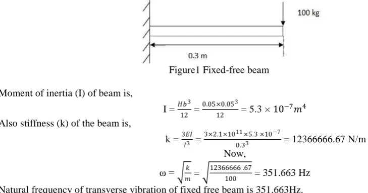
A Fixed-free beamcarrying a mass of 100 kgat the free end and having all above properties is considered and natural frequency of transverse vibration of beam is found out using analytical way. After applying all these 4 steps, we get a filtered image that contains only text regions.
Figure1 Fixed-free beam
Moment of inertia (I) of beam is,
I = 𝐻𝑏
3
12 =
0.05×0.053
12 = 5.3 × 10
−7𝑚4
Also stiffness (k) of the beam is,
k = 3𝐸𝐼 𝑙3 =
3×2.1×1011×5.3 ×10−7
0.33 = 12366666.67 N/m
Now,
ω = 𝑚𝑘 = 12366666 .67
100 = 351.663 Hz
Natural frequency of transverse vibration of fixed free beam is 351.663Hz.
2.1.2. Problem on Fixed-fixed beam
A Fixed-fixed beam carrying a mass of 100 kg at its center and having all above properties is considered and natural frequency of transverse vibration of beam is found out using analytical way.
Figure 2 Fixed-Fixed beam We know moment of inertia of beam,
I = 𝐻𝑏
3
12 =
0.05×0.053
12 = 5.3 × 10
−7𝑚4
Also, Stiffness (k) of the beam is,
k = 192𝐸𝐼 𝑙3 =
192×2.1×1011×5.3 ×10−7
0.33 = 791466666 N/m
Now,
ω = 𝑚𝑘 = 791466666
100 = 2813.302 Hz
Natural frequency of transverse vibration of fixed-fixed beam is 2813.302 Hz.
2.1.3. Problem on Simply supported beam
Figure 3 simply supported beam We know moment of inertia of beam,
I = 𝐻𝑏
3
12 =
0.05×0.053
12 = 5.3 × 10
−7𝑚4
Also stiffness (k) of the beam is,
k = 48𝐸𝐼
𝑙3 =
48×2.1×1011×5.3 ×10−7
0.33 = 197866666 N/m
Now,
ω = 𝑘
𝑚 =
197866666
100 = 1406.65 Hz
Natural frequency of transverse vibration of simply supported beam is 1406.65 Hz.
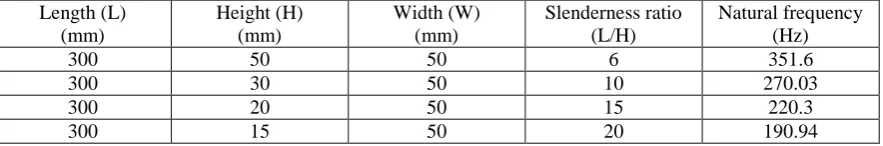
In same manner, Fixed-free beam case, Fixed-fixed beam case and simply supported beam case is solved for different slenderness ratio and results obtained for each case of beam is tabulated below:-
Table 1 Fixed-Free beam Length (L) (mm) Height (H) (mm) Width (W) (mm) Slenderness ratio (L/H) Natural frequency (Hz)
300 50 50 6 351.6
300 30 50 10 270.03
300 20 50 15 220.3
300 15 50 20 190.94
Table 2 Fixed-Fixed beam
Length (L) (mm) Height (H) (mm) Width (W) (mm) Slenderness ratio (L/H) Natural frequency (Hz)
300 50 50 6 2813.3
300 30 50 10 2160.25
300 20 50 15 1762.4
300 15 50 20 1527.53
Table 3 simply supported beam
Length (L) (mm) Height (H) (mm) Width (W) (mm) Slenderness ratio (L/H) Natural frequency (Hz)
300 50 50 6 1406.6
300 30 50 10 1080.12
300 20 50 15 881.92
300 15 50 20 763.76
2.2. ANSYS modeling and computation:
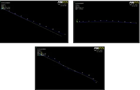
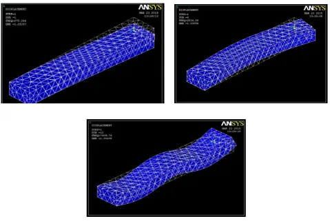
Fig.4 Example of BEAM188 element model Fig.5 Example of SOLID186 element model
Each problem case was solved for all cross sections considered. Modal analysis method was used since we were dealing with natural frequency and mode shapes of vibration.
Figure 7 Illustrations of mode shape no. 1, 5, and 10 for Fixed-Free beam case with solid element SOLID186.
III.RESULTSANDDISCUSSION 3.1. Comparison of hand calculation and ANSYS results
All the three problems considered were solved by hand calculation and using ANSYS as tool for FEM. Further, in ANSYS, same problem was solved twice; firstly by using BEAM188 element and then by using SOLID186 element. Frequency comparison for each type of boundary conditions is show in following tables.
Table 3.1 Frequency comparison of hand calculation vs. ANSYS for Fixed-Fixed beam case.
Slenderness ratio (L/H) 6 10 15 20
Solid element frequency (Hz) 2526.2 1669.5 1157.6 880.56
Beam element frequency (Hz) 2538 1681.8 1162.3 594.66
Hand calculationfrequency (Hz) 2813.3 2160.25 1762.4 1527.53
Slenderness ratio (L/H) 6 10 15 20
Solid element frequency (Hz) 452.53 275.24 184.5 138.76
Beam element frequency (Hz) 449.04 273.1 182.86 91.67
Hand calculationfrequency (Hz) 351.6 270.03 220.3 190.94
Table 3.3 Frequency comparison of hand calculation vs. ANSYS for Simply Supported beam
Slenderness ratio (L/H) 6 10 15 20
Solid element frequency (Hz) 1193.2 755.78 511.02 384.84
Beam element frequency (Hz) 1471.2 1112.7 1033.8 538.34
Hand calculationfrequency (Hz) 1406.6 1080.12 881.92 763.76
The deviation in between hand calculations and ANSYS solution is less at lower slenderness ratios and increases with increasing slenderness ratio. For lower slenderness ratios, the hand calculation results are closer to that using beam and solid elements. However, this varies for higher slenderness ratios. The beam and solid element results diverge from hand calculated results to a greater extent at higher slenderness ratios. For example, for Fixed-Free beam with slenderness ratio 6, the deviation of solid element solution from hand calculations was 22.3% which increased to 33.94% for slenderness ratio 30. Same was observed for Fixed-Fixed and Simply Supported beams.
3.2. Overview of results
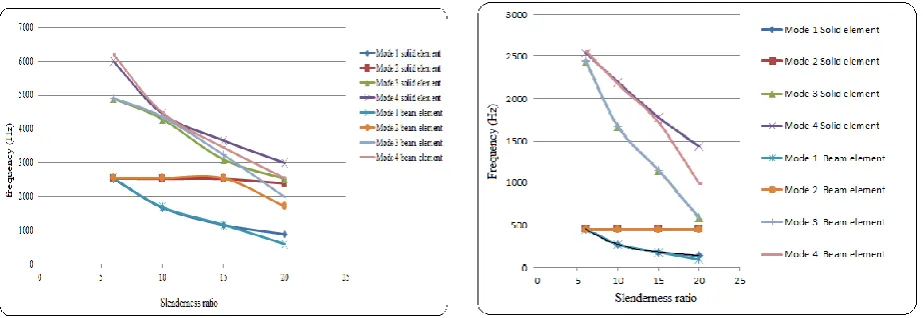
Solutions for all cases were obtained using hand calculations and ANSYS. Four modes were considered and a plot of frequency vs. slenderness ratio was made in MS-Excel for all three beam cases which can be seen in following figures.
Fig.10. Frequency comparison for Simply Supported beam
It is observed that as the slenderness ratio increases, the solution for considered elements diverge. The solutions obtained by using solid element were higher than those with beam element. This is due to higher nimber of nodes and greater complexity of solid element than that of beam. Single BEAM188 element has 2 nodes whereas for SOLID186, there are 20 nodes. It is also observed that for lower modes, frequency is less than that for higher nodes for all slenderness ratios considered. This is because the higher order mode shapes are complicated. As mode shape complicates, the assumption that plane sections remain plane after bending does not holds that good.
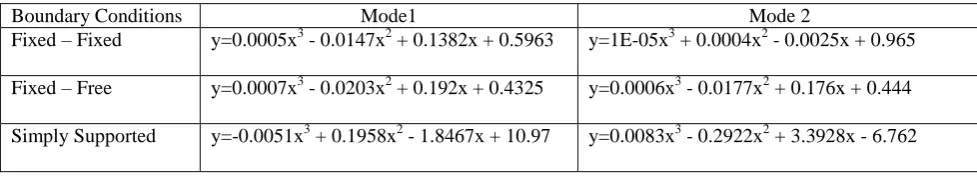
To obtain conversion factor, the frequencies obtained by solid element were divided by frequency obtained by beam element for same mode. A graph of these values was plotted against slenderness ratios. Then, using MS-Excel, a curve fit was obtained and a conversion factor equation based on slenderness ratio was generated. The conversion factor equations can be seen in table and table where y is the conversion factor and x is the slenderness ratio.
Conversion factor = frequency obtained using solid element frequency obtained using beam element
Table 3.4 Conversion factor equations for modes 1 & 2.
Boundary Conditions Mode1 Mode 2
Fixed – Fixed y= 0.0007x3 - 0.0208x2 + 0.2001x + 0.3987 y=0.0006x3 - 0.018x2 + 0.1733x + 0.4788
Fixed – Free y= 0.0007x3 - 0.0222x2 + 0.215x + 0.3628 y=-2E-06x3 + 9E-05x2 - 0.0017x + 1.015
Simply Supported y=0.0001x3 + 0.0864x2 - 1.651x + 15.133 y=0.0198x3 - 0.7946x2 + 9.8294x - 26.23
Table 3.4.2 Conversion factor equations for modes 3 & 4
Boundary Conditions Mode1 Mode 2
Fixed – Fixed y=0.0005x3 - 0.0147x2 + 0.1382x + 0.5963 y=1E-05x3 + 0.0004x2 - 0.0025x + 0.965
Fixed – Free y=0.0007x3 - 0.0203x2 + 0.192x + 0.4325 y=0.0006x3 - 0.0177x2 + 0.176x + 0.444
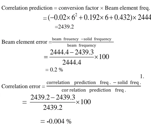
3.3. Validation of conversion factor
In order to validate the results obtained for beam cases, correlation error is calculated for any of the beam case.
Following table depicts frequency comparison for mode 3 of fixed free beam case.
Table 3.4.3. Frequency comparison for solid, beam and conversion factor
L/H 6 10 15 20 Solid element frequency 2439.30 1651.1 1136 860
Beam element frequency Hz.) 2444.4 1669.8 1146 583.57
Correlation prediction (Hz.) 2439.2 1651 1135.9 859.9
Beam element error (%) 0.2 1.1 0.87 -47.36
Correlation error (%) -0.004 -0.006 -0.008 -0.011 Correlation prediction = conversion factor × Beam element freq.
=
( 0.02 6
20.192 6 0.432) 2444.4
=2439.2Beam element error =beam freuency −solid frequency
beam frequency
2444.4 2439.3
100
2444.4
= 0.2 %
1.
Correlation error = correlation prediction freq . − solid freq .
cor relation prediction freq .
=
2439.2 2439.3
100
2439.2
=
-
0.004 %
We can see that, correlation error is very low proving the validity of conversion factor.
IV.CONCLUSION
For analysis of these beams, Euler-Bernoulli beam theory was stated. But due to it’s basic assumptions, it has certain limitations in its application. To overcome these limitations, Timoshenko beam theory was developed. Various software packages like ANSYS are available now-a-days which are based on Finite Element Method which give very quick solutions to these problems. In ANSYS, various elements like beam, solid, link, pipe, shell are available which the user can use for required application as suitable. Analysis using some elements like beam elements is comparatively easy and cheap. But its applications are limited to thin beams. For thicker beams, solid elements are recommended for obtaining desired accuracy in results. However, solid elements take a lot of time for solving and are computationally expensive and require expert handling.
theory. The use of conversion factor improved the solution accuracy like 3.25% to -0.31% for mode 4 of Fixed-Fixed beam.
REFERENCES
[1] S.S. Rao, “Mechanical vibrations”, 5th edition, 2011 [2] R.K. Bansal, “Strength of materials”,
[3] Palm, W. [2007], Mechanical Vibrations, Hoboken: Wiley & Sons [4] http://www.ewp.rpi.edu/hartford/~ernesto/SPR/Cosby-FinalReport