International Journal of Research (IJR)
e-ISSN: 2348-6848, p- ISSN: 2348-795X Volume 2, Issue 09, September 2015Available at http://internationaljournalofresearch.org
A Novel Approach to Implement Efficient SINR and Side-Lobe
Reduction by Using MIMO Radar Covariance Matrix
Bandi.Sravanthi
1,
Y.Nirmala
2& M. Pavani
31PG Scholar,Dept of ECE, KLR College Of Engineering And Technology, Paloncha, Khammam
District, Telangana
2 Assistant Professor, ,Dept of ECE, KLR College Of Engineering And Technology, Paloncha,
Khammam District, Telangana
3 Associate Professor ,HOD of Dept ECE, KLR College Of Engineering And Technology, Paloncha,
Khammam District, Telangana
ABSTRACT:
Multiple-input multiple-output (MIMO) radar has better parametric identifiability but compared to phased-array radar, it shows loss in signal-to-noise ratio due to non-coherent processing. To exploit the benefits of both MIMO radar and phased array, a waveform covariance matrix is proposed. To generate the proposed covariance matrix, the values of the cosine function between 0 and π with a step size of π/2 are used to form a positive semi-definite Toeplitz matrix, where is the number of transmit antennas. The proposed covariance matrix yields gain in the signal-to-interference-plus-noise ratio (SINR) compared to MIMO radar and have lower sidelobe levels (SLLs) compared to phased-array, MIMO-radar, and the recently proposed phased-MIMO scheme. Moreover, in contrast to the phased-MIMO scheme, where each antenna transmits a different power, our proposed scheme allows same power transmission from each antenna. Simulation results validate our analytical results.
Index Terms—Colocated antennas; MIMO-radar; phased- MIMO; Toeplitz matrix
INTRODUCTION
In the modern era of communications, the ability to send large volumes of data is crucial. With the increasing use of wireless LAN technology and third generation mobile telephony systems, the demand for data services has never been greater. The bandwidth of wireless communication systems is often limited by the cost of the radio spectrum required. Any increase in bit rate, which can be realised without increasing the bandwidth, makes the system more spectrally efficient and less costly. Traditional wireless communication systems have been made more spectrally efficient through the use of clever
coding techniques and algorithms. However, the fundamental bandwidth limitation does not change. Multiple Input Multiple Output (MIMO)
communication systems have been an
increasingly hot topic of research over the past eight years, due to their ability to greatly increase spectral efficiencies. In modern usage, “MIMO” specifically refers to a practical technique for sending and receiving more than one data signal on the same radio channel at the same time via multipath propagation.
MIMO:
MIMO exploits multipath, traditionally a pitfall in wireless communications, to enhance rather than degrade the signal. MIMO systems consist of multiple transmitters and multiple receivers. For MIMO systems to be most effective, a rich multipath scattering environment is needed to create independent propagation channels. It is the rich scattering in the propagation channel, which offers multiple parallel sub channels at the same frequency, therefore giving higher capacities over the same bandwidth.
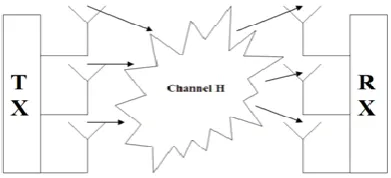
Fig : Three Element MIMO system
International Journal of Research (IJR)
e-ISSN: 2348-6848, p- ISSN: 2348-795X Volume 2, Issue 09, September 2015Available at http://internationaljournalofresearch.org
presumed to be a rich scattering environment. MIMO uses the multi antenna spatial diversity at both ends of the link, treating the multiplicity of the different scattering paths as separate parallel sub channels.
MIMO Transmission
The figure below demonstrates how data is transmitted in a MIMO system. Consider the 6-bit data stream shown above, this data stream is broken down (demultiplexed) into N equal rate data streams, where N is the number of transmitting antennas.. Each of the lower bit rate sub streams are transmitted from one of the antennas. All are transmitted at the same time and at the same frequency, therefore they mix together in the channel. Since all sub streams are being transmitted at the same frequency, it is very spectrally efficient.
Each of the receive antennas picks up all of the transmitted signals superimposed upon one another. If the channel „H‟ is a sufficiently rich
scattering environment, each of the
superimposed signals will have propagated over slightly different paths and hence will have differing spatial signatures. The spatial signatures exist due to the spatial diversity at both ends of the link, and therefore create independent propagation channels. Each transmit receive antenna pair can be treated as parallel sub channels (i.e. a single-input single-output (SISO) channel), this will become clearer when I discuss the analysis of the channel H. Since the data is being transmitted over parallel channels, one channel for each antenna
EXISTING SYSTEM
To approximate a given beam pattern, Fuhrman [15] offers an algorithm based on gradient search without any elemental power constraint. However, this method doesn‟t control the cross-correlation beam pattern. So the signals echoed
back to the radar may be fully coherent and adaptive array processing techniques cannot be used. In [17], an algorithm using Semi Definite Quadratic Programming (SQP) to match a required beam pattern while controling the cross-correlation beam pattern over the sectors of interest under the uniform elemental transmit power constraint has been proposed. An
algorithm based on Singular Value
Decomposition (SVD) has been proposed in [18] to synthesize the required covariance matrix. This method doesn‟t require optimization.
Here MIMO antennas are used at both Transmitter and Receiver.
The data multiplied with phase for every antenna is sent to each antenna.
So phase alignment is must.
PROPOSED SYSTEM
An algorithm for transmit beampattern synthesis where the optimization problem is rewritten in the form of an unconstrained SDP problem. We use two cost functions namely 2-norm and the infinity norm based on which we generate the
covariance matrix 𝑹. In the second algorithm we
International Journal of Research (IJR)
e-ISSN: 2348-6848, p- ISSN: 2348-795X Volume 2, Issue 09, September 2015Available at http://internationaljournalofresearch.org
PROPOSED SYSTEM BLOCK DIAGRAM:
TECHNIQUES:
BEAMFORMING:
In wireless communications system, such as point to point radio links, radio waves do not simply propagate from the transmit antenna to the receive antenna. Rather they bounce and scatter off objects. This effect is known as multipath. When the radio waves strike an object in the environment, they scatter randomly as can be seen in figure . This is also known as independent Rayleigh scattering. The red line shows the direct propagation path, whereas the many blue lines show the multiple propagation paths produced by multipath.
The beamforming was fixed in the sense that the weights that multiplied the signals at each element were fixed (they did not depend on the received data).We now allow these weights to
change or adapt, depending on the received data to achieve a certaingoal. In particular, we will try to adapt these weights to suppress interference. The interference arises due to the fact that the antenna might be serving multiple users.
Covariance Matrix using Cosine Function
To generate the proposed covariance matrix, the
values of cosine function from 0 to 𝜋/𝑛𝑇 with a
step of are used to form a positive semi-definite Toeplitz matrix as given below
To find the Eigen values,the characteristic equation can be
On solving, since this is a quadratic equation, two eigen values are determined
Thus the matrix have non zero eigen values .so it is positive semidefinite.
WAVEFORM GENERATION, ANTENNA SPECIFICATIONS
International Journal of Research (IJR)
e-ISSN: 2348-6848, p- ISSN: 2348-795X Volume 2, Issue 09, September 2015Available at http://internationaljournalofresearch.org
Gain is the radiation intensity relative to a loseless isotropic reference.
Antenna Specifications : Gain:
• Gain is a parameter which measures the degree of directivity of the antenna's radiation pattern. A high-gain antenna will preferentially radiate in a particular direction.
• Specifically, the antenna gain, or power gain of
an antenna is defined as the ratio of the intensity (power per unit surface) radiated by
the antenna in the direction of its maximum output, at an arbitrary distance, divided by the intensity radiated at the same distance by a hypothetical isotropic antenna.
• In practice, the half-wave dipole is taken as a reference instead of the isotropic radiator. The
gain is then given in dBd (decibels over dipole)
Eficiency :
• Efficiency of a transmitting antenna is the ratio of power actually radiated (in all directions) to the power absorbed by the antenna terminals. • The power supplied to the antenna terminals which is not radiated is converted into heat. This is usually through loss resistance in the antenna's conductors, but can also be due to dielectric or magnetic core losses in antennas (or antenna systems) using such components.
Polariztion :
• The polarization of an antenna is the
orientation of the electric field (E-plane) of the radio wave with respect to the Earth's surface and is determined by the physical structure of the antenna and by its orientation.
Beam-Width :
• Beam-width of an antenna is defined as angular separation between the two half power points on power density radiation pattern OR • Angular separation between two 3dB down points on the field strength of radiation pattern
• It is expressed in degrees
CHANNEL:
The Channel was assumed to have a target with certain frequency and that signal is backscattered to the Receiver.
RECEIVER BEAMPATTERN:
In MIMO RADAR, the transmitted waveforms from all antennas are uncorrelated. At each receive antenna,
each signal is passed through a matched filter.Therefore the received vector is
The radiated signal was detected at the receiver antenna
Then this signal was reconstructed with the corresponding phase of each carrier
The noises are removed and then passed to the covariance matrix estimation.
COVARIANCE ESTIMATE:
The covariance matrix can be given of the form,
On solving,since this is a quadratic equation,two eigen values are determined.
Thus the matrix have non zero eigen values .so it is positive semidefinite.
The received and transmitted beams are estimated through the covariance analysis
International Journal of Research (IJR)
e-ISSN: 2348-6848, p- ISSN: 2348-795X Volume 2, Issue 09, September 2015Available at http://internationaljournalofresearch.org
This is to eliminate the side lobes at the high SINR
Finally the beamformer by using minimum-variance distortion less response (MVDR) is done
Simulation Results: Subcarrier Generation:
Beampattern At Transmitter:
Phased Array formation for various angles :
Conclusion
The proposed covariance matrix yields gain in SINR compared to MIMO-radar, SINR is close to array and recently proposed phased-MIMO scheme. Suppress the side-lobe levels compared to the phased-array,MIMO-radar, and phased-MIMO schemes. A phased-MIMO radar with transmit coherent processing
gain capabilities has been proposed. The proposed technique combines the advantages of the phased-array radar and the MIMO radar. Both theoretical studies and simulation results clearly demonstrate the advantages of Phased-MIMO radar over Phased-array and Phased-MIMO radars.
Future Work:
This work can be extended by mapping QPSK and also can be implemented in Wide band Applications.
REFERENCES
[1] S. Jardak, S. Ahmed, and M. S. Alouini, “Generating correlated QPSK waveforms by exploiting Gaussian random variables,” in Proc. IEEE Asilomar Conf. Signals, Syst., Comput., Pacific Grove, CA, USA, Nov. 4–7, 2012, pp. 1323–1327.U.
[2] S.Ahmed, J. S.Thompson, B.Mulgrew, andY. Petillot, “Finite alphabet constant-envelope
International Journal of Research (IJR)
e-ISSN: 2348-6848, p- ISSN: 2348-795X Volume 2, Issue 09, September 2015Available at http://internationaljournalofresearch.org
beampattern,”IEEE Trans. Signal Process., vol. 59, no. 11, pp. 5326–5337, Nov. 2011.
[3] S. Ahmed, J. S. Thompson, and B. Mulgrew, “Unconstrained synthesis of covariance matrix for MIMO radar transmit beampattern,” IEEE Trans. Signal Process., vol. 59, no. 8, pp. 3837– 3849, Aug. 2011.
[4]A. Hassanien and S. A. Vorobyov, “Phased-MIMO radar: A tradeoff between phased-array
and MIMO radars,” IEEE Trans. Signal
Process., vol. 58, no. 6, pp. 3137–1351, Jun. 2010.
[5] S. Ahmed, J. S. Thompson, B. Mulgrew, and Y. Petillot, “Constant envelope
waveform design for MIMO radar,” in Proc. IEEE Int. Conf.Acoust. Speech, Signal Process. (ICASSP), Dallas, TX, USA, Mar.2010, pp. 4066–4069.
[6] H. Li and B. Himed, “Transmit subaperturing for MIMO radars with co-Located antennas,” IEEE J. Sel. Topics Signal Process., vol. 4, no.1, pp. 55–65, Feb. 2010.
[7] A. Hassanien and S. A. Vorobyov, “Transmit/Receive beamforming for MIMO radar with colocated antennas,” in Proc. IEEE Int. Conf. Acoust., Speech, Signal Process. (ICASSP), Taipei,Taiwan, Apr. 2009, pp. 2089– 2092.
[8] P. Stoica, J. Li, and X. Zhu, “Waveform
synthesis for diversity-based transmit