Nonlinear evolution of plasmoid structure
Shu A. Abe and M. Hoshino
University of Tokyo, 7-3-1 Hongo, Bunkyo, Tokyo 113-0033, Japan
(Received June 21, 2000; Revised January 26, 2001; Accepted February 23, 2001)
The plasmoid observed in the Earth’s magnetotail shows a wide variety of the complicated plasma structures that are not simply described by the standard Petschek reconnection model. The interaction of the plasmoid propagating tailward with the surrounding plasmas of the plasma sheet at rest may be important to understand the plasma sheet structure and the plasma heating observed in the magnetotail. The nonlinear time evolution of the plasmoid is stud-ied by using a large-scale, high-resolution, two dimensional MHD simulation code. Several discontinuities/shocks are formed in association with magnetic reconnection: 1) a pair of the standard Petscheck-type slow shock waves emanating from the X-type neutral point, 2) the tangential discontinuity inside the plasmoid that separates the accel-erated plasmas from the original plasma sheet plasmas, 3) the slow shock with a “crab-hand” structure surrounding the front-side of the plasmoid, 4) the intermediate shocks in the edge of the plasma sheet inside the plasmoid, and 5) the contact discontinuity inside the plasma sheet that separates the shock-heated plasmas from the Joule heated plas-mas by the magnetic diffusion at the X-type neutral point. We also discuss how those plasma discontinuities/shocks structures are affected by the lobe/mantle plasma condition.
1.
Introduction
The scenario of the plasmoid formation in the Earth’s magnetotail was proposed by Hones (1977) based on the satellite observations. A large-scale magnetic island con-taining a hot and dense plasma is formed in association with the magnetic reconnection which is initiated in the near-Earth neutral line, and the magnetic island, so called plas-moid, is propagating tailward. Since the evolution of the plasmoid is considered to be produced by the magnetic re-connection process, the boundary structure of the plasmoid can be expected to be a slow-mode shock (Petschek, 1964). The test to confirm the structure of the plasma sheet has been performed by using the ISEE, AMPTE, and Geotail satel-lites’ observations, and the existence of slow-mode shocks in the Earth’s magnetotail has been confirmed (Feldmanet al., 1987; Saitoet al., 1995; Seonet al., 1996).
The plasmoid observed in the Earth’s magnetotail, how-ever, shows a wide variety of the complicated plasma struc-tures that are not simply described by the standard Petschek reconnection model. For example, while the plasmoid is propagating tailward, the plasmoid compresses the sur-rounded region, which is observed as the traveling com-pression region (TCR) (Slavinet al., 1984). Hoshinoet al.
(2000) found that the two different plasma regions exist in-side the plasma sheet during the magnetic reconnection in the magnetotail, and two boundaries are identified as a slow-mode shock and a contact discontinuity that separates the slow shock heated plasmas from the isotropic plasmas in the plasma sheet. Terasawa et al.(1996) discussed the multi-electric current structures in the plasma sheet, which
sug-Copy right c The Society of Geomagnetism and Earth, Planetary and Space Sciences (SGEPSS); The Seismological Society of Japan; The Volcanological Society of Japan; The Geodetic Society of Japan; The Japanese Society for Planetary Sciences.
gests that another discontinuity is formed in addition to the standard slow shocks. Whanget al.(1997) reported that the rotational discontinuity is often attached to the slow shock in the magnetotail. We think that the nonlinear time evo-lution of the magnetic reconnection/plasmoid can produce such complicated structures.
During magnetic reconnection, the lobe plasmas are con-vected toward the plasma sheet, and are ejected outward from the X-type neutral region. Those accelerated plasmas collide with the original plasma sheet plasmas at rest before reconnection. The interaction between two plasma popula-tions produces the compressed plasma region that contains the hot and high-density plasmas. The interface should be the tangential discontinuity that separates the accelerated plasmas from the original plasma sheet that exists already inside the plasma sheet before the onset of reconnection. Due to the interaction, MHD waves may be emitted from the plasmoid, and would produce a complicated structure in the plasma sheet.
To understand the dynamic structure of the plasma sheet, many people have studied the nonlinear time evolution of the plasma sheet by using MHD simulations (e.g., Ugai and Tsuda, 1977; Sato and Hayashi, 1979; Scholer and Roth, 1987; Ottoet al., 1990; Birn and Hesse, 1991). The effect of the normal magnetic fieldBZ on the nonlinear evolution
of the plasma sheet in the Earth’s magnetotail geometry has been extensively studied by Hesse and Birn (1991). In this paper, we examine a long time evolution of the Harris-type plasma by using a high-resolution, two dimensional MHD simulation, and discuss the formation of multi-structure or-ganized by the MHD waves/discontinuity in the plasma sheet.
2.
Simulation Model
2.1 Basic equations
In our simulation study, we used MHD equations below: ∂
where V is the velocity vector, B is the magnetic field vector, P is the gas pressure, andρ is the plasma density. We choose the ratio of the specific heatγ as 2 in our two-dimensional simulation.
The spatial scale is normalized by the thickness of the plasma sheetλ, and the velocity is normalized by the Alfv´en velocity VA, which is defined by BZ=∞/√ρZ=0 using the
lobe magnetic field and the density in the plasma sheet. The time is normalized by the Alfv´en transit timeτA =λ/VA,
and the magnetic field and the density are normalized by the lobe magnetic field and the density in the plasma sheet, respectively.
The resistivityηis localized in space and is time-station-ary in our simulation. The magnetic Reynolds number(RM)
is 80 at the X-point and RM = 500 in the other region far
from the X-type region. The thickness of the localized resis-tivity is assumed to be as large as the plasma sheet thickness. To simulate a large-scale plasmoid evolution, we took the size of the simulation systemLX ×LZ =280λ×20λ. The
number of grid points is set to be 8400×600 in X andZ
to simulate correctly the nonlinear evolution of the plasmoid structure. In our code, the 4th order finite difference in space and the 4th order Runge-Kutta method in time are used. 2.2 Initial conditions
Our initial pressure equilibrium is assumed to be the Har-ris type configuration described below:
B =BZ=∞tanhZ (5)
Due to the symmetry of reconnection, we only solve one quadrant of the systemX <0,Z >0, and the localized re-sistivityη is situated at the origin of X = 0 and Z = 0. For the outer boundary condition, we use the so-called “free boundary” by combining the Neumann-type condition, i.e.,
∂
∂n =0, (7)
and the artificial wave damping layer. We use 30 grids from the boundary as the wave-damping region.
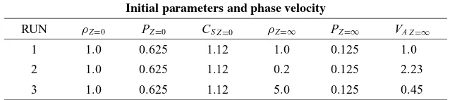
In the modeling of the plasma sheet evolution, the lobe/mantle plasma condition is one of the important pa-rameters, because in the near Earth’s magnetotail, the lobe is very tenuous region of plasmas which density is about 10−2 ∼ 10−1 cm−3, while in the distant magnetotail the
mantle having a cold-dense plasma with ∼1 cm−3 is
be-lieved to contact with the plasma sheet (e.g., Goslinget al., 1984). The magnetic field intensity in the lobe decrease with the distance from the Earth. Therefore, the speed of the Alfv´en waves propagating around the plasmoid decrease as it propagates downward (tailward). To understand the basic interaction between the high-speed plasma produced by the reconnection process and the original plasma sheet plasma at rest, we study the nonlinear time evolution of the plas-moid in three typical plasma parameters listed in Table 1. RUN 1 is the uniform density case, RUN 2 corresponds to the near-Earth magnetotail case where the lobe plasma den-sity is very low, and RUN 3 may be one case for the distant magnetotail with the high-density mantle plasma.
3.
Plasmoid Formation: Region Identification
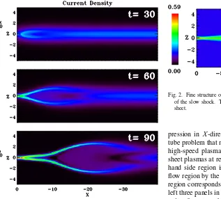
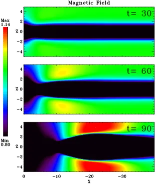
Let us study first the “plasmoid” structures for RUN 1 with the uniform plasma condition att =0. Figure 1 shows three snapshots of the electric current density JY att =30, 60, and 90. One can find that a pair of electric current lay-ers is developed from the X-type neutral point that we iden-tify later as the Petschek type slow mode shocks. As the time goes on, the current layers in the fore part of the plas-moid/magnetic island gradually curve toward the plasma sheet. The curved structure is also attributed to the slow mode shock formed by the expansion of the plasmoid/ magnetic island toward the lobe/mantle region. In the fol-lowing sections, we will argue several important regions one by one.
3.1 Near X-point region: 0>X>−20:t=120 We focus first on the plasma sheet structure in the vicinity of the X-type neutral point. Figure 2 shows the snapshot of the plasma temperature at t = 120. By checking the MHD Rankine-Hugoniot relations, we identify the boundary between the lobe and the hot plasma sheet as the slow-mode shock, and the hot plasma is mainly heated by the Petschek-type reconnection.
Fig. 1. Time evolution of the electric current structures during the early nonlinear stage of reconnectiont=30, 60, and 90: Current layer is split into a pair of thin layers att =90, these layers gradually bend around X=10.
between the outer and inner plasma sheet is a contact dis-continuity, because the plasma flow is almost along the X-axis and does not cross the interface. The thin and inner hot plasma region is thought to be produced by Joule-heating around the X-type neutral point.
The similar plasma structure has been observed by the Geotail satellite, and the inner and outer plasma sheet struc-ture has been discussed by Hoshino et al. (2000). They discussed that two discontinuities exist during magnetic re-connection in the magnetotail: one is the slow-mode shock, and the other is the contact discontinuity which separates the slow shock heated plasmas from the isotropic plasmas in the inner plasma sheet.
3.2 Inner plasmoid structure: −30>X>−60: t= 140
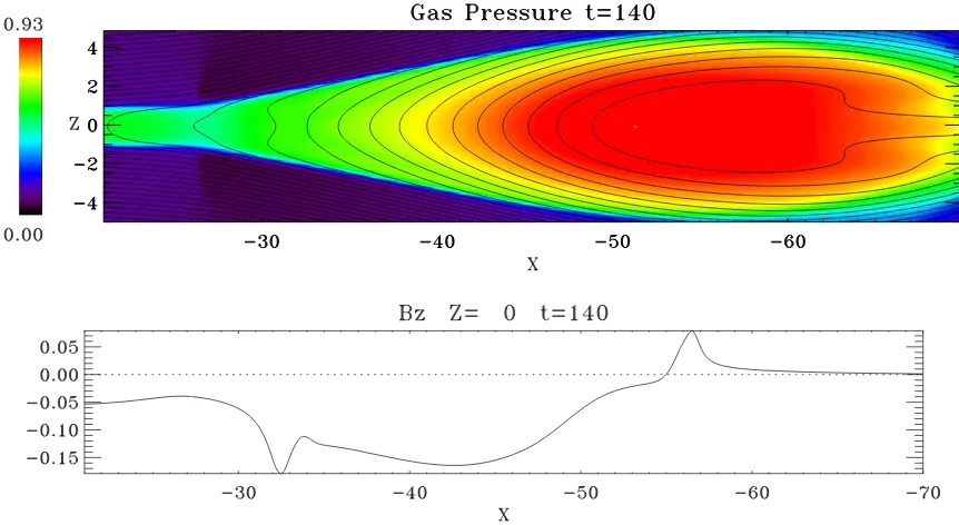
Next, we examine the inner structures of the magnetic island surrounded by the enhanced electric current layer. The top panel of Fig. 3 shows the color contour plot of the plasma gas pressure in the region from X = −20 to−70 att = 140, and the magnetic field lines are superimposed onto the color contour. The bottom panel displays the slice of BZ along the X-axis. We can find that the gas pressure and the Z-component of the magnetic field are simultane-ously enhanced inside the plasmoid/magnetic island around
X ∼ −50. The plasma parameters change gradually across
X ∼ −50, and the boundary is not sharp, but it can be iden-tified as the tangential discontinuity. The regionX >−50 is occupied with the accelerated plasma by reconnection that were the lobe plasma before reconnection.
In order to understand the property of the plasma
com-Fig. 2. Fine structure of the plasma temperature in the downstream region of the slow shock. This hot plasma region is embedded in the plasma sheet.
pression in X-direction, we study one dimensional shock tube problem that mimics the interaction of the accelerated, high-speed plasma flow by reconnection with the plasma sheet plasmas at rest. In our shock tube modeling, the left-hand side region is assumed to be the high-speed plasma flow region by the reconnection outflow, and the right-hand region corresponds to the original plasma sheet at rest. The left three panels in Fig. 4 show the initial state of a disconti-nuity: from top, the plasma flow velocity, the gas pressure, the magnetic field BZ, and the plasma density. As the time
goes on, the initial discontinuity develops into one pair of the fast-mode shocks and a tangential discontinuity. Due to the compression of high-speed plasma flow ejected from the left-hand boundary, the magnetic fields are intensified be-hind the tangential discontinuity (we call this region as Re-gion I). In ReRe-gion I, the plasmas are occupied by the accel-erated plasma originated from the lobe, while in front of the tangential discontinuity the plasmas belong to the plasma sheet plasma existing before the reconnection onset (we call this region as Region II). In Region II, the plasma is com-pressed, but noBZ magnetic field exists. The above numer-ical Riemann solution can be also analytnumer-ically solved, and we obtained the consistent result.
The shock tube solution can be compared with the simulaton result in Fig. 4. Tangential discontinuity is formed at X ∼ −50 and almost no BZ magnetic field exist in
forward-side of the plasmoid/magnetic island in the neutral line.
Since the propagation speed of the tangential disconti-nuity is slower than the speed of the reconnection outflow ejected from the X-type region, the reconnecting magnetic field lines should be piled up behind the tangential discon-tinuity. If the outflow exceeds the fast-mode speed, another discontinuity, as the fast reversed shock, should be formed between the reconnection outflow region and the com-pressed plasma region behind the tangential discontinuity. From the magnetic field plot in Fig. 3, we can find the reverse shock around X ∼ −32 as the boundary of the pile up magnetic field. Whether or not the outflow speed exceeds the fast mode speed depends on the lobe plasma situation. According to the standard reconnection model, the outflow velocity becomes almost the Alfv´en velocity of
BZ=∞/√ρZ=∞in a strong slow shock limit. The lobe
neu-Fig. 3. Plasmoid Structure att=140: Top panel shows the gas pressure and the magnetic field lines around the plasmoid. Bottom panel shows the profile ofBZon the neutral line. This reconnecting magnetic field lines accumurate into the plasmoid, and the high gas pressure region is formed behind the
accumurated magnetic field region. This boundary is identified as the tangential discontinuity.
Fig. 4. A shock tube problem that mimics the plasmoid inner structure along the neutral line: Left-hand panel shows the initial conditions and right-hand panel is the snapshot att=10. These initial discontinuities are separated into three MHD discontinuities. We can observe that the tangential disconti-nuity atX= −12 and a pair of fast mode shocks are formed. Region I corresponds to the left-hand side region of the tangential discontinuity and there intensified magnetic field.
Fig. 6. Electric current and magnetic field lines att =140. The slow-mode Rankine-Hugoniot conditions are checked for the regions denoted by the number 1 to 6.
Fig. 7. Magetic field strength enhances in the lobe in association with the plasmoid formation.
tral sheet, then ρZ=0TZ=0 = PZ=0 = BZ2=∞/2.
There-fore, the Mach numberMof the outflow plasma isM2 =
(2/γ )(ρZ=0/ρZ=∞) where we assume that the magnetic
field is weak in the outflow region. Although this is a very rough estimation, we could expect the formation of the re-verse shock in the outflow region when the lobe density is smaller than the plasma sheet density.
Figure 5 shows the contour of theVX and the flow vector att = 140. The sharp discontinuity of the plasma veloc-ity is formed at aroundX = −30, and we can also observe the kink of the plasmoid/magnetic island boundary in the
contour plot ofVX around X = −25. We think that this
re-gion is produced due to the fast-mode compressional waves propagating backward from the plasmoid/magnetic island, and that both the discontinuity of velocity and the kink also correspond to the position of the fast mode wavefront (FWF) expected in the shock tube modeling.
The kink position in the current layer X = −25 in Fig. 5 is not same as the pile up magnetic field boundaryX = −30 in Fig. 3, because the outflow plasma is not uniform in the
Fig. 8. Magnetic-field lines show drastic kink at the intermediate shock att=190.
region sandwiched between the slow shock and the contact discontinuity. Therefore, the reverse shock front starts to bend, and forms a concave shape front.
The forward of the compressional FWF which is expected in shock tube situation, however, can hardly be observed in Fig. 5. Since the plasma flow in two dimensional system expands into the lobe region, and the amplitude of the com-pressional FWF becomes weak as it propagates. We must take into account the effect of plasma expansion to get bet-ter modeling of the fast mode wave properties.
3.3 Plasmoid boundary region:X>−70:t=140
We discuss here the intensified and curved electric current layer surrounding the plasmoid/magnetic island. It is known that one pair of the slow-mode shocks is formed during mag-netic reconnection in Petschek steady-state model, and we can confirm that the slow shock pair is formed around the X-type region in our simulation result. The enhanced elec-tric current layer extends further downstream in such a way that the current layer surrounds the plasmoid/magnetic is-land. We check whether or not every each point on this cur-rent layer satisfies the slow shock jump conditions, and we confirm that the boundary between the plasmoid/magnetic island and the lobe is the slow-mode shock. The numbers indicated in Fig. 6 show the positions that we examine the slow shock Ranikine-Hugoniot relations. The Mach num-ber, the shock angle between the shock normal and the mag-netic field, the plasma beta in upper-region of each region are listed in Table 2.
The slow-mode Mach number along the slow shock from the X-type neutral point to the kink position around X =
−25 is about 1.85, which is almost constant. However, across the kink structure of the plasmoid/magnetic island, we find that the slow mode Mach numberM1 changes
dis-continuously from 1.85 (position 1) to 2.34 (position 2).
Table 2. Identification of the slow shock: Xand Zshow the positions that we examine the Rankine-Hugoniot relations, Mach numberM1, the angle between the shock normal and the magnetic fieldθB N1, the
plasma betaβ1in the shock upstream region.
Slow shock
No. X Z M1 θB N1 β1
1 −24.2 0.93 1.85 87.4 0.18
2 −26.9 1.06 2.34 88.6 0.10
3 −41.2 3.42 2.28 86.5 0.07
4 −51.9 4.60 1.81 87.4 0.13
5 −56.6 4.60 1.50 87.2 0.26
6 −60.9 4.31 1.30 87.7 0.39
As further going downward along the slow shock layer, the slow Mach number M1 in the upstream region gradually
decreases. Beyond the position of the number 6, the slow shock identification becomes difficult becauseM1becomes
close to unity.
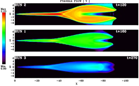
Fig. 9. Dependence on the initial lobe density of the plasmoid structure: Top RUN 2 (Vmax ∼2.23), Center RUN 1 (Vmax ∼ 1.00), Bottom RUN 3 (Vmax∼0.46), color bar is log-scaled.
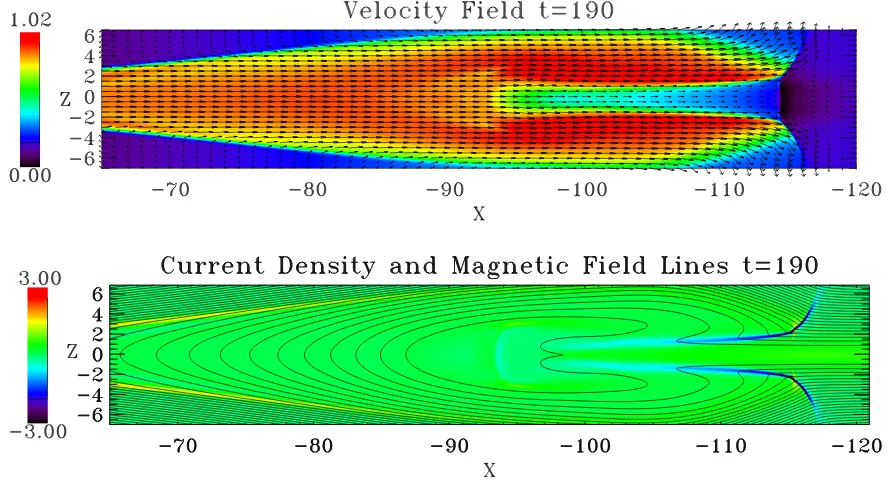
3.4 Forward-side structure of the plasmoid: −105> X>−115:t=190
The top panel of the Fig. 8 showsVX superimposed with
the plasma flow vector att =190, and the bottom shows the strength of the current density superimposed with the mag-netic field lines. On the top figure, one can observe that the plasma flow velocity near the neutral sheet is much slower than the outer plasma flow from X = −95 to −115. It seems that the outflow plasma cannot enter into the center of the plasmoid/magnetic island, because the plasma sheet consists of the high density plasma with a large inertia.
In the region between the slow flow and the fast flow in the plasma sheet on the front-side of the plasmoid/magnetic island X = −95 ∼ −115, we find another shock that the magnetic field reverse its tangential component. The region corresponds to the blue color region on the current den-sity plot in Fig. 8. By checking the Rankine-Hugoniot re-lations across the boundary, we can identify the region as the intermediate shock, (e.g., Wu, 1987; Hau and Sonnerup, 1989). The upstream region is the forward region of the plasmoid/magnetic island where the plasma flow is slow. The wave-front of the intermediate shock is thought to cor-respond to the inner edge of the “crab-hand” shaped plas-moid/magnetic island.
4.
Dependence on Lobe Density Profile
We analyzed the simulation result RUN 1 in the previ-ous section and understood the formation process of several important structures embeded in the plasmoid/magnetic is-land. In this section, we discuss how the plasmoid evolu-tion is modified by the lobe plasma condievolu-tion (see Table 1). We compare three simulation RUN 1, 2, and 3 in Fig. 9.
From the top to the bottom, RUN 2 with the low plasma density case att =0, RUN 1 with the uniform plasma den-sity case, and RUN 3 with the high-denden-sity plasma in the mantle/lobe are shown. Note that the plasma sheet condi-tions are same for RUN 1, 2, and 3. Each snapshot is taken when the front-face of the plasmoid/magnetic island reaches almost the same X-position in the simulation box.
The region behind the tangential discontinuity is occupied with the hotter and denser plasmas than the lobe plasmas, except for the vicinity of the neutral line. We can find that plasmas are accelerated to Alfv´en velocity defined in the lobe, and the speed of plasmoid/magnetic island propagation is about a half of the Alfv´en velocity. The outside bound-ary surrounding the plasmoid/magnetic island is curved into the plasma sheet, and we also confirm that these boundaries are the slow-mode shock. These properties are common among RUN 1, 2, and 3. Around the front region of the plasmoid/magnetic island, however, the plasmoid expansion into the lobe is different, and the “crab-hand” shaped struc-ture is no longer observed in the high-density lobe case of RUN 3.
com-Let us study the opening angle of the slow-mode shocks and the inner-edge structure of the plasmoid/magnetic is-land. In the low lobe density case of RUN 2, the plas-moid/magnetic island can expand wider toward the lobe, and the reconnection outflow plasma can hardly penetrate into the center of the plasmoid/magnetic island. The plasma di-vergence causes the deformation of magnetic field topology of inner-edge of the plasmoid/magnetic island, and the inter-mediate shocks can develop. This behavior is well observed in the low plasma density case.
In case of the high-density lobe for RUN 3 as shown in Fig. 9, the crab-hand shape is not well developed, and the intermediate shock no longer appears inside the plasmoid/ magnetic island. However, in front of the plasmoid/mag-netic islandX ∼ −90, we can find the bow shock type struc-ture produced by the tailward propagation of plasmoid/mag-netic island. This front boundary has the intermediate shock behavior because the magnetic field polarity is changed and because the plasma is compressed.
5.
Summary
We have studied the nonlinear evolution of plasmoid/ magnetic island by using the high-resolution, 2-D MHD simulation code, and have discussed how the lobe/mantle plasma affects on the plasmoid/magnetic island dynamic structure.
Once the reconnection triggered by the localized resistiv-ity on an X-type neutral point, the Petschek-type slow-mode shock is formed, and the fast-mode rarefaction wave propa-gates toward the lobe in its upstream region. The lobe mas are convected down to the plasma sheet, and the plas-mas can be heated by the slow shock. Further downstream, we find the higher temperature regions where the plasmas are heated by the magnetic diffusion process around the X-type neutral point. The interface between the shock heated plasma and the Joule-heated plasma sheet can be recognized as the contact discontinuity. These outflow plasmas are ac-celerated to the nearly Alfv´en velocity defined in the lobe, and they collide with the original plasmas at rest and com-press the surrounding medium. Therefore, the tangential discontinuity is formed so as to separate the original plasma sheet plasmas from the reconnection accelerated plasmas, and the magnetic field starts to pile up behind the tangential discontinuity. The structure inside the compressed region depends on the lobe plasma condition. In case of the low lobe density, the “crab-hand” shaped structure is formed in the front region of the plasmoid/magnetic island, and the in-terface develops into the intermediate shock.
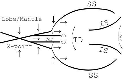
In summary, five kinds of structures could be observed in plasmoid/magnetic island: 1) the Petschek-type slow-mode
Fig. 10. Summary of our results.
shocks around the reconnection region, 2) the Joule heated plasmas region inside the contact discontinuities down-stream the slow-mode shocks, 3) the tangential discontinu-ity inside the plasmoid, 4) the expanding slow shocks which propagate downward, 5) the intermediate shocks formed in front-side of the plasmoid. The above structures are summa-rized in Fig. 10.
References
Birn, J. and M. Hesse, MHD simulations of magnetic reconnection in a skewed three-dimensional tail configuration,J. Geophys. Res.,96, 23– 34, 1991.
Feldman, W. C., R. L. Tokar, J. Birn, E. W. Hones, Jr., S. J. Bame, and C. T. Russell, Structure of a slow mode shock observed in the plasma sheet boundary layer,J. Geophys. Res.,92, 83–94, 1987.
Gosling, J. T., D. N. Baker, S. J. Bame, E. W. Hones, Jr., D. J. McComas, R. D. Zwickl, J. A. Slavin, E. J. Smith, and B. T. Tsurutani, Plasma entry into the distant tail lobes: ISEE-3,Geophys. Res. Lett.,11, 1078–1081, 1984.
Hau, L. N. and B. U. O. Sonnerup, On the structure of resistive MHD in-termediate shocks,J. Geophys. Res.,94, 6539–6551, 1989.
Hesse, M. and J. Birn, On dipolarization and its relation to the substorm surrent wedge,J. Geophys. Res.,96, 19,417–19,426, 1991.
Hones, E. W., Jr., Substorm processes in the magnetotail: Comments on ‘On hot tenous plasma, fireballs, and boundary layers in the Earth’s mag-netotail’ by L. A. Frank, K. L. Ackerson, and R. P. Lepping,J. Geophys. Res.,82, 5633, 1977.
Hoshino, M., T. Mukai, I. Shinohara, Y. Saito, and S. Kokubun, Slow shock downstream structure in the magnetotail,J. Geophys. Res.,105, 337– 347, 2000.
Ieda, A., S. Machida, T. Mukai, Y. Saito, T. Yamamoto, A. Nishida, T. Terasawa, and S. Kokubun, Statistical analysis of the plasmoid evolution with Geotail observations,J. Geophys. Res.,103, 4453–4465, 1998. Machida, S., T. Mukai, Y. Saito, T. Obara, T. Yamamoto, A. Nishida, M.
Hirahara, T. Terasawa, and S. Kokubun, GEOTAIL low energy partical and magnetic field observations of a plasmoid atXG S M = −142RE, Geophys. Res. Lett.,21, 2995–2998, 1994.
Otto, A., K. Schindler, and J. Birn, Quantitative study of the nonlinear for-mation and acceleration of plasmoids in the Earth’s magnetotail,J. Geo-phys. Res.,95, 15,023–15,037, 1990.
Petschek, H. E., Magnetic field annihilation,NASA Spac. Publ., 425–439, 1964.
Saito, Y., T. Mukai, T. Terasawa, A. Nishida, S. Machida, M. Hirahara, K. Maezawa, S. Kokubun, and T. Yamamoto, Slow-mode shocks in the magnetotail,J. Geophys. Res.,100, 23,567–23,581, 1995.
Sato, T. and T. Hayashi, Externally driven magnetic reconnection and pow-erful magnetic energy converter,Phys. Fluid,22, 1189–1202, 1979. Scholer, M. and D. Roth, A simulation study on reconnection and
small-scale plasmoid formation,J. Geophys. Res.,92, 3223–3233, 1987. Seon, J., L. A. Frank, W. R. Paterson, J. D. Scudder, F. V. Coroniti, S.
Slavin, J. A., E. J. Smith, B. T. Tsurutani, D. G. Sibeck, H. J. Singer, D. N. Baker, J. T. Gosling, E. W. Hones, and F. L. Scarf, Substorm-associated traveling compression regions in the distant tail: ISEE 3 observations,
Geophys. Res. Lett.,11, 657, 1984.
Terasawa, T., H. Kawano, I. Shinohara, T. Mukai, Y. Saito, M. Hoshino, A. Nishida, S. Machida, T. Nagai, T. Yamamoto, and S. Kokubun, On the determination of a moving MHD structure: Minimization of the residue of integrated Faraday’s equation,J. Geomag. Geoelectr.,48, 603–614, 1996.
Ugai, M. and T. Tsuda, Magnetic field-line reconnexion by localized
en-hancement of resistivity. Part 1. Evolution in a compressible MHD fluid,
J. Plasma Phys.,17, 337–356, 1977.
Whang, Y. C., D. Fairfield, E. J. Smith, R. P. Lepping, S. Kokubun, and Y. Saito, Observations of double discontinuities in the magnetotail, Geo-phys. Res. Lett.,24, 3153–3156, 1997.
Wu, C. C., On MHD intermediate shocks,Geophys. Res. Lett.,14, 668– 671, 1987.