Scholarship@Western
Scholarship@Western
Electronic Thesis and Dissertation Repository
9-18-2012 12:00 AM
Simultaneous particle agglomeration and attrition in a high
Simultaneous particle agglomeration and attrition in a high
temperature fluidized bed
temperature fluidized bed
Mithun Saha
The University of Western Ontario
Supervisor
Professor Franco Berruti
The University of Western Ontario Joint Supervisor Professor Cedric Briens
The University of Western Ontario
Graduate Program in Chemical and Biochemical Engineering
A thesis submitted in partial fulfillment of the requirements for the degree in Master of Engineering Science
© Mithun Saha 2012
Follow this and additional works at: https://ir.lib.uwo.ca/etd
Part of the Petroleum Engineering Commons
Recommended Citation Recommended Citation
Saha, Mithun, "Simultaneous particle agglomeration and attrition in a high temperature fluidized bed" (2012). Electronic Thesis and Dissertation Repository. 876.
https://ir.lib.uwo.ca/etd/876
This Dissertation/Thesis is brought to you for free and open access by Scholarship@Western. It has been accepted for inclusion in Electronic Thesis and Dissertation Repository by an authorized administrator of
SIMULTANEOUS PARTICLE AGGLOMERATION AND ATTRITION IN A HIGH TEMPERATURE FLUIDIZED BED
(Spine title: Simultaneous agglomeration and attrition in a high temperature fluidized bed)
(Thesis format: Integrated Article)
by
Mithun Saha
Graduate Program
in
Department of Chemical and Biochemical Engineering
A thesis submitted in partial fulfillment of the requirements for the degree of
Master of Engineering Science
The School of Graduate and Postdoctoral Studies The University of Western Ontario
London, Ontario, Canada
ii
THE UNIVERSITY OF WESTERN ONTARIO School of Graduate and Postdoctoral Studies
CERTIFICATE OF EXAMINATION
Joint Supervisor
______________________________ Dr.Cedric Briens
Joint Supervisor
______________________________ Dr. Franco Berruti
Examiners
______________________________ Dr. Jesse Zhu
______________________________ Dr. Shahzad Barghi
______________________________ Dr. George Knopf
The thesis by
Mithun Saha
entitled:
Simultaneous particle agglomeration and attrition in a high
temperature fluidized bed
is accepted in partial fulfillment of the requirements for the degree of Master of Engineering Science
iii
Abstract
Fluid CokingTM is a major refining process to upgrade heavy crude oil or bitumen from
oil sands. In Fluid CokingTM bitumen is atomized with steam and sprayed inside a high
temperature fluidized bed of coke particles where it thermally cracks into smaller
molecules. Fluid CokingTM is a carbon rejection process as solid carbon residues are
formed during fragmentation into lighter hydrocarbon vapors. New coke deposits over
existing coke particles and, consequently, the particle size increases. In addition, particles
agglomeration occurs when the injected liquid does not disperse uniformly on individual
hot coke particles but reaches, instead, local concentrations sufficiently large to act as a
binder for several solid particles. Attrition nozzles are used to control the particle size to
maintain the desired flow properties and reactor operability. In fact, fluidization quality
degrades while there are too many particles smaller than 50 µm or larger than 600 µm.
Some of the large agglomerates may interact with the stripper sheds near at the bottom of
Fluid CokersTM, resulting in their fouling and can cause premature reactor shut down.
The simultaneous particle agglomeration and attrition observed in Fluid CokersTM has
been simulated at elevated temperature in laboratory scale fluidized unit to study these
processes and to develop and apply new technological solutions to reduce the generation
of large agglomerates. An experimental technique has been developed to simultaneously
perform the spray injection and attrition processes utilizing different nozzle designs and
operating conditions, measuring, the initial and the final bed particle size distribution.
Various interactions of spray and attrition jets have been tested and a novel liquid
dispersion technique has been proposed and studied to reduce the production of large
agglomerates.
The results show that, when an attrition jet hits at the base of a spray jet, the formation of
large agglomerates is significantly reduced, but a large amount of unwanted fines is then
generated. On the other hand, the application of satellite jets at the periphery of spray jets
achieved better control of large agglomerates while minimizing fines generation.
Keywords: Fluid CokerTM, Fluidized bed, High Temperature, Spray nozzle,
iv
Co-Authorship
Chapter 2
Article Title:
Study of simultaneous particle agglomeration and attrition in a high temperature fluidized bed
Authors:
Mithun Saha, Mehran Soleimani, Cedric Briens, Franco Berruti, Jennifer McMillan
Status:
Unpublished
Contributions:
Mithun Saha conducted all experimental work, data analysis and writing. Mehran Solemani assisted with setting up the fluidized bed, also assisted in some of the experimental work. Cedric Briens and Franco Berruti provided guidance, supervision and revised drafts of the work.
Chapter 3
Article Title:
Effect of different spray and attrition jet interaction in a high temperature fluidized bed
Authors:
Mithun Saha, Tarek J. Jamaleddine, Cedric Briens, Franco Berruti, Jennifer McMillan
Status:
Unpublished
Contributions:
Mithun Saha conducted all experimental work, data analysis and writing. Tarek J. Jamaleddine provided general guidance. Cedric Briens and Franco Berruti provided guidance, supervision and revised drafts of the work.
Chapter 4
Article Title:
Application of satellite jets with spray nozzle in a high temperature fluidized bed
Authors:
Mithun Saha, Tarek J. Jamaleddine, Cedric Briens, Franco Berruti, Jennifer McMillan
Status:
Unpublished
Contributions:
v
Acknowledgements
I would like to thank my supervisors Dr. Cedric Briens and Dr. Franco Berruti for their
encouragement, support and guidance. Without their inspiration and mentorship, it would
not have been possible to complete this research work and this thesis.
Financial support from Syncrude Canada is gratefully acknowledged. I would also like to
thank Dr. Jennifer McMillan for her technical guidance and support with my research
project. I would especially like to thank Dr. Mehran Soleimani and Dr. Tarek J.
Jamaleddine, post-doctoral fellows of ICFAR for providing me with valuable advice and
guidance in my experimental work.
Special thanks to Rob Taylor and Thomas Johnston for all of their help with my
experimental equipment. Thanks to University Machine Shop, Electronics Shop and the
Information and Technology Group for their assistance during my research. I would also
like to mention my appreciation to Faculty and Staff members of the Department of
Chemical and Biochemical Engineering.
I would like to thank all of the members in ICFAR for their friendship and support
throughout my graduate study.
Finally, I would especially like to thank my family members who always supported and
vi
Table of Contents
CERTIFICATE OF EXAMINATION ... ii
Abstract ... iii
Co-Authorship ... iv
Acknowledgements ... v
Table of Contents ... vi
List of Tables ... ix
List of Figures ... x
Chapter 1: Introduction ... 1
1.1 Present thesis work ... 1
1.2 Canadian oil sands development and Fluid cokingTM process ... 1
1.3 Particle agglomeration and attrition in fluidized beds- Literature Review ... 5
1.3.1 Liquid injection and agglomeration ... 5
1.3.2 Gas jet and particle attrition ... 8
1.4 Research objectives ... 9
1.5 References ... 10
Chapter 2: Study of simultaneous particle agglomeration and attrition in a high temperature fluidized bed ... 13
2.1 Abstract ... 13
2.2 Introduction ... 14
2.3 Experimental setup and methodology ... 15
2.4 Results and discussions: ... 21
2.4.1 Impact of simultaneous spray and attrition jets on macro-agglomerates formation ... 21
vii
2.4.3 Impact of simultaneous spray and attrition jets on fines generation ... 23
2.5 Conclusions ... 28
2.6 Nomenclature ... 28
2.7 References ... 29
Chapter 3: Effect of different spray and attrition jet interaction in a high temperature fluidized bed ... 30
3.1 Abstract ... 30
3.2 Introduction ... 30
3.3 Experimental setup and methodology ... 32
3.4 Results and discussion ... 41
3.4.1 Impact of spray and attrition jets interaction on macro-agglomerates formation ... 43
3.4.2 Impact of spray and attrition jets interaction on micro-agglomerates formation ... 44
3.4.3 Impact of spray and attrition jets interaction on the Sauter-mean diameter of bed particles and on the production of fines ... 45
3.5 Conclusion ... 53
3.6 Nomenclature ... 53
3.7 References ... 54
Chapter 4: Application of satellite jets with spray nozzle in a high temperature fluidized bed ... 56
4.1 Abstract ... 56
4.2 Introduction ... 56
4.3 Experimental setup and methodology ... 58
4.4 Results and discussion ... 63
4.4.1 Impact of peripheral gas jets on macro-agglomerates formation ... 64
viii
4.4.3 Impact of peripheral gas jets on bed fine particles generation ... 65
4.5 Conclusion ... 70
4.6 Nomenclature ... 70
4.7 References ... 71
Chapter 5: Conclusions and Recommendations ... 73
5.1 Conclusions ... 73
5.2 Recommendations ... 74
Appendix A ... 75
Appendix B ... 78
ix
List of Tables
Table 3.1: Total cyclone catch mass (wt % of bed mass) for only N2 gas injection through
attrition and spray nozzles ... 41
Table 3.2: Nitrogen gas consumption rate (g/s) with spray and attrition nozzles ... 42
Table 3.3: Superficial gas velocity in the upper bed region and the freeboard for various
bed operating conditions ... 42
Table 4.1: Operating conditions with 1.2 mm spray nozzle and 0.13 mm satellite nozzles
combination ... 62
Table 4.2: Operating conditions with 2.7 mm spray nozzle and 0.4 mm satellite nozzles
x
List of Figures
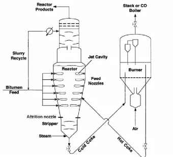
Figure 1. 1: Flow diagram of the Fluid CokingTM Process (House et. al., 2007) ... 3
Figure 1. 2: Schematic of agglomeration process. (i) Wetting and nucleation, (ii)
consolidation and coalescence and (iii) attrition and breakage (Adopted from Iveson et
al., 2001) ... 7
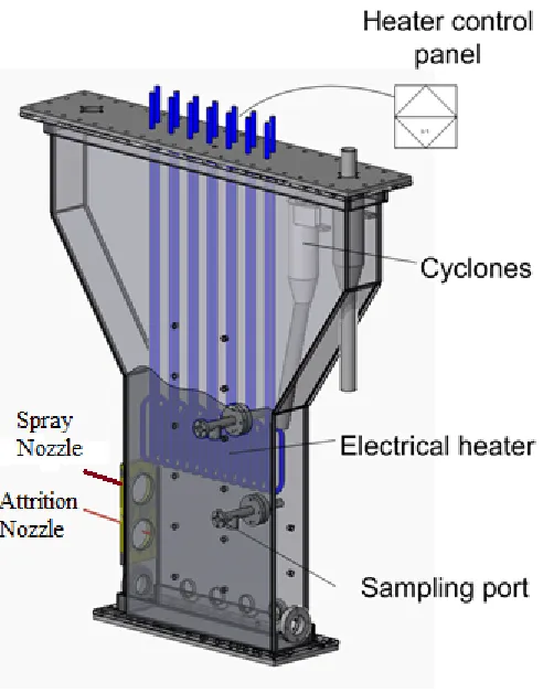
Figure 2. 1: Schematic of the high temperature fluidized bed with spray and attrition
nozzles. (Modified from Feng, 2010) 16
Figure 2. 2: Spray nozzle setup for the fluidized bed ... 17
Figure 2. 3: Layout of the straight cylindrical spray nozzle (I.D. 2.7 mm and 3.6 mm) .. 17
Figure 2. 4: Typical convergent-divergent nozzle (Throat diameters: 1.7 and 2.4 mm) .. 18
Figure 2. 5: Attrition gas flow rate with attrition pressure ... 18
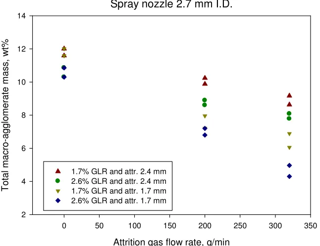
Figure 2. 6: Total macro-agglomerate mass as a function of attrition gas flow rate for
spray nozzle 2.7 mm ... 23
Figure 2. 7: Total macro-agglomerate mass as a function of attrition gas flow rate for
spray nozzle 3.6 mm ... 24
Figure 2. 8: Samples of bed particles after simultaneous agglomeration and attrition at
GLR 1.7% with 2.7 mm spray nozzle and attrition nozzle with 2.4 mm at 0.62 MPa (a)
particles size 0.85 - 1.4 mm (b) particles size 1.4 - 2.36 mm ... 24
Figure 2. 9: Micro-agglomerate mass as a function of attrition gas flow rate for spray
nozzle 2.7 mm ... 25
Figure 2. 10: Micro-agglomerate mass as a function of attrition gas flow rate for spray
xi
Figure 2. 11: Sauter-mean diameter of bed particles (45 µm < dp < 0.85 mm) as a function
of attrition gas flow rate for spray nozzle 2.7 mm ... 26
Figure 2. 12: Sauter-mean diameter of bed particles (45 µm < dp < 0.85 mm) as a function of attrition gas flow rate for spray nozzle 3.6 mm ... 26
Figure 2. 13: Fines (dp > 45 µm) mass as a function of attrition gas flow rate for spray nozzle 2.7 mm ... 27
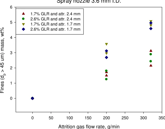
Figure 2. 14: Fines (dp > 45 µm) mass as a function of attrition gas flow rate for spray nozzle 3.6 mm ... 27
Figure 3. 1: Schematic of the high temperature fluidized bed with spray and attrition nozzle. (Modified from Feng, 2010) 34 Figure 3. 2: TEB spray nozzle (Throat diameter 2.7 mm) ... 35
Figure 3. 3: Schematic of pre-mixer for 2.7 mm TEB nozzle ... 35
Figure 3. 4: Spray nozzle setup for the fluidized bed ... 35
Figure 3. 5: Attrition nozzle (Throat diameter 1.7 mm) ... 36
Figure 3. 6: Schematic of spray and attrition nozzle positions in fluidized bed ... 37
Figure 3. 7: Macro-agglomerate mass (wt%) as a function of GLR (wt%) for spray only condition ... 47
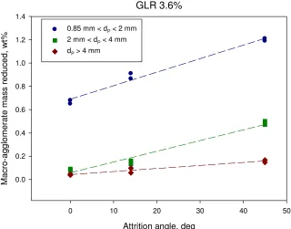
Figure 3. 8: Total macro-agglomerate mass reduced (wt %) from spray only condition as a function of attrition angle ... 47
Figure 3. 9: Macro-agglomerate mass reduced from spray only condition for GLR 3.6% as a function of attrition angle ... 48
xii
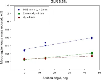
Figure 3. 11: Macro-agglomerate mass reduced from spray only condition for GLR 5.5%
as a function of attrition angle ... 49
Figure 3. 12: Micro-agglomerate mass (wt% of total bed mass) as a function of GLR
(wt%) for spray only condition, i.e. in the absence of attrition nozzles... 49
Figure 3. 13: Increase in the total mass of micro-agglomerates, relative to the increase
observed in the absence of attrition nozzles... 50
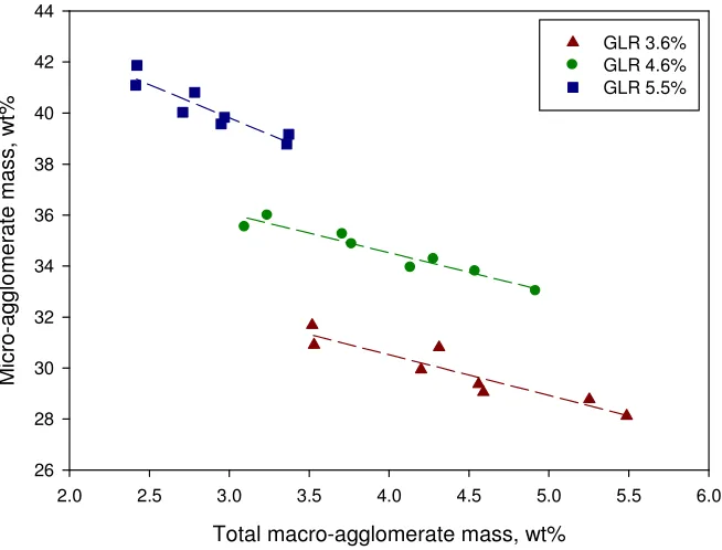
Figure 3. 14: Total macro-agglomerate mass (wt %) vs. micro-agglomerate mass (wt %)
... 50
Figure 3. 15: Reduction in the mass of fines and changes in the SMD of the bed particles
(45 µm < dp < 0.85 mm) as a function of GLR for spray only condition ... 51
Figure 3. 16: SMD of bed particles (45 µm < dp < 0.85 mm) change ratio as a function of
attrition angle ... 51
Figure 3. 17: Fines (dp < 45 µm) mass generated as a function of attrition angle ... 52
Figure 3. 18: Total macro-agglomerate mass (wt %) vs. SMD of bed particles (45 µm <
dp < 0.85 mm) ... 52
Figure 4. 1: Schematic of the high temperature fluidized bed with spray nozzle. (Modified
from Feng, 2010) 59
Figure 4. 2: TEB spray nozzle used for experiments (Throat diameter 1.2 and 2.7 mm). 59
Figure 4. 3: Satellite nozzles (0.13 mm) mounted with 1.2 mm TEB spray nozzle ... 60
Figure 4. 4: Satellite nozzles (0.4 mm) mounted with 2.7 mm TEB spray nozzle ... 60
Figure 4. 5: Total macro-agglomerate mass (wt %) as a function of total GLR (wt %) for
xiii
Figure 4. 6: Macro-agglomerate mass reduction with various size cuts for combination of
TEB 1.2 mm and Satellite 0.13 mm nozzles from macro-agglomerates mass with TEB 1.2
mm ... 66
Figure 4. 7: Macro-agglomerate mass reduction with various size cuts for combination of
TEB nozzle 2.7 mm and Satellite 0.4 mm nozzles from macro-agglomerate mass with
TEB 2.7 mm ... 67
Figure 4. 8: Micro-agglomerate mass (wt %) as a function of total GLR (wt %) for
various spray nozzles ... 67
Figure 4. 9: Total macro-agglomerate mass (wt %) as a function of micro-agglomerate
mass (wt %) for various spray nozzles... 68
Figure 4. 10: SMD of bed particles (45 µm < dp < 0.85 mm) as a function of total GLR
(wt %) for various spray nozzle ... 68
Figure 4. 11: Total macro-agglomerate mass (wt%) vs. SMD of bed particles (45 µm < dp
< 0.85 mm) with various spray nozzles ... 69
Chapter 1:
Introduction
1.1 Present thesis work
The research work presented in this thesis deals with experimental studies on particle
agglomeration and attrition in a high temperature fluidized bed with gas-liquid injection.
Fluidized beds are used for particulate operations in numerous industrial applications due
to good solid and gas mixing. Better mixing of solid and gas promote better heat and
mass distribution in a fluidized bed, which are critically important characteristic features
required by the heavy crude oil upgrading process. The Fluid CokingTM process is used
for upgrading heavy hydrocarbons streams in refineries and bitumen extracted from the
oil sands. The heavy oil or bitumen are atomized with steam and sprayed inside a high
temperature fluidized bed of circulating coke particles. When bitumen droplets come in
contact with coke particles, a significant portion of droplets form agglomerates with coke
particles. The motivation and objective of this thesis is to achieve a better understanding
and control over the agglomerate formation process and, to improve the liquid feed
distribution and mixing in Fluid CokingTM processes.
In this chapter, a brief description of Canadian oil sands development and of Fluid
CokingTM process will be presented first. A review of recent studies on agglomeration
formation and breakage will follow. This chapter concludes with the specific objectives
of the research work.
1.2 Canadian oil sands development and Fluid cokingTM process
Canada has a vast deposit of heavy oil in the province of Alberta. This heavy oil is a tar
like petroleum crude available in the form of a mixture of water, sand, clay and bitumen
which is typically referred to as “oil sand”. Most of this petroleum resource is located in
the Athabasca region of Northeastern Alberta. The estimated reserve of Alberta oil sands
technologies. With this amount of recoverable oil, Canada rank 2nd in terms of available
oil resources, just after Saudi Arabia (Government of Alberta, 2009). Oil sands
production is different from conventional oil production. The oil deposits within about
100 meters from the surface are extracted by surface mining. For the deeper deposits, the
technology applied is known as steam assisted gravity drainage (SAGD), where steam is
injected to heat up the bitumen and reduce its viscosity so that it can be collected using
horizontal wells and pumped to the surface. Bitumen is a black, thick like heavy crude oil
and cannot be processed in conventional refining equipment. It requires a primary
upgrading process to convert it into a so-called synthetic crude oil (SCO) before it can be
further processed to produce the typical petroleum products of a refinery (waxes,
naphtha, gasoil, gasoline, solvents, lubricants, and gaseous products).
Fluid CokingTM is a thermal cracking process and use a non-catalytic chemical reaction to
upgrade bitumen to light synthetic crude oil (Gray, 2002). In the thermal cracking
process, long chain hydrocarbons break down to smaller chain hydrocarbons at elevated
temperatures, and, in the process, reject solid carbon. Fluid CokingTM is a continuous
process developed by ExxonMobil Corporation. Currently, Fluid CokingTM process is
used by many refineries around the world to convert heavy oil and Fluid Catalytic
Cracking (FCC) bottoms to lighter crude oil fractions. Syncrude Canada is the largest
producer of synthetic oil from the thermal cracking of bitumen extracted from the oil
sands using three of the largest Fluid CokersTM in the world. Syncrude has produced 107
million barrels or 300,000 barrel per day synthetic crude in the year of 2010. They have
capacity to produce over 15 percent of Canadian crude oil demand (Syncrude Canada
Figure 1. 1: Flow diagram of the Fluid CokingTM Process (House et. al., 2007)
Figure 1.1 provides a schematic diagram of the Fluid CokingTM process. The Fluid Coker
consists of two vessels, a reactor and a regenerator or burner. The reactor has three
sections: a scrubber at the top, a reaction section in the middle, and a stripper at the
bottom. Coke particles are heated to 600-800 °C in the fluidized bed burner by burning a
fraction of the coke with air, and they are transported to upper section of rector via a hot
coke standpipe to bring the required heat to crack the feed bitumen. Feedstock bitumen,
heated to around 350 °C and atomized with steam, is sprayed into a bubbling or turbulent
fluidized bed of coke particles in the reaction section operating at 510-550 °C (House et
al., 2007) using banks of nozzles located at different axial and radial positions. As the
liquid droplets come in contact with coke particles, endothermic cracking reactions occur.
The products of these reactions are a mixture of gas, light and, heavy oil vapors, and
coke. The cracked gases and vapors pass through the scrubber section of reactor and are
the non-condensable gases. The cracking process generates gases and vapors with a
higher hydrogen-to-carbon ratio than the original feed by rejecting solid carbon which is
deposited over the existing coke particles that are circulating through the system. The
coke particles grow in size, flow downwards to the stripper section, where entrapped light
hydrocarbons are removed with steam, and are then transported to the burner for the
subsequent re-heating cycle. The most desired Fluid CokingTM products of are light and
heavy gas oils which make up the sweet crude oil. Thus the objective of the Fluid
CokingTM process is to maximize gas-oils production while minimizing lighter gases and
coke.
As described above, during the Fluid CokingTM process, the bed particles increase in size
due to new coke formation. To maintain a continuous operation and achieve the desired
mass flowrates between reactor and burner, the bed particle size needs to be within an
optimal size range. If there are too many large particles over 600 µm, slugging, bed
defluidization and plugging of the stripper section may occur (McMillan et al., 2007). On
the other hand, with excessive fine particles below 50 µm, fluidized bed behavior
becomes erratic (Dunlop et al., 1958). Therefore, the bed particle size is controlled by
attrition created by jets of high pressure superheated steam from supersonic attrition
nozzles located just above the stripper section. The attrition nozzles have a
converging-diverging section, to achieve sonic speed at the throat and supersonic speed at the nozzle
exit. High speed steam entrains and accelerates slow moving coke particles into the spray
jet cavity, and slams them over dense bed particles near the jet tip, where some of them
fracture into smaller fragments. These attrition nozzles consume a large percentage of the
total steam used in Fluid CokersTM and improvement of the attrition nozzle efficiency
would be highly desirable in terms of considerable savings in steam consumption, in the
ability to process more feed in the reactor, and in the consequent reduction in the amount
of water which would need to be condensed and separated from the produced synthetic
crude oil. It is expected that all these savings would be reflected in a significant
enhancement of the economics and environmental friendliness of the Fluid CokingTM
In addition to normal particle growth during the coking process, poor feed injection and,
consequently, poor liquid-solid contact, account for the formation and growth of larger
and wet agglomerates which hinder fluidization quality as well as mass and heat transfer
processes, leading to lower yields of desirable liquid products. In addition, these large
agglomerates, being wet and rich in hydrocarbons, cause stripper fouling which is
typically the main reason for premature reactor shutdowns. To minimize this problem, the
reactor operating temperature is kept higher than optimal, causing higher vapor phase
cracking of light and heavy gas-oils to lighter non-condensable gases resulting in lower
yields of the more valuable condensable fractions. Therefore, a better solution would be
to find ways to improve the liquid-solid contact during the interaction between feed jet
and solid bed particles, in the reactor section, resulting in a lower amount of large
agglomerates. Similarly, improvements in the effectiveness of the attrition nozzles would
result in lower steam consumption, higher yields and enhanced reactor operability. These
considerations represent the motivation for the research work reported in this thesis.
1.3 Particle agglomeration and attrition in fluidized beds- Literature Review
1.3.1 Liquid injection and agglomeration
The contact between injected liquid and solid particles in a fluidized bed was examined
by Leclere et al. (2001) by measuring the vaporization rate of injected liquid feed. They
developed a new model to predict the formation of agglomerates depending on the spray
droplet size and bed particle size. Gray et al. (2002) indentified the key factors governing
wet agglomerates behavior in a fluid cokerTM as the Stokes number of the particles, the
thickness of the liquid films and the diameter and surface roughness of the particles. They
emphasized the importance of an efficient mechanism of spraying the feed on the surface
of coke particles creating uniform thin films. The mechanism of agglomerate formation
was then studied by Ariyapadi et al. (2003) using an X-ray imaging technique with the
injection of non-evaporating radioactive liquid tracer in a fluidized bed; they reported that
a significant amount of agglomerates forms at the end of the jet cavity. House et al.
contact. They reported that the initial contact of liquid droplets with solids can be
improved by modifying the way the liquid feed jet interacts with fluidized particles.
Bruhns et al. (2004) studied the liquid injection by spraying evaporating liquid in
fluidized beds and found that agglomerates form at tip of some spray nozzles. They
injected water at a bed temperature of 153° C and the temperature profile in the jet bed
interaction region was monitored as a function of liquid evaporation rate. Ariyapadi et al.
(2004) developed a model to determine the entrainment of solids and gas into the jet
cavity formed by a spray nozzle in a fluidized bed. With injection of non-evaporating
liquid using a conventional spray nozzle, McMillan et al. (2007) studied the mixing of
liquid and solids. They found that the core of the jet cavity is a liquid rich region, while
the annular region is richer of solid particles, and that enhancing the radial mixing along
the jet cavity improves the quality of the liquid distribution. In fact, Chan et al. (2004)
proposed the implementation of a draft tube mixer positioned coaxially downstream of
the feed nozzles, which would enhance the radial mixing of liquid droplets and solid
particles. This study derived from earlier findings by Hulet et al. (2003), who investigated
the particle entrainment and the stability of the feed jet in a fluidized bed when using a
draft tube downstream of the spray nozzle. Portoghese et al. (2007) developed a nozzle
performance index measure the liquid-solid mixing characteristics of different liquid
injection nozzles. House et al. (2007) reported that higher liquid-to-solid (L/S) ratios in
the jet-bed interaction region lead to agglomeration and, consequently, to heat transfer
limitations.
Since the contact of liquid feed and solid bed particles in fluidized beds results both in the
desirable formation of distributed liquid films over individual mobile particles, and the
undesirable formation of small and large particle agglomerates, it is important to better
understand the phenomena involved during their formation.
Granulation or agglomeration is the process that binds particles together into larger
granules in which the original particles can still be distinguishable. For wet
agglomeration, a liquid binder is required. In agglomerates and granules, liquid can exists
in three forms producing cohesive forces: - (a) mobile liquid bridges, (b) adsorbed liquid
The binder viscosity has been recognized as an important parameter in controlling the
granulation behavior (Ennis, 1990).
Fundamentally there are three rate processes which determine wet granulation behavior
(Iveson et al. 2001). Schematic diagrams of these processes are shown in Figure 1.2.
Figure 1. 2: Schematic of agglomeration process. (i) Wetting and nucleation, (ii) consolidation and coalescence and (iii) attrition and breakage (Adopted from Iveson
et al., 2001)
1. Wetting and nucleation: the liquid binder is bought into contact with a dry powder
bed, and is distributed throughout the powder bed to form nuclei.
2. Consolidation and growth: collision between two granules, granules and dry
powder, granules and bed wall lead to compaction and growth.
3. Attrition and breakage: wet or dry granules break due to impact, wear or
This thesis work mainly focused on the formation of agglomerates resulting from the
simultaneous agglomeration and attrition created by various injection and attrition nozzle
configurations and operating conditions.
1.3.2 Gas jet and particle attrition
There have been extensive studies over particle attrition in fluidized beds. Most of the
research considered the turbulent jet theory developed by Abromovich (1963), De
Michelle (1976) and Xuereb (1991). A high velocity jet within a fluidized bed creates a
differential pressure between the formed low density jet cavity and the turbulent shear
layers at the jet bed interface, which draws fluidization gas towards the jet. While the
flow rate of gas is significantly high, it entrains solid particles inside the jet. Xuereb et al.
(1991) and later Felli et al. (2002) observed that particles are entrained mostly near the
nozzle tip. Ariyapadi et al. (2003) reported that particles size, density and gas properties
will affect the entrainment rate of particles.
The purpose of the application of high velocity gas jets in fluidized beds is particle
attrition. There are two modes of particle attrition: abrasion and fragmentation. With
abrasion, very fine solid elements (irregularities) are removed from the particle surface,
making the particles rounder, while keeping the particle size distribution nearly
unchanged. On the contrary, with fragmentation, particles break into smaller pieces and
the particle size distribution shifts, often to a bimodal distribution (Werther and
Rappenhagen, 1999). Patel et al. (1986) classified the variables causing particle attrition
in two categories: particle properties and fluidized bed environment. Particle properties
encompass shape, surface roughness and strength. Fluidized bed properties include
fluidization velocity, bed temperature and attrition pressure. Lin et al. (1980) investigated
elutriation and attrition in fluidized bed and found that the attrition rate is related to the
excess fluidization velocity (Ug - Umf). They reported that, in the absence of jets, the
majority of the attrition process occurs in the bubble wake due to excess fluidization
velocity and presented a correlation to estimate the rate of fines generation. Bentham et
that the breakage mechanism works by entrainment of particles from the dense phase
region surrounding of gas jet into the dilute jet cavity. The high speed gas accelerates the
entrained particles and slams them over the denser bed of particles near the jet tip. They
reported a correlation equation for attrition rate as a function of jet velocity.
In a Fluid CokerTM, high velocity jet attrition has been achieved using De-Laval type
convergent-divergent supersonic nozzles. McMillan et al. (2007) investigated the
operating parameters of attrition nozzle on particle attrition and found that larger
diameter nozzles operating at high gas flow rate with low density gases show a higher
grinding efficiencies, where the grinding efficiency is defined as the ratio of the new
particle surface that is created through attrition, to the mass of attrition gas used. Cruz et
al. (2010) studied the attrition nozzle design and found that the divergent angle of the
nozzle needs to be within the optimum range of 3° to 8°. With higher angles, shock waves
occur in the divergent section, whereas, with lower angles, higher friction at the nozzle
wall dissipates excessive energy. Li et al. (2011) studied the effects of bed temperature on
the particle attrition rate and reported that higher grinding efficacies could be achieved at
higher bed temperatures when using a high gas flow rate of low density attrition gas.
1.4 Research objectives
The overall goal of this research work was to understand the simultaneous particle
agglomeration and attrition process occurring in a high temperature fluidized bed where
liquid feed is injected and distributed over solid particles. The ultimately objective was to
reduce the large agglomerate formation in the Fluid CokingTM process by identifying and
applying novel concepts utilizing improved liquid and attrition gas injection devices and
optimal operating parameters.
The specific objective of the first study reported in the thesis was the determination of the
best operating parameters with simultaneous spray and attrition jets in a fluidized bed to
minimize production of large agglomerates. Previous studies investigated spray and
the break-up of wet agglomerates, before they solidify, was not investigated. Various
spray and attrition nozzle sizes and operating parameters were examined. In this study,
the spray and attrition nozzles did not interact directly. The generation of large
agglomerates, the Sauter-mean diameter of bed particles, and the amount of fines have
been measured to quantify the combined performance of the spray and attrition nozzles.
To optimize the attrition gas consumption rate, various gas flow rates with various nozzle
sizes have been examined. This study required the development of a new experimental
system to simulate the agglomeration and attrition processes that occur in a Fluid
CokerTM.
The objective of the second study of this thesis was the investigation of different types of
direct interaction between spray and attrition jets in a hot fluidized bed. An innovative
approach was taken to compare the conventional separate (non-interacting) spray and
attrition jets injection with attrition jets hitting the spray jet cavity at various locations.
The objective of the third study was to reduce large agglomerate formation by improving
the liquid dispersion over the fluidized bed particles. A novel nozzle design used satellite
pure gas nozzles positioned at the periphery of the feed spray jet. The satellite gas jets
enhanced particle entrainment into the spray cavity and liquid-solid mixing within the
spray jet cavity. The effect of this solution on agglomerate formation has been
investigated.
1.5 References
Abromovich, G., The theory of turbulent jets, Massachusetts: M.I.T. Press, 1963.
Ariyapadi, S., Holdsworth, D., Norley, C, Berruti, F., Briens, C, "Digital X-Ray imaging
technique to study the horizontal injection of gas-liquid jets into fluidized beds",
Int. J. Chem. React. Eng., 1 (A56), 1114 (2003).
Bentham, A., Kwan, C, Boerefijn, R., Ghadiri, M., "Fluidised-bed jet milling of
Cruz, N.; Briens, C.; Berruti, F. Supersonic attrition nozzles in gas-solid fluidized beds.
Chemical Engineering and Processing: Process Intensification 2010, 49, 225-234.
De Michele, G., Elia, A., Massimilla, L., "The interaction between jets and fluidized
beds", Ing. Chim. Ital, 12, 1976,155 - 162.
Dunlop D., Griffin, L., Moser, J., “Particle size control in fluid coking” Chem, Eng. Prog.
1958, 54, 39-43.
Felli, V., "Solids entrainment from a fluidized bed into a gas-liquid jet". MESc Thesis,
The University of Western Ontario, (2002).
Government of Alberta, Alberta’s Energy Industry (An Overview 2009);
<<http://www.energy.alberta.ca/Org/pdfs/Alberta_Energy_Overview.pdf.>>, 2009.
Gray, M. , “Fundamentals of bitumen cracking processes analogous to granulations: A
critical review”, The Canadian Journal of Chemical Engineering, 2002, 80,
393-401.
Sycrude Canada Ltd., <<http://www.syncrude.ca/users/folder.asp>>, 2011
House, P., “Interaction of gas-liquid jets with gas-solid fluidized beds: Effect on
liquid-solid contact and impact on fluid coker operation”, Ph.D. dissertation. The
University of Western Ontario, London, Canada, 2007.
Leclere, K., Briens, C, Gauthier, T., Bergougnou, M., Bayle, J., Guigon, P., "Liquid
vaporization in a fluidized bed", Ind. Eng. Chem. Res.,2001,40,5415 - 5420 .
Li, F., “Particle attrition with supersonic nozzles in a high temperature fluidized bed”.
Ph.D. dissertation. The University of Western Ontario, London, Canada. 2011.
Lin, L., Sears, J., Wen, C, "Elutriation and attrition of char from a large fluidized bed",
McMillan, J., “Characterization of the interactions between high velocity jets and
fluidized particles”, Ph.D. dissertation, The University of Western Ontario,
London, Canada. 2007
Patel, K., Nienow, A., Milne, I., "Attrition of urea in a gas-fluidised bed",
PowderTechnology.,1986,47, 257-261.
Sherrington, P.J., Oliver, R. , Granulation. monographs in powder science and
technology, 1981, Ed. A.S. Goldberg. Heyden & Son, Ltd.: Philadelphia, U.S.A.
Werther, J., Rappenhagen, J., "Catalyst attrition in fluidized-bed systems", AIChE J.,45,
2001-2010 (1999).
Xuereb, C, Laguerie, C, Baron, T., "Etude du comportement de jets continus horizontaux
ou inclines introduits dans un lit fluidise par un gaz. I: morphologie des jets",
Chapter 2:
Study of simultaneous particle agglomeration and
attrition in a high temperature fluidized bed
2.1 Abstract
In processes such as granulation, liquid is sprayed into a gas solid fluidized bed to bind
particles together. In other processes, such as jet milling, gas is injected through
supersonic nozzles into a fluidized bed to grind the fluidized particles and reduce their
size. In Fluid CokersTM, which are used for heavy oil upgrading, agglomeration and
attrition occur simultaneously. Investigation of these simultaneous processes was carried
out in a hot fluid bed of coke particles, spraying a sucrose binder solution into the bed,
simulating the heavy oil, and attriting the particles with a supersonic nitrogen gas jet. The
size distribution of the bed solids was monitored during the process. The effect of the size
and operating characteristics of the liquid spray and attrition nozzles on both
agglomeration and attrition were analyzed, using the particle size distribution. The
objective was to reduce the formation rate of large agglomerates in the bed. The liquid
spray nozzle performed better at higher atomization gas to liquid ratios, resulting in a
smaller production rate of large agglomerated material. Attrition nozzles that used a
higher pressure gas performed better, generating more small particles for the same gas
flow rate. Operating the spray and attrition nozzles simultaneously could be beneficial, as
the attrition nozzles brake up some of wet agglomerates as they are generated by the
spray nozzles.
Key words: Fluid CokingTM, Agglomeration, Attrition, Spray nozzle, Fluidized bed, Jet
2.2 Introduction
The Fluid CokingTM process was invented and commercialized by ExxonMobil to crack
heavy residual oil and bitumen, generating lighter, more valuable hydrocarbons and
rejecting carbon as solid coke. In this process, hot bitumen is sprayed using steam
atomized nozzles into a fluidized bed of hot coke particles. Droplets of bitumen crack
upon contact with the surface of the coke particles at temperatures ranging from 510 to
550 °C (House et al., 2007).
The Fluid CokingTM process is a carbon rejection process, so new coke forms in the bed
and deposits over existing coke particles. Coke particles are transferred from the reactor
to a burner where a fraction of the accumulated coke is combusted to reheat the coke
particle providing the heat for the thermal cracking process. The reheated coke particles
are re-circulated to the reactor and come to contact with bitumen feed. Attrition nozzles
must be used to prevent the particles from growing beyond the acceptable size range,
degrading the reactor operation, as too many particles smaller than 50 µm or larger than
600 µm would deteriorate the fluidization quality (Li et al., 2011). Therefore a series of
attrition nozzles, located in the lower part of the Fluid CokerTM reactors, inject
pressurized steam inside the bed to break the coke particles before they are stripped from
light hydrocarbons and returned to the burner section for reheating. Convergent–
divergent nozzles are used to supply steam at supersonic speed. McMillan et al. (2007)
has reported that bed particles are entrained into the jet formed by these nozzles,
accelerate to high speed and slam on slow moving bed particles near the jet tip, causing
particle breakage. One of the important aspects of the convergent-divergent nozzle
configuration is the lower consumption of steam compared to regular nozzle (McMillan
et al., 2007).
To maximize the yield of valuable liquid products, thermal cracking must occur rapidly.
This means that the formation of coke agglomerates must be minimized, since they would
limit heat and mass transfer (House et al. 2007). Agglomerates can also result in stripper
Gray et al. (2001) proposed a mechanism of dispersion for steam assisted bitumen
injection, where a large number of liquid droplets contact a large number of coke
particles, forming temporary agglomerates that are rapidly broken up by shear forces
within the bed into individual coke particles covered by thin films of liquid. Chan et al.
(1997) invented a more effective spray nozzle which produces smaller droplets of liquid.
House et al. (2007) carried out experiments and modeling with gas atomized liquid spray
nozzles and showed that smaller agglomerates with a lower liquid content result in a
higher liquid yield and better Coker operability.
Previous studies investigated spray and attrition nozzles separately. In particular, the
possible impact of the attrition nozzles on the break-up of wet agglomerates, before they
solidify, was not investigated. The objective of this study was a better understanding of
the commercial Fluid CokerTM operation, under more realistic conditions, by
investigating the simultaneous spraying and attrition processes in an agglomerating
system operating under simulated conditions and at high temperature.
2.3 Experimental setup and methodology
The simultaneous agglomeration and attrition experiments were conducted using a
fluidized column of 1.23 m high, and with a 0.508 m x 0.114 m rectangular cross-section
(Figure 2.1). The fluidized bed height was 0.45 m. Bed particles were petroleum coke
(with a particle density of 1450 kg/m3 and a Sauter mean diameter of 120 µm). The coke
particles were fluidized with nitrogen gas introduced through a sparger distributor and
heated to 250° C with an electric heater system immersed in the upper region of the bed,
well above the spray and attrition nozzles. Binding liquid (30% sugar solution), with
approximately the same viscosity (3 cP) as the bitumen injected in commercial cokers,
was injected into the hot bed with a spray nozzle and atomized with nitrogen, at a height
of 0.25 m above the gas distributor. Cold nitrogen gas was injected into the hot fluidized
bed through an attrition nozzle at a height of 0.13 m above the gas distributor and 0.13 m
below the spray nozzle. Two sampling ports, equipped with a screw system to extract the
distributor), were used to collect bed samples. The bed was equipped with three cyclones:
solids collected by the 1st cyclone were recycled to the bed through a dip-leg, while solids
collected by the second and the tertiary cyclones were recovered outside the bed.
Figure 2. 1: Schematic of the high temperature fluidized bed with spray and attrition nozzles. (Modified from Feng, 2010)
Two straight tube feed spray nozzles were tested, with different inner diameters (2.7 and
3.6 mm). Figure 2.2 shows how the liquid was fed to the nozzle from a pressurized blow
tank, through a hollow cylinder pre-mixer where it was mixed with the atomization gas.
Pressure P1 and P2 were set with pressure regulators to achieve the required liquid flow
rate and atomization Gas-to-Liquid Ratio (GLR). Figure 2.3 shows the simple, cylindrical
Figure 2.
Figure 2. 3: Layout of the strai
Convergent-divergent nozzles (De
nozzles of 2 different sizes
get a comprehensive view of the effect of nozzle size on attrition quality for two gas mass
flow rates (200 and 320 g/min). In such convergent
reached at the throat and supersonic velocity is attained in the divergent expansion (Smith
et al. 2005). Gas mass flow rates 200 and 320 g/min were achieved at 0.52 and 0.62 MPa
Figure 2. 2: Spray nozzle setup for the fluidized bed
Layout of the straight cylindrical spray nozzle (I.D. 2.7 mm and 3.6 mm)
divergent nozzles (De-Laval nozzle) were used as attrition nozzles. Attrition
different sizes (throat diameter: 1.7 and 2.4 mm) were used (Figure
w of the effect of nozzle size on attrition quality for two gas mass
flow rates (200 and 320 g/min). In such convergent-divergent nozzles, sonic velocity is
reached at the throat and supersonic velocity is attained in the divergent expansion (Smith
2005). Gas mass flow rates 200 and 320 g/min were achieved at 0.52 and 0.62 MPa
ght cylindrical spray nozzle (I.D. 2.7 mm and 3.6
Laval nozzle) were used as attrition nozzles. Attrition
1.7 and 2.4 mm) were used (Figure 2.4) to
w of the effect of nozzle size on attrition quality for two gas mass
divergent nozzles, sonic velocity is
reached at the throat and supersonic velocity is attained in the divergent expansion (Smith
respectively with the 2.4 mm nozzle and at 1.48 and 2.17 MPa respectively with the 1.7
mm nozzle, as showed in Figure 2.5.
Figure 2. 4: Typical convergent-divergent nozzle (Throat diameters: 1.7 and 2.4 mm)
Upstream nozzle pressure, MPa
0.0 0.5 1.0 1.5 2.0 2.5
G
a
s
f
lo
w
r
a
te
,
g
/
m
in
150 200 250 300 350
Attrition nozzle 1.7 mm Attrition nozzle 2.4 mm
Figure 2. 5: Attrition gas flow rate with attrition pressure
A mass of 22 kg of sieved coke particles (with a Sauter mean diameter of 120 µm and a
maximum size of 420 µm, with a minimum fluidization velocity of 0.007 m/s) were first
target temperature of 250° C at a low fluidization velocity of 0.05 m/s (U / Umf = 7), to
maximize heat transfer and minimize heat losses. Once the required bed temperature was
reached, the bed was fluidized with a superficial velocity of 0.47 m/s (U / Umf = 67) to
ensure that all entrainable particles could be removed from the bed and recovered from
the secondary and tertiary cyclones. Therefore, any particle subsequently recovered from
these two cyclones resulted from attrition and breakage. For the experiments conducted,
the bed was then kept at a superficial velocity of 0.4 m/s (U / Umf = 57) and during the
whole process, the superficial velocity was of 0.57 m/s (U / Umf = 81), due to the added
contribution of attrition and atomization gas. To achieve simultaneous agglomeration and
attrition, the attrition nozzle was kept open until all the injected liquid was dispersed
inside the bed. 1200 gm of 30 % sugar solution were sprayed inside the bed over a fixed
spray time of 6 minutes at liquid flow rate of 3.33 g/s. As the sugar solution heats up
upon contact with hot coke particles, the sugar converts to caramel that coats the
particles, while water evaporates: this simulates what occurs in Fluid CokersTM, when
bitumen contacts hot coke particles, vapours are emitted and coke deposits on the
particles. In Fluid CokersTM, the solid coke represents about 20 to 25 wt% of the
injected bitumen while with the sugar solution, about 25 wt% of the solution forms
caramel (sugar is first deposited and there is a subsequent mass loss as the sugar
undergoes caramelization). The liquid was injected at supersonic velocity in the fluidized
bed. Including the vaporization of water from the sugar solution, the superficial velocity
was 0.6 m/s (U / Umf = 100). With this high superficial velocity, there would be higher
entrainment of fine particles from the fluidized bed and due to increased bed turbulence,
more bed agglomerates would break down.
High pressure nitrogen gas was simultaneously injected through the attrition nozzle while
the liquid was injected through the spray nozzle. After the process, the bed was kept
fluidized with the same fluidization velocity, 0.4 m/s, for 15 minutes to cool it down and
then samples were collected from the bed through the screw collecting ports and the
elutriated fines were recovered from the secondary and tertiary cyclones. The size
distribution of these collected samples was analyzed using laser diffraction (HELOS of
o Fines, with a particle diameter smaller than 45 µm. Such particles would lead to
high dust emission in commercial Fluid CokersTM
.
o Regular bed particles, with diameter between 45 and 420 µm.
o Micro-agglomerates with diameters below 0.85 mm. Such agglomerates would
lead to small, manageable reductions in heat transfer (House et. al., 2007).
o Macro-agglomerates with a diameter larger than 0.85 mm. Such agglomerates
would lead to large and problematic reductions in heat transfer (House et. al.,
2007).
After each batch process the bed coke particles were unloaded and sieved to recover the
macro-agglomerates, which were classified and weighted in four size cuts: 0.85 - 1.4 mm;
1.4 - 2.36 mm; 2.36 - 6.3 mm and above 6.3 mm. The effect of sieving on agglomerates
breakage had been evaluated and the impact was found negligible.
The performance of the system was evaluated as follows:
• The quality of the liquid distribution was estimated from the mass of
agglomerates that were formed from the original bed particles bound with the
sugar from the injected sugar solution. Of particular importance are the
macro-agglomerates, with a sieve size larger than 0.85 mm, for which heat and mass
transfer processes would be hindered (House et al., 2007).
• The attrition performance was evaluated from:
o The reduction in agglomerates, as shown from the evaluation of the
quality of the liquid distribution.
o The change in the average particle size of the bed particles was
characterized by their Sauter mean diameter, dpsm, including the cyclone
catches but excluding the macro-agglomerates and the fines.
o The proportion of fines, i.e. particles smaller than 45 µm. Such particles
2.4 Results and discussions:
The objective of this study was to investigate simultaneous liquid and attrition gas
injection in a high temperature fluidized bed and their effect on particle size distribution.
When the sugar solution contacts the 250 °C bed particles, its water evaporates and its
sugar turns into caramel. As a first approximation, the caramel mass is assumed to be the
same as the injected sugar mass (30% of 0.6 kg = 0.18 kg) and the caramel density (1386
kg/m3) is assumed to be the same as the coke particle density (1450 kg/m3).
After each experiment, the final bed mass, Mb is obtained from the sum of the initial bed
mass and caramel mass, i.e. 22.18 kg. It includes both the bed contents and the particles
recovered from the secondary and tertiary cyclones.
The bed particles are sorted in size cuts. Because of agglomeration, some cuts will lose
volume while others will gain volume.
Knowing the total change in bed mass and the changes in the size distribution of the bed
particles, one can estimate the mass of micro-agglomerates, with a diameter smaller than
0.85 mm, that have been produced. Appendix B shows a detailed derivation of the
equations that were used and a sample calculation.
Effects with spray and attrition nozzles size and operating parameters on the bed particle
size distribution in terms of macro-agglomerate mass, micro-agglomerate mass,
Sauter-mean diameter of bed particles (45 µm < dp < 0.85 mm) and fines (dp < 45 µm) are
discussed in the following sections.
2.4.1 Impact of simultaneous spray and attrition jets on macro-agglomerates
formation
Figure 2.6 shows that, in the absence of an attrition jet, the macro-agglomerates mass
decreased as the atomization gas to liquid ratio (GLR) was increased from 1.7% to 2.6%
for a spray nozzle of 2.7 mm. Portoghese et al. (2008) showed the beneficial effect of
higher GLR in improving the nozzle performance in a fluidized bed, within certain
With the attrition gas jet, the macro-agglomerate mass was significantly reduced (Figure
2.6). For both attrition nozzles, the production of macro-agglomerates decreased
dramatically with increasing attrition gas flow rates. For the same GLR and attrition gas
flow rate, the mass of macro-agglomerates was reduced when the smaller attrition nozzle
was utilized, as its higher upstream pressure provided more energy to break
macro-agglomerates. Zhang et al. (2011) also reported that a higher attrition performance was
obtained with an increased attrition pressure along with the use of a smaller size attrition
nozzle.
Figure 2.7 shows that similar trend were observed with the 3.6 mm spray nozzle. Figure
2.8 shows an example of the agglomerates that were recovered from the bed after a
typical experiment of simultaneous feed injection and particles attrition.
2.4.2 Impact of simultaneous spray and attrition jets on micro-agglomerates
formation and the Sauter-mean diameter of bed particles
Figures 2.9 and 2.10 show the mass of micro-agglomerates produced with the spray
nozzles of 2.7 mm and 3.6 mm respectively, with simultaneous application of attrition
nozzles at various operating conditions. A comparison of Figures 2.9 and 2.10 with
Figures 2.6 and 2.7 shows that the increase in the mass of micro-agglomerates with either
increasing GLR or the attrition gas flowrate was greater than the corresponding decrease
in the mass of macro-agglomerates: large, wet macro-agglomerates were replaced with
smaller and drier micro-agglomerates.
The Sauter-mean diameters (SMD) of the bed particles (45 µm < dp < 0.85 mm) for the
experiments with simultaneous liquid and attrition gas injection are illustrated in Figures
2.11 and 2.12. Improving the distribution of liquid droplets over the fluidized bed by
raising the GLR produced more micro-agglomerates, and, as shown in the Figures 2.9
and 2.10, the SMD of bed particles increased. With the application of the attrition jet, the
macro-agglomerates break down to smaller particles and fines and, as a result, the SMD
of bed particles increases. The most significant increase in SMD of the bed particles was
observed with the smaller attrition nozzle operated at the higher gas flow rate along with
2.4.3 Impact of simultaneous spray and attrition jets on fines generation
Figures 2.13 and 2.14 show the mass of fines generated by the attrition performance. In
all cases, the best attrition results were obtained with the highest attrition gas flow rate in
combination with the smaller attrition nozzle. Attrition was most effective when the feed
spray nozzle was operated simultaneously with the 1.7 mm attrition nozzle; with the same
attrition gas flow rate, the smaller attrition nozzle expended more energy resulting in a
dramatic reduction of large macro-agglomerates and, subsequently, in an increased mass
of fines captured by the cyclones. Increasing GLR through the spray nozzles had no
impact on attrition performance.
Spray nozzle 2.7 mm I.D.
Attrition gas flow rate, g/min
0 50 100 150 200 250 300 350
T
o
ta
l
ma
c
ro
-a
g
g
lo
me
ra
te
m
a
s
s
,
w
t%
2 4 6 8 10 12 14
1.7% GLR and attr. 2.4 mm 2.6% GLR and attr. 2.4 mm 1.7% GLR and attr. 1.7 mm 2.6% GLR and attr. 1.7 mm
Spray nozzle 3.6 mm I.D.
Attrition gas flow rate, g/min
0 50 100 150 200 250 300 350
T
o
ta
l
m
a
c
ro
-a
g
g
lo
m
e
ra
te
m
a
s
s
,
w
t%
2 4 6 8 10 12 14 16
1.7% GLR and attr. 2.4 mm 2.6% GLR and attr. 2.4 mm 1.7% GLR and attr. 1.7 mm 2.6% GLR and attr. 1.7 mm
Figure 2. 7: Total macro-agglomerate mass as a function of attrition gas flow rate for spray nozzle 3.6 mm
(a) (b)
Figure 2. 8: Samples of bed particles after simultaneous agglomeration and attrition at GLR 1.7% with 2.7 mm spray nozzle and attrition nozzle with 2.4 mm at 0.62
Spray nozzle 2.7 mm I.D.
Attrition gas flow rate, g/min
0 50 100 150 200 250 300 350
M ic ro -a g g lo m e ra te m a s s , w t% 50 52 54 56 58 60 62 64 66 68 70
1.7% GLR and attr. 2.4 mm 2.6% GLR and attr. 2.4 mm 1.7% GLR and attr. 1.7 mm 2.6% GLR and attr. 1.7 mm
Figure 2. 9: Micro-agglomerate mass as a function of attrition gas flow rate for spray nozzle 2.7 mm
Spray nozzle 3.6 mm I.D.
Attrition gas flow rate, g/min
0 50 100 150 200 250 300 350
M ic ro -a g g lo m e ra te m a s s , w t% 58 60 62 64 66 68 70 72
1.7% GLR and attr. 2.4 mm 2.6% GLR and attr. 2.4 mm 1.7% GLR and attr. 1.7 mm 2.6% GLR and attr. 1.7 mm
Spray nozzle 2.7 mm I.D.
Attrition gas flow rate, g/min
0 50 100 150 200 250 300 350
S a u te r m e a n d ia m e te r o f b e d p a rt ic le s , u m 185 190 195 200 205 210
1.7% GLR and attr. 2.4 mm 2.6% GLR and attr. 2.4 mm 1.7% GLR and attr. 1.7 mm 2.6% GLR and attr. 1.7 mm
Figure 2. 11: Sauter-mean diameter of bed particles (45 µm < dp < 0.85 mm) as a function of attrition gas flow rate for spray nozzle 2.7 mm
Spray nozzle 3.6 mm I.D.
Attrition gas flow rate, g/min
0 50 100 150 200 250 300 350
S a u te r m e a n d ia m e te r o f b e d p a rt ic le s , u m 185 190 195 200 205 210
1.7% GLR and attr. 2.4 mm 2.6% GLR and attr. 2.4 mm 1.7% GLR and attr. 1.7 mm 2.6% GLR and attr. 1.7 mm
Spray nozzle 2.7 mm I.D.
Attrition gas flow rate, g/min
0 50 100 150 200 250 300 350
F in e s ( dp > 4 5 u m ) m a s s , w t% 0 1 2 3 4 5 6
1.7% GLR and attr. 2.4 mm 2.6% GLR and attr. 2.4 mm 1.7% GLR and attr. 1.7 mm 2.6% GLR and attr. 1.7 mm
Figure 2. 13: Fines (dp > 45 µm) mass as a function of attrition gas flow rate for spray nozzle 2.7 mm
Spray nozzle 3.6 mm I.D.
Attrition gas flow rate, g/min
0 50 100 150 200 250 300 350
F in e s ( dp > 4 5 u m ) m a s s , w t% 0 1 2 3 4 5 6
1.7% GLR and attr. 2.4 mm 2.6% GLR and attr. 2.4 mm 1.7% GLR and attr. 1.7 mm 2.6% GLR and attr. 1.7 mm
2.5 Conclusions
A novel method has been developed to investigate the simultaneous particle
agglomeration and attrition process occurring in a high temperature fluidized pilot plant
simulating the commercial Fluid CokingTM process. The use of higher Gas-to-Liquid
ratios (GLR) for spray nozzles allows for better control over the agglomerate size
distribution. Applying smaller size of attrition nozzle with similar gas mass flow rate
concurrently with feed nozzle, results in a lower amount of macro-agglomerates and a
correspondingly higher amount of micro-agglomerates. Attrition nozzle performance
increases with higher attrition pressure, but, for the same attrition pressure, there is an
optimal nozzle size for an optimal agglomerates breakage.
2.6 Nomenclature
U Fluidization velocity (m/s)
Umf Minimum fluidization velocity (m/s)
GLR Gas to Liquid ratio (wt %)
SMD Sauter mean diameter (um)
Mb Mass of bed particle (kg)
Qi Volume fraction (%)
di Particle size (µm)
Ni Number of particles in particle size di
Vi Change in volume with particle size di, (m3)
Greek Letter
2.7 References
Chan, E.W.; Base,T.E.; Kennett, R.D.; Emberely, D.A.; Jonasson, K.; McCracken, T.W.;
Bennett, A.J., CA Patent 2224615, 1997.
Cruz, N.; Briens, C.; Berruti, F.; “Supersonic attrition nozzles in gas- solid fluidized
beds”, Chemical Engineering and Processing: Process Intensification, 2010.
Gray, M., Le, T., McCaffrey, W.C., Berruti, F., Soundarajan, S., Chan, E., Huq, I.,
Throne, C.,“Coupling of mass transfer and reaction in thin films of an Athabasca
Vacuum Residue”, Industrial and Engineering Chemistry Research, 2001, 40,
3317-3324
House, P., “Interaction of gas-liquid jets with gas-solid fluidized beds: Effect on
liquid-solid contact and impact on fluid coker operation”, Ph.D. dissertaion, The
University of Western Ontario, (2007).
Li, F., “Particle attrition with supersonic nozzles in high temperature fluidized bed”,
Ph.D. dissertation, The University of Western Ontario, (2011).
McMillan, J., “Characterization of the interactions between high velocity jets and
fluidized particles”, Ph.D. dissertation, The University of Western Ontario (2006).
Portoghese, F., Ferrante, L., Berruti, F., Briens, C., Chan, E.; “Effect of injection nozzle
operating parameters on the injection between a gas-liquid jet and a gas-solid
fluidized bed”, Powder Technology, 2008
Zhang, Q., “Improving jet attrition in fluidized beds”, MESc Thesis, The University of
Chapter 3:
Effect of different spray and attrition jet interaction
in a high temperature fluidized bed
3.1 Abstract
A high temperature fluidized bed unit was used with simultaneous liquid injection and
attrition, using separate nozzles that were located to allow for interactions between the jet
cavities that they created in the fluidized bed. The effect of jet interactions on liquid-solid
contact and particle attrition was studied. When the attrition nozzle was inclined so that
its jet would hit the spray jet near its tip, there was a large reduction in the formation of
large liquid-solid agglomerates, but particle attrition was reduced and the formation of
fines was increased.
Keywords: Fluid CokerTM, Agglomeration, Attrition, Spray, Jet interaction, Fluidized bed
3.2 Introduction
Fluid CokingTM is used commercially to crack bituminous feed thermally in a fluidized
bed of hot coke particles. Bitumen feed is atomized with steam and injected in reactors at
around 350°C. The cracking reaction takes place on the surface of coke particles at the
temperatures of 510-550°C (House et. al., 2004) and produce gas, liquid oil and solid
coke. The gas and liquid oil leave the reactor in gaseous form and the coke deposits over
existing bed particles. A challenge in Fluid CokingTM operation is to distribute feed
bitumen evenly on fluidized coke particles while avoiding agglomeration. In a Coker,
liquids are injected radially inward through spray nozzles with atomization steam,
forming a dilute jet cavity with in fluidized bed. Liquid droplets contact with particles
both in jet cavity and near the tip of this cavity. During the process, the coke particles