Performance Comparision of Single &
3-Ø Controlled and Uncontrolled Rectifier Using
Matlab-Simulink
Robinson P. Paul#1, Ghansyam B. Rathod#2, Milan Bareja#3, Pratyaksh Maru#4
#1,#2
Asst.Prof, Electronics and Telecommunication, BVM Engg College, Gujarat, India.
#3
Asst.Prof, Electronics and Communication, GEC, Bhuj, Gujarat, India.
#4
Asst.Prof, EC, Dr. Jivraj Mehta Institute of Technology, Gujarat, India.
Abstract-This paper presents simulations & performance result of single and 3-Ø rectifier circuits (controlled and uncontrolled) using MATLAB-SIMULINK which is one of the most used power electronics cicuit. This paper also describes method & concepts used to simulate power electronic circuits using the SIMULINK toolbox within MATLAB software. The use of tool like MATLAB-SIMULINK has always been a useful for researcher and the designer for analyzing and designing different circuits. The paper demonstrate the performance comparison of single and 3-Ø rectifier circuits in term of its output voltage , current and possible maximum and minimum firing angle.
Index Terms: Power Electronics, SimPowerSystems, Rectifier, Firing angle, powergui, Average and RMS DC voltage etc…
1. INTRODUCTION
Power Electronics includes the use of different electronics components & its structure, characteristic and application circuit, which can withstand large voltage and current. Due to the withstand capability at high voltage and current, this devices are used in industry for control application. The single and 3-Ø uncontrolled and controlled rectifiers with R, RL load (with and without freewheeling diode); choppers; inverters; AC voltage regulator are one of them.[1]
The Rectifier is the power electronic circuit which is highly used in all power supply units. All the modern power controlled circuits like simple fan regulator to DC motor drive use the concept of phase control through which power to the output is controlled. This type of rectifier is called controlled rectifier. [2] In uncontrolled rectifier due to the use of simple power diode we can’t control the voltage & current. For controlled rectifier modern devices like SCR and TRIAC are used, which can control the output voltage and current by providing the necessary pulse at appropriate angle which is called firing angle. [3]
In the section 1.1 will looks at how the modeling and simulation of a power electronic converter can be carried out using MATLAB/SIMULINK software and in section 1.2 will define important parameters to understand the performance of single and 3-Ø rectifiers.
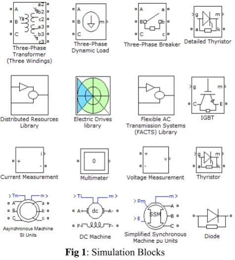
1.1 Matlab-Simulink for Power Electronics
Fig 1: Simulation Blocks
1.2 Performance parameters for Rectifiers
Before starting to examine various single-phase or multi-phase rectifiers’ circuits, we should define some parameters. These parameters are needed to compare the performances among the various structures. For the performance comparison we will assume ideal switches (diodes or thyristors) with zero commutation time (instantaneous turn on and off) and zero on-resistance (when conducting they present neither voltage drop nor losses).The DC voltage on the load is the average output voltage over the period T. [5]
0
1
(t).d(t)
T DC LV
V
T
=
(1)Similarly, it is possible to define the R.M.S. voltage on the load is given by:
2 0
1
(t).d(t)
T L LV
v
T
=
(2)The ratio of the two voltages is the Form Factor (FF). dc L
V
FF
V
=
(3)This parameter is very important because it is an index of the efficiency of the rectification process. If the load to be purely resistive, the currents can be define as
(t)
L(t)
L Lv
i
R
=
(4)
.
.
.
DC DC L L D LV
I
V I
R I
η
=
+
(5)L L L
V
I
R
=
(6)The rectification ratio (
η
), also known as rectification efficiency, is expressed by DC L DP
P
P
η
=
+
(7)
P
DC=
V
DC.
I
DC (8)
P
L=
V I
L.
L (9)
P
D=
R I
D.
2L (10)Where, PD=the losses in the rectifier RD=the equivalent resistance of the rectifier By developing Equation (7), using Equations (5), (8), (9) and (10), we get: 2 DC 2
.I
1
.
.
.
1 (
)
DC DC D L L D L L L
V
V
R
V I
R I
V
R
η
=
=
+
+
(11)The ripple factor is an important parameter for the rectifier which used to describe the quality of the rectification. The RF is defined as the ratio of the effective AC component of the load voltage versus the DC voltage. 2 2 2
1
L DC DCV
V
RF
FF
V
−
=
=
−
(12)One of the parameters used to define the characteristics of the transformer is the Transformer Utilization Factor (TUF). . . ( ) 2 DC P S P TUF V A V A = + (13)
Where,
VAP and VAS are the power ratings at the primary and secondary of the transformer
For the comparison of the different topologies, it is also useful to take into consideration the Peak Inverse Voltage(PIV) during the blocking state of the device or the
maximum current in the load. [10][11]
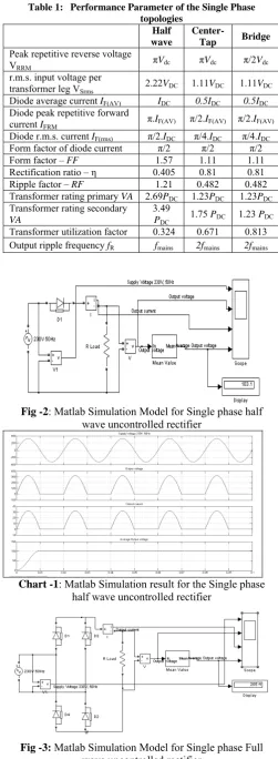
Table 1: Performance Parameter of the Single Phase topologies
Half wave
Center-Tap Bridge
Peak repetitive reverse voltage
VRRM πVdc πVdc π/2Vdc
r.m.s. input voltage per
transformer leg VSrms 2.22VDC 1.11VDC 1.11VDC
Diode average current IF(AV) IDC 0.5IDC 0.5IDC
Diode peak repetitive forward
current IFRM π.IF(AV) π/2.IF(AV) π/2.IF(AV)
Diode r.m.s. current IF(rms) π/2.IDC π/4.IDC π/4.IDC
Form factor of diode current π/2 π/2 π/2 Form factor – FF 1.57 1.11 1.11
Rectification ratio – η 0.405 0.81 0.81 Ripple factor – RF 1.21 0.482 0.482 Transformer rating primary VA 2.69PDC 1.23PDC 1.23PDC
Transformer rating secondary
VA
3.49
PDC 1.75 PDC 1.23 PDC
Transformer utilization factor 0.324 0.671 0.813 Output ripple frequency fR fmains 2fmains 2fmains
Fig -2: Matlab Simulation Model for Single phase half
wave uncontrolled rectifier
Chart -1: Matlab Simulation result for the Single phase
half wave uncontrolled rectifier
Fig -3: Matlab Simulation Model for Single phase Full
wave uncontrolled rectifier
Chart -2: Matlab Simulation result for the Single phase
Full wave uncontrolled rectifier
Fig -4: Matlab Simulation Model for 3-ØHalf wave
uncontrolled rectifier
As shown in figure 2, figure 3 and figure 4 represent the Matlab simulation model for the single and 3-Ø Uncontrolled rectifier. Same as Chart 1, Chart 2 and Chart 3 represent output simulation result for the same.
Chart -3: Matlab Simulation result for the 3-ØFull wave
3. SINGLE AND 3-ØPHASE CONTROLLED RECTIFIER As per the above simulation we have seen that it is necessary to vary the output voltage of the rectifier. The structures as given in Figure 2, 3 and 4 provide output voltages that are in a fixed ratio with the input AC voltages. The diodes alone cannot satisfy controlling requirements. The diodes are substituted with thyristors. The thyristor is a device whose transition from the blocking to the conducting state depends not only on the polarity of the anode–cathode voltage but is also controlled via the application of an adequate current pulse. Thyristors have three terminals: the trigger pulse is applied to the gate while the anode–cathode voltage is positive. The name thyristor derives from the Greek word thy-, meaning ‘switch’, and
the suffix -istor, which derives from transistor (trans-fer
res-istor) to indicate that the device belongs to the
semiconductor family [6][9]. Sometimes it is called Silicon Controlled Rectifier (SCR) to distinguish it from similar devices like the Gate Turn-Off thyristor (GTO) or the TRIode to control AC (Triac) or others, much less capable of handling high power, that are often used in the circuitry generating the trigger pulses for the SCR. In the rest of this paper, thyristor means SCR. In this section we still assume that we have ideal switches and purely resistive loads. Here pages we shall only consider three-phase systems and those topologies that are more commonly used to supply the load with variable voltage and, consequently, variable current. [7][8]
As shown in figure 5, figure 6 and figure 7 represent the Matlab simulation model for the single and 3-Ø controlled rectifier, where Chart 4, Chart 5 and Chart 6 represent output simulation result for the same.
Fig-5: Matlab Simulation result for Single phase half wave
phase controlled rectifier.
Chart -4: Matlab Simulation result for the Single phase
half wave controlled rectifier
Fig-6: Matlab Simulation result for Single phase Full wave
phase controlled rectifier.
Chart -5: Matlab Simulation result for the Single phase
Full wave controlled rectifier
Continuous
powergui
v + -V3
v + -V2
v + -V1
v + -V
Scope R Load In Mean
Mean Value i
+ -I
Display D6
D5
D4 D3
D2 D1
230V 50Hz2 230V 50Hz1 230V 50Hz
Output v oltage Output current Supply Voltage 230V, 50Hz
Av erage Output v oltage
Fig-7: Matlab Simulation result for 3-ØFull wave phase
controlled rectifier.
Chart -6: Matlab Simulation result for the 3-ØFull wave
CONCLUSIONS
As Power Electronics is one of the important branches in recent industry revolution and power electronic systems are getting more complex today, the simulation is one of the easiest and effective sources for research and design development. The use of this Simulation toolbox must be a part of the modern syllabus for the students to enhance their knowledge. Even with the help of present model students can simulate the power electronics circuit with various load & conditions to understand and to explore in the design field. Most studies either deal with devices like diodes or thyristors — simultaneously handling high currents and high voltages (up to some kA/kV, see for example, Refs. [12], [13], [14]) or with their control, for example the use of microcontrollers in a new design for firing pulse generation (see Ref. [15])
REFERENCES
[1] A. Hemant Mehar, “MATLAB Simulation Techniques in Power Electronics”, IEEE Technology and Engineering Education (ITEE),VOL. 7, NO.4 December, 2012.
[2] Singh-Khanchandani, “Power Electronics (Book)”, ISBN: 9780070583894, Publication Year: 2006.
[3] Lander, Cyril W. (1993). "2. Rectifying Circuits". Power
electronics(3rd ed. ed.). London: McGraw
Hill. ISBN: 9780077077143. [4] The MathWorks, Inc
[5] R. Visintini , “Elettra Synchrotron Light Laboratory, Trieste, Italy”.
[6] R.S. Ramshaw, Power Electronics Semiconductor Switches
(Chapman & Hall, London, 1993).
[7] P.C. Sen, Power Electronics (Tata McGraw-Hill, 1988).
[8] J. Schaefer, Rectifier Circuits: Theory and Design (Wiley, 1965).
[9] G.J. Wakileh, Power Systems Harmonics (Springer, 2001).
[10] M.H. Rashid (ed.), Power Electronics Handbook (Academic Press, 2001)
[11] A.W. Kelley and W.F. Yadusky, Phase-controlled rectifier line-current harmonics and power factor as a function of firing angle and output filter inductance, Proc. APEC’90.
[12] Eupec, Rectifier diode D 2601N, BIP AC / SM PB, 2002-05-31, Eupec Data Sheet.
[13] Eupec, Phase control thyristor T 2871N, BIP AM / SM PB, 2002-04-07, Eupec Data Sheet.
[14] Powerex Inc., FT1500AU-240 Ultra high voltage thyristor, Powerex Data Sheet.