Secure Communication between Two
Computers Using MATLAB with Des
Algorithm and Arduino Board
Astha Srivastava1, Er. Nitin Agarwal2
PG Student, Dept. of ECE, Raja Balwant Engg. Technical Campus, Agra, India 1 Assistant Professor, Dept. of ECE, Raja Balwant Engg. Technical Campus, Agra, India2
ABSTRACT:We are living in the information age. We need to keep information about every aspect of life and that information need to be secured from attacks. To be secured information needs to be hidden from unauthorized access (confidentiality), protected from unauthorized change (integrity), and available to an authorized entity when it is needed (availability). Information is now distributed but these three requirements have not changed. Large amount of data has been vitiated in the coming years therefore data security has become the most important aspect of information sharing. More private data is stored in the cloud. Practically, the quantity of data to be transferred is not the concern. The important factor is the channel, through which the data is transferred, should be secured. Cryptography is one such technique which is can ensure for secure transmission of the data. And, using cryptographic techniques security can be provided to the information. Cryptography’s main advantage is that the information is somehow distorted, scrambled by the sender, an encryption key is known only by the intended receiver who decrypts the message. This research work classifies the security between two devices in communication using Data Encryption Standard (DES) Algorithm with arduino. Arduino simplifies the communication between hardware and software development in order to get a system running interactively. It is a safe communication technique. DES Algorithm’s main advantage is that other users will not know what type of communication is held between the 2 user and it is hard to crack .Communication in MATLAB withArduinoHardware, we use this to communicate effectively with an Arduino board. This enables to perform tasks such as: Acquire analog and digital sensor data from Arduino board and Communicate with an Arduino board over a USB cable or wirelessly in Wi-Fi. Build customs to interface with additional hardware and softwares.MATLAB is a high level language. In this we can see results from I/O instructions immediately, without compiling. MATLAB allows matrix manipulation, Implementation of algorithm, thousands of built-in math, engineering, Plotting of function and data that use to quickly analyse and visualize data collected from Arduino, or any hardware.
KEYWORDS: Secure Communication, Encryption Algorithm, Des, Communication Through Matlab, Communication Through Arduino Hardware, Matlab, Arduino.
I. INTRODUCTION
Fig 1: Taxonomy of attacks with relation to security goal
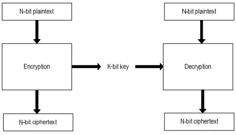
Fig 2: Encryption-decryption between two devices
Fig 1 shows a modern block cipher encrypts an n-bit block of plaintext or decrypts an n-block of cipher text. The decryption algorithm is the inverse of encryption algorithm and both operations are use with the same secret key so that receiver retrieves the message sent by sender. The encryption or decryption algorithm uses a k-bit key in order to get secure key-exchange channel.
A. Plain Text: The original text or message used in communication in called as Plain text For example Hello world is an example of a simple plain text.
B. Cipher Text: Any un-readable message that is obtained from a plain text is a cipher text.
C. Encryption: Encryption is used to convert Plain text into cipher text. This un-readable message can be communicated over any communication channel without the fear of the loss of confidentiality and integrity. Encryption process is done using encryption algorithm with the help of a key.
D. Decryption: Decryption process is just the opposite of encryption process, i.e. cipher text is converted into plain text using a particular decryption algorithm.
II. LITERATURE SURVEY
Various encryption algorithms were developed in the past decades. Some algorithms worked very efficiently, but they still have some overheads. There have been phenomenal refinements in the field of cryptography, since the internet security concept has come into existence, the old algorithms have still their importance in various applications so before discussing the research work, it is important to have a glance on the old popular symmetric key algorithms.Horst Feistel developed Data Encryption Standard, a symmetric key algorithm to encrypt block of data which is based upon Balanced Feistel network which uses 16 different iterations on the data and was designed to operate on different modes. The key size of DES is 56 bits only, which can be broken by using bruit-force techniques.
To enhance the performance of DES, Triple DES was introduced in 1998 which has a key size of 64 bits. Triple DES encrypts the data by using three different keys. Each block of data is encrypted by different three 56bit keys. The sender and receiver have to follow complex procedures to accomplish the encryption and decryption process in 3 levels and the large key size increases the complexity of algorithm. Besides the keys are of fixed size and do not change with time.
Rijmen V, Daemen J (1998) developed The Advanced Encryption Standard (AES). In AES block size of 128 bits is fixed, and key lengths are varied which can be of 128-bits, 192-bits or 256-bits. a symmetric key cryptography algorithm have been proposed by Kim et al. (2005) for a video file. Authors have developed a protection theme for MPEG-4 video file format. During this protection theme, with any symmetric key cryptography algorithm can encrypt the minimum segments of each Video Object Plane in an every MPEG-4 video file.
Debnath Bhattacharya et al. (2009) have proposed an approach to steganography to ensure data security. In this algorithm they combined cryptography, steganography and an extra security layer to encrypt text messages. The algorithm has used two keys one public and one primary to encrypt data. This layer concept increases computation time thrice to encrypt or decrypt the text message. Moreover the algorithm has worked only for text messages.
A new technique using block based transformation was proposed by Aditee Gautam (2011), used for image encryption. In this algorithm image is transformed into other image before encryption process is done. This transformation is done by Blowfish algorithm. Blowfish has a 64-bit block size and a variable key length from 32 bits up to 448 bits. It is based on 16 rounds. There are number of key dependent permutations and variable keys which are used on data at each round with XOR or addition operations. Blowfish is fast block algorithm, because the same key is used. But computation time increases when changing keys are applied. Each new key requires pre-processing equivalent to encrypt text, which is very slow compared to other algorithms. Secondly, if there is lack of synchronization between two parties then it will not be able to use the same key of encryption and decryption.
For all the other above mentioned algorithms, there are two common problems. First is the major computation is required for different iterations. Second is the unique key size. The key is fixed and it doesn’t change with the respective session. So, using a single key for long time doesn’t empower the message secrecy. Besides this, these techniques encrypt the message to a satisfactory level, therefore the cipher text can be cracked by using some complex permutation algorithm. To increase the level of security, Multi-Layer Data Security algorithms combining Cryptography and steganography are used, but it also tends to increase the response time and increasing the time or space complexity, which is not acceptable for large volumes of data
III. SCOPE OF RESEARCH
Standard, to improve the Bit Error Rate (BER) rate caused due to avalanche effect and is made more secure so that it can be used in wireless communication.
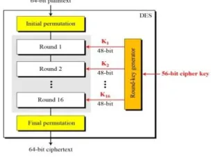
A. DES ALGORITHM: Our project is based on the Data Encryption Standard (DES) algorithm that is aSymmetric - key block cipher. DES is an implementation of a Feistel Cipher.It uses 16 round Feistel structure. The block size is 64-bit. Key length is 64-bit andDES has an Effective key length of 56 bits, since 8 of the 64 bits key are not used bythe Encryption algorithm (function as check bits only).
Fig 3: General structure of DES
INNER WORKING OF DES: Fig shows the element of DES cipher at the encryption site. Initial permutation takes 64-bit input and permutes them according to a predefined rule. The permutation is the inverse of the initial permutation. These two permutation cancel the effect of each other. In other words, if the rounds are eliminated from the structure, the cipher text same as the plaintext.Rounds: DES uses 16 rounds. Each rounds of DES is an invertible transformation, as shown in fig 3.2. The round takes and from the previous round (or the initial permutation box). Each round can have up to two cipher elements (mixer and swapper). Each of these elements is invertible because of the Xor operation. All noninvertible elements are collected inside the function ( , ).
Fig 4: DES each rounds
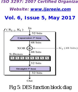
DES Function: The heart of DES is DES function. The DES function applies a 48-bit key to the rightmost 32 bits ( ) to produce a 32-bit output. This function is
Fig 5: DES function block diag
IV. PROPOSED METHODOLOGY AND DISCUSSION: HARDWARE
A. ARDUINO UNO BOARD
Introduction: Arduino is an open source microcontroller which can be easily erased, programmed and reprogrammed at any instant of time. It is introduced in 2005. The Arduino platform was found an inexpensive and easy way for students and professionals to create devices that interact with their surroundings using sensors and actuators. It is an open source computing platform that is used for constructing and programming electronic devices. It is based on simple microcontroller boards and also capable of acting as a mini computer just like other microcontrollers by taking inputs and controlling the outputs for various electronics devices.
It is also susceptible to receive and send information over the internet with the help of various Arduino shields. Arduino uses a hardware known as the Arduino development board and software for developing the code known as the Arduino IDE (Integrated Development Environment).Arduino is Built up with the 8-bit Atmel AVR microcontroller's that are manufactured by Atmel or a 32-bit Atmel ARM, these microcontrollers can be programmed easily using the C, C++ or MATLAB language in the Arduino IDE.
The development of Arduino board now also be used to burn a new code to the board by simply using a USB cable to upload.
Elements Of Arduino Boards :Project based on Arduino Board can be done into two categories:
Hardware
Software
Hardware: The Arduino Development Board comprises many components that together make it work effectively. Here are some main component blocks that help in its functioning:
Microcontroller: This is the most important part of the development board, which works as a mini computer and can receive as well as send information or command to the peripheral devices which are connected to it. The microcontroller uses are different from board to board. It also has its own various specifications.
External Power Supply: It is used to power the Arduino board with a regulated voltage ranging from 9 – 12 volts.
USB plug: This is a very important port in this board because it is used to burn a program to the microcontroller using a USB cable. It also has a regulated power of 5V which powers the Arduino board in cases when the External Power Supply is absent.
Internal Programmer: The developed software code can be uploaded to the microcontroller via USB port, without an external programmer.
Analog Pins: There are some analog input pins ranging from A0 – A7 (typical). These pins are used for the analog input / output. The no. of these pins also varies from board to board.
Digital I/O Pins: There are some digital input pins also ranging from 2 to 16 (typical). These pins are used for the digital input / output. The no. of these digital pins also varies from board to board.
Power and GND Pins: There are pins on the development board that provide 3.3, 5 volts and ground through them
Fig 6:Pin description of an Arduino board
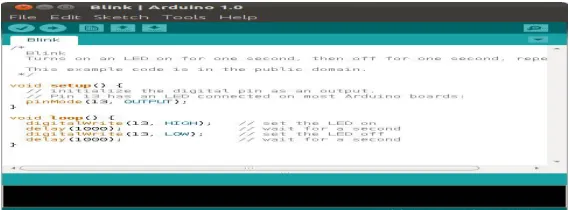
Software: The program code written for Arduino is commonly known as a sketch. For developing such sketches for an Arduino, software is used commonly known as the Arduino IDE. This IDE contains the following parts in it:
Text editor: In this the simplified code can be written using a simplified programming language.
Message area: It displays error and also gives a feedback on saving and exporting the code.
Text: The console displays text output by the Arduino environment including complete error messages and other information
Console Toolbar: This toolbar contains various buttons like Verify, Upload, New, Open, Save and Serial Monitor. On the bottom right hand corner of the window there displays the Development Board and the Serial Port in use.
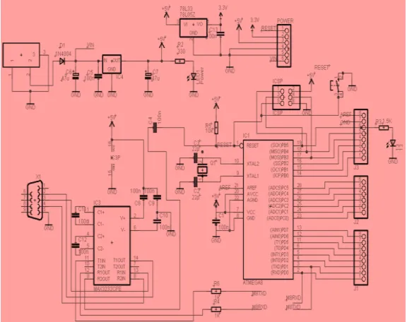
Fig 8: Arduino reference circuit
Arduino UNO consists of following component:
ATMEGA 328: The Atmega328 is a popular microcontroller chip produced by Atmel. It is a main is of Arduino board
or we can say it is the brain of Arduino. It is an 8-bit microcontroller and has 32K of flash memory, 1K of EEPROM, and 2K of internal SRAM. Atmega328 is one of the microcontroller chips that are used with the popular Arduino boards. The Arduino board comes with any 1 or 2 microcontroller chips, the Atmega168 or the Atmega328. From these 2, the Atmega328 is the upgraded or advanced chip. Unlike the Atmega168 which has 16K of flash program memory and 512 bytes of internal SRAM, the Atmega328 has 32K of flash program memory and 2K of Internal SRAM. The Atmega328 has 28 pins. It has 14 digital I/O pins, of which 6 is used as PWM outputs and 6 analog input pins. 2 of the pins are crystal oscillator. This is used to provide a clock pulse for the Atmega chip. There is a need of clock pulse for synchronization so that communication can occur between the Atmega chip and a device effectively that it is connected to.The chip is needed power so 2 of the pins, Vcc and GND that provide it power so that it can operate. The Atmega328 is a low-power chip, so it is only needed between 1.8-5.5V of power to operate.
Fig 9: ATMEGA 328 pin description
Power LED Indicator: It is to the right of the word “UNO” on the Arduino circuit board, there’s a tiny LED next to
the word ‘ON’. This LED is light up whenever you plug your Arduino into a power source. If this light doesn’t turn on it means there’s a chance that something is wrong.
pins 0 and 1, and a second time next to the TX and RX indicator LEDs. These LEDs will give us some nice visual indications when our Arduino is receiving or transmitting data.
Voltage Regulator: It is not only something you can interact with on the Arduino but also it is useful. The voltage regulator does exactly what its name says – it controls the amount of voltage i.e. let into the Arduino board. It is kind of gatekeeper that will turn away an extra voltage that might harm the circuit. Yes, it has its limits-not greater than 20v.
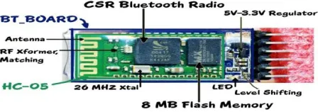
B. .HC-05 BLUETOTH MODULE: Bluetooth is a type of wireless communication that is used to transmit voice and data at high speed using radio waves. It is used for short range radio communications between many different types of devices, including mobile phones, computers and other electronics devices. Bluetooth range is around 10 meters and data transfer rate is 3 Mbps.
HC-05 is a more capable module that can be set as either Master or Slave.
HC-06 is a Slave only device. It is not use as Master It looks just like the HC-05.
HC-05 and HC-06 both small 3 cm long modules can run on 3.3V power with 3.3V signal levels.
Two types of modes of operation is used, first is Command Mode in which we can send AT commands to it and Data Mode where we can transmits and receives data from another Bluetooth module.
"Breakout" Boards make these easy to use. These mount the sub-module like that shown on the right on a slightly larger board. Mostly these boards support operation at 5V power and interface with 5V Arduino signal levels. A typical "breakout" board is shown in figure: 4.5.
Fig 10: HC-05 Bluetooth module
C. CONNECTING: HC-05 MODULE AND ARDUINO BOARD:In order to do this we need to follow below steps:
Step-1: HC-05 is a serial port module that’s why it is very easy to use.
Connect VCC with 3.3V of Arduino; do not connect it with 5V because that can cook the module.
Connect GND with any GND of Arduino
Connect Rx pin of Bluetooth with Tx of Arduino
Connect Tx pin of Bluetooth with Rx of Arduino
Then power-up the Uno using USB cable, a red light LED on HC-05 will start blinking that means connections are correct.
Step-2: Connect the LED and Control It Using Arduino Serial Monitor.
Step-4: Get HC-5 to Work With Arduino and Test the Communication.
Fig 11:Connection between HC-05 Bluetooth module-Arduino
V. PROPOSED METHODOLOGY AND DISCUUSION: SOFTWARE: MATLAB
MATLAB is a short form of MATrix LABorator. It is a programming package and makes quick and easy scientific calculations and I/O. It has hundreds of built-in functions for various computations and many toolboxes designed for specific research, including statistics, optimization, solution of partial differential equations and data analysis. For communication between two devices in matlab, you need a sound knowledge in basics of MATLAB commands and several advanced features.
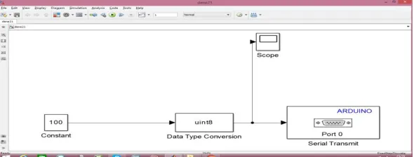
SIMULATION IN MATLAB :Simulation is the initiation of the operation of real world process. Simulation modeling is applied methodology which describes the behavior of a system, conduct theories or hypotheses that account for the observed behavior and then use these theories to predict future behavior.fig 5.5 shows simulink window.
Arduino Serial Transmission Model In Simulink Matlab:In Simulink use the play button, and run another model on the Arduino using the "Tools->Run on Target Hardware->Run" option.I have included two models which perform this functionality. The transmitting model is called "SerialSend" and the receiving model is called "ArduinoReceive". The SerialSend model should be run by using the play button while the ArduinoReceive model should be run by selecting "Tools->Run on Target Hardware->Run" to push code to the Arduino. The transmitting model sends a pulse with values of 2 and 3. The pulse has a period of 4 seconds with a 50% duty cycle. In the receiving model just checks to see if the value sent is a 2 or 3 and sends a corresponding Boolean to pin 13. On the Arduino Mega 2560 and Uno this will cause the corresponding onboard LED to blink with a period of 4 seconds.
VI. EXPERIMENTAL RESULTS WITH FIGURE AND CODING IN MATLAB
ARDUINO-HC05: MASTER SLAVE SET UP:In the setup- at the master, we set the LED pin as output and set it low right away, and then start the serial communication at 9600 baud rate. Similar, at the slave, we set the button pin as input and define the servo to which pin is connected and start the serial communication with the same baud rate.In the loop section, in both code, with the Serial.available() function we check whether there is available data in the serial port to be read and using the Serial.read() function we will read and store the data into the “state” variable. So if the master receive the character ‘1’ which is sent from the slave when the button state is high, or the button is pressed, the LED will be on. Else if the character is ‘0’ the LED will be off.
Fig 13:ARDUINO-HC05: Master-slave: Hardware set up
HOW TO CONNECT ARDUINO BOARD WITH MATLAB:Now we are going to create simple MATLAB m-files to talk to our Arduino board. lets you use MATLAB to communicate with your board through USB cable.
Step 1: Select Arduino from a list of support packages then click Next to see a list of support packages and select Arduino from the list for MATLAB Support Package and Arduino Due for the Simulink Support Package.
Fig 14:Selection of Arduino package in MATLAB
Step 2: Then click next and log in to Math work account then continue and complete the installation.
Step 3: To establish a connection between MATLAB and Arduino boards, the following command can be used from MATLAB.
This command connects MATLAB to the first Arduino detected on the system. A MATLAB variable by the name 'a' should now appear on the workspace or an error message indicating what went wrong.
Fig 13:MATLAB-ARDUINO Connection preparation
To switch on the LED connected to Pin 9 on the Due, execute the following command
Then we are sending a request from MATLAB to Arduino, to write on the Digital Pin 9 the value of 1. This will switch ON your LED. To blink the LED, we have to switch it ON and OFF periodically.
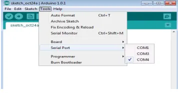
Step4 : Now we mention the COM port at which the Due is connected to the computer.
Fig 14:Tool-COM4 is selected for MATLAB-ARDUINO Connection
Step 5: Now we can ready to serial communication between MATLAB and Arduino.
CONCLUSION: The thesis presents a introduction and analysis of all encryption algorithm like DES, AES, RSA and discussed about the types of cryptography. And complete analysis of DES algorithm. Then define the ARDUINO board and HC-05 Bluetooth module and make the connection between them to create master-slave circuit. In this we also talk about MATLAB and discussed the basic operation. Then finally connect the hardware to software. Establish the >> writeDigitalPin(a, 9, 1)
for i = 1:10
writeDigitalPin(a, 9, 1);
pause(0.5);
writeDigitalPin(a, 9, 0);
pause(0.5);
end
connection between MATLAB and Arduino-HC05 Bluetooth module then communicate between two devices using MATLAB through master and slave connection via USB cable.
REFERENCES
1. T. Bala and Y. Kumar, “Asymmetric Algorithms and Symmetric Algorithms: A Review,” International Journal of Computer Applications (ICAET), pp.1-4, 2015.
2. W. Stallings, Cryptography and Network Security, 4th Ed, pp. 58-309, Prentice Hall, 2005.
3. Guiliang Zhu, Weiping Wang and Xiaoqiang Zhang, ZGW-1 digital image encryption algorithm based on three levels and multilayer scramble: A Review, “IEEE’
4. R. Schilling and S. Harris. Fundamentals of Digital Signal Processing using MATLAB. Canada: Thompson Publishing Co. 2005.
5. Prof. G. Lockwood, Measurement Instrumentation and Experiment Design General Instrumentation Experiment No. 1, Serial Port Communication using MATLAB
6. Adel A. El-Zoghabi, Amr H. Yassin, Hany H. Hamdy, Public key cryptography based on chaotic neural network, Published in International Journal of Computer Application.
7. Soheila Omer AL Faroog Mohammed Koko, Dr.Amin Babiker A/Nabi Mustafa, Comparison of Various Encryption Algorithms and Techniques for improving secured data Communication, A Review: IOSR Journal of Computer Engineering (IOSR-JCE).
8. Mrs. Anisha Cotta, Miss. Naik Trupti Devidas, Miss. Varda Kalidas Naik Ekoskar, wireless communication using hc-05 bluetooth module interfaced with arduino, International Journal of Science, Engineering and Technology Research (IJSETR).
9. Leo Louis, working principle of arduino and using it as a tool for study and research, International Journal of Control, Automation, Communication and Systems (IJCACS), Vol.1, No.2, April 2016.
10. Nirmaljeet Kaur, Sukhman Sodhi, Data Encryption Standard Algorithm (DES) for Secure Data Transmission, International Journal of Computer Applications (0975 – 8887) International Conference on Advances in Emerging Technology (ICAET 2016).
11. Banzi, Massimo. Getting Started with Arduino. Sebastopol, CA: O‟Reilly, 2009.
12. Panth Shah, Tithi Vyas, Interfacing of MATLAB with Arduino for Object Detection Algorithm Implementation using Serial Communication , International Journal of Engineering Research & Technology (IJERT) ISSN: 2278-0181www.ijert.orgIJERTV3IS100766 Vol. 3 Issue 10, October- 2014.
13. http://arduino.cc/en/Tutorial/HomePage .