http://internationaljournalofresearch.org/ P a g e | 394
D-Q Control Based Statcom for Reactive Power
Compensation
GADUPALLI ROJARANI
M-tech student Scholar
Department of Electrical & Electronics Engineering, RAJAMAHENDRA COLLEGE OF ENGINEERING, IBRAHIMPATNAM;
RANGA REDDY (Dt); Telangana, India. Email:[email protected]
MR.A.SRINIVASULU
Assistant Professor
Department of Electrical & Electronics Engineering, RAJAMAHENDRA COLLEGE OF ENGINEERING, IBRAHIMPATNAM;
RANGA REDDY (Dt); Telangana, India. Email:[email protected]
Abstract: The STATCOM is a shunt connected FACTS device which supplies reactive power to the load to improve the voltage stability of the load busses. The STATCOM in multi bus system is capable of reducing the losses and improving the voltage regulation. This work deals with comparison of Push Pull and Voltage Inverter based STATCOM for multi bus system. Eight bus systems are modeled using the elements of SIMULINK. The models are developed for eight bus system with and without STATCOM. The two STATCOM systems are compared with respect to total harmonic distortion and reactive power comparison. The STATCOM is studied with respect to the voltage stability improvement at the load busses. The results of VSI based STATCOM system are compared with those of Push pull inverter based STATCOM system. The term power quality is used in synonymous with supply reliability to indicate the existence of an Adequate and secure power supply. Power quality is generally used to express the quality of the voltage. The Reactive power may be compensated in many ways including FACTS controller, fixed capacitors and synchronous condensers etc.The proposed concept can be implemented by using Fuzzy logic controller by using Mat lab/simulink software.
Keywords-microgrid; back-to-back; inter-link converter; voltage control mode; PQ control mode
I INTRODUCTION
Micro grids have been introduced as alternatives to conventional centralized grids. These systems will play an important role in the future of smart grids. A Microgrid can usually operate either in grid-connected or island mode. Electro-static switches are normally used to make an AC microgrid completely separated from the utility in an island mode of operation. Therefore, the critical loads can survive from the disturbances in frequency/voltage of the utility grid. In this condition, the utility grid has been lost as a stiff resource.
The static switches can be replaced with an ac-dc-ac converter. This back-to-back (b-to-b) converter as an interlink converter can offer the following benefits:
Isolating the microgrid from the utility while keeping the flow of power between them.
Removing the necessity of the
resynchronization, when the microgrid is intended to reconnect to the utility grid.
Facilitating power flow control between the microgrid and the utility.
In recent years, the idea of using ac-dc-ac converter as the interlink between microgrid and utility grid has been proposed, but its application limits to power flow control [1]. In this work, it is intended to extend this application to another voltage control mode of operation. The b-to-b converter also has been used to interlink two or more independent micro grids operating at different voltage and frequency [2].
In this paper, the microgrid is intended to work in two different modes with the b-to-b converter. In mode-I, the active and reactive power flow from the utility to the microgrid is controlled. In this mode, the grid has no contribution to the voltage control of the microgrid and the microgrid is seamed as a PQ load from the grid view. This mode will be called as PQ control mode. This operation of contributing to the active/reactive power can only be achieved by the use of a b-to-b converter. The other operation is when the b-to-b converter works in mode-2, in which the voltage of the microgrid is controlled with the interlink converter. In this mode, the idea is to maintain the utility current in-phase with its voltage without any unbalances or harmonics, in the presence of nonlinear and unbalanced loads in the microgrid. This is one of the most important benefits of the proposed interlink converter which will remove the necessity of using a DG active filter and a power factor correction device.
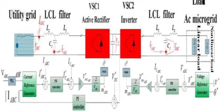
As shown in Fig.1, the b-to-b converter is used with an LCL filter on both sides to attenuate the converter switching ripples. In the stationary frame used in this paper, the proportional resonant (PR) controller must be used for tracking sinusoidal references. The PR controller is recently used for several purposes such as, reactive power control in island microgrid [8] and harmonic sharing in the microgrid [9]. In the next sections, the approaches used for designing the control loops in the voltage and the PQ control modes, are explained using the methods introduced in [3]. Several approaches have been used for parameter tuning of the multi -loop controllers in the literature, such as the iterative process [4] and pole-zero cancellation [5].
Fig.2. Back to back converter operated in the PQ control mode (mode-1) or voltage control mode (mode-2)
II POWER CIRCUIT STRUCTURE
A Schematic diagram of the system under study. It consists of an active rectifier with an LCL filter, a DC-link capacitor and an inverter with another LCL filter. The parameters of the LCL-filters are determined according to some factors such as current ripple, resonant frequency, the permissible reactive power injected by the filter capacitor, voltage attenuation caused by the filter and passive and active damping that must be added in series with the capacitor of the filter.
In this work, active damping is used and introduced as the inner loop of the controllers. The configuration and parameters of the filters of the rectifier and inverter used in the proposed inter-link converter are the same. These parameters have been designed according to the characteristics of the power circuit and the aforementioned factors. The electrical characteristics of the power circuit and parameter values are listed in Table 1.
TABLE .1: Electrical and Physical Characteristics of the System
III CONTROL SYSTEM STRUCTURE
The b-to-b converter can be used in two different modes depending on the structure of the microgrid. In Mode-1, the proposed inter-link converter is used in a condition in which the voltage of the AC microgrid is set by its own resources and the converter has no contribution to it. As shown in Fig.2, in this mode, the b-to-b converter is controlled to inject or absorb pre-specific amount of active and reactive power to or from the microgrid depending on the operator decisions. In another control mode, the b-to-b converter controls the voltage of the microgrid or contributes to it in conjunction with the resources in the microgrid.
As illustrated in Fig.2, the control loop of the utility side converter is unique in both modes of operation. In this converter, a current controller is used in which the magnitude and the phase of the current reference are determined respectively, to control the DC-link voltage and to not draw any reactive power from the utility. However the microgrid side converter uses different control loops. In Mode-1, a current controller is applied to inject the desired active and reactive power to the microgrid but in Mode-2, a voltage control loop is used to control the voltage of the microgrid system. The inner loop in both voltage and current control loops is used for active damping and fast dynamic response.
http://internationaljournalofresearch.org/ P a g e | 396
(1)
Where ωc is the resonant frequency.
The controller gain is now finite but still relatively high to have a small steady state error. The controller bandwidth is widened by setting larger values for We. This could help the controller work properly in spite of variations in the frequency. If the resonant integrator is accompanied by a proportional term, the result will be a proportional resonant ( PR) controller as expressed in (2).
(2)
Where Kp is the proportional gain.
As in the PI controller, the dynamic response of the system such as bandwidth, phase and gain margins is dominantly tuned by Kp and the steady
state behavior of the system can be tuned by choosing an appropriate value for Ki•
1 Voltage Control Loop
In voltage control mode the magnitude and frequency of the grid are controlled under load current variations. In this mode, the voltage of the capacitor of the filter is measured and compared with the reference voltage, and the output is given to the controller. In this scheme, an inner current loop is introduced not only for damping the LC-resonance introduced by the filter but also for improving the overall system stability. For this reason, the capacitor current of the output filter is fed back into the current control loop so as to provide both active damping and disturbance rejection enhancement.
The inner controller is a gain (Kc) that is
selected such that its effect on the outer loop is considered. The system is modeled in Fig.3.3. The load is modeled as two parts, a linear part and a non-linear part. The linear current load is modeled as a function of the output voltage, however the non-linear part is considered as a disturbance in the model.
Fig.3. Modeling of an inverter operated as a voltage controller
In the design process, the value of Kc is
set to a very low value for damping the resonant frequency. Larger values of Kc result in higher
gains at lower frequencies that could amplify low-frequency noises [3]. Additionally, larger values of Kc produce larger phase lag at the
operating frequency that could deteriorate both reference tracking and disturbance rejection.
Fig.4. Root locus of the open loop system in voltage control mode
Then, the value of Kp must be determined
considering the system dynamic performance. As depicted in Fig 5, the root locus of the system is optimized for the damping ratio of 0.7 with the controller parameters of Kc=4 and Kp= O.l. In
addition to the resonant controller at the operating frequency, harmonic resonant controllers must be added for the rejection of load harmonic currents as given in (3).
(3)
The integral term for each frequency is determined according to its desired magnitude. Assuming that We is equal to 1.5rad/s, the integral terms are tuned to have the desired bandwidth and provide maximum possible magnitude at the operating frequency and its harmonics. Here the bandwidth is set to 5500 rad/s. The bode diagram of the final open-loop system is illustrated in Fig.5.
2 PQ control Loop
Another operation mode of the inverter is the PQ control mode. In this mode the microgrid includes voltage sources as well. In this condition, the reference of the current is determined based on the desirable active and reactive powers and the load voltage. The inner current loop is the same as that in the voltage control mode, and the inverter must inject a particular amount of active and reactive powers which determines the magnitude and phase of the reference current. Fig.6 shows a block diagram of the inverter working in this mode of operation.
Fig.6. Modeling of an inverter operated as a PQ controller
Fig.7. Root locus of the open loop system in the PQ control mode
The design process of the outer and inner controller in this mode is the same as the process described for the voltage control loop, i.e. Kc=4.
To determine a proper value for K,,, the root locus of the system is plotted in Fig.7. As it can be seen from this figure, a suitable value for Kp to
have an optimum dynamic behavior is 0.26.
Now, the integral term and the cutoff frequency are specified according to the desired bandwidth and tracking at the operating frequency. In the PQ control mode, there is no need to add a harmonic resonant controller. Within the previous assumption for We, the value of the integral term is tuned at 100 to have a bandwidth equal to 2840radls, which is small enough as compared to the resonant frequency. To achieve this bandwidth the value of Kp must be
increased, such that the damping ratio will be decreased enough. For this reason, a phase lead compensator is added to increase the phase at the cross over frequency. The bode diagram of the final open loop system is illustrated in Fig.8.
Fig.8. Bode diagram of the open loop system with current controller
3 DC-link Voltage Control Loop
To maintain the voltage of the DC-link in a back to back converter at a constant value, the active power that flows into the DC-link must be equal to the active power absorbed by the load. For this purpose, the voltage of the capacitor must be measured and compared to the reference one. The error is given to a PI controller to produce the amplitude of the current reference of the grid-side converter. It is worth mentioning that this current reference must be in-phase with the utility grid voltage in order not to draw any reactive power from the utility. The model of the DC-bus voltage control loop is shown in fig.9. In this figure, T, is the time constant of the current control loop of the grid-side converter which is equal to:
http://internationaljournalofresearch.org/ P a g e | 398
(4)
Where Ro and K are the steady-state
equivalent resistance and the transfer function from the current amplitude to the active power, respectively, which can be found as:
(5)
(6) As shown in Fig.9, the system has a right-hand pole. Therefore the phase and gain margin criteria could not be used for stability of the closed loop system. Thus the design procedure must be done using the zero/pole placement in the Z-plane [7]. The PI controller is designed as:
(7) Where P=1.1 and 1=52.
The performance of the designed controller is investigated in the next section.
IVINTRODUCTIONTOFUZZYLOGIC CONTROLLER
L. A. Zadeh presented the first paper on fuzzy set theory in 1965. Since then, a new language was developed to describe the fuzzy properties of reality, which are very difficult and sometime even impossible to be described using conventional methods. Fuzzy set theory has been widely used in the control area with some application to dc-to-dc converter system. A simple fuzzy logic control is built up by a group of rules based on the human knowledge of system behavior. Matlab/Simulink simulation model is built to study the dynamic behavior of dc-to-dc converter and performance of proposed controllers. Furthermore, design of fuzzy logic controller can provide desirable both small signal and large signal dynamic performance at same time, which is not possible with linear control technique. Thus, fuzzy logic controller has been potential ability to improve the robustness of dc-to-dc converters. The basic scheme of a fuzzy logic controller is shown in Fig 5 and consists of four principal components such as: a fuzzification interface, which converts input data into suitable linguistic values; a knowledge base, which consists of a data base with the necessary linguistic definitions and the control rule set; a decision-making logic which, simulating a human decision process,
infer the fuzzy control action from the knowledge of the control rules and linguistic variable definitions; a de-fuzzification interface which yields non fuzzy control action from an inferred fuzzy control action [10].
Fig.10 General Structure of the fuzzy logic controller on closed-loop system
The fuzzy control systems are based on expert knowledge that converts the human linguistic concepts into an automatic control strategy without
any complicated mathematical model [10].
Simulation is performed in buck converter to verify the proposed fuzzy logic controllers.
Fig.11. Block diagram of the Fuzzy Logic Controller (FLC) for dc-dc converters
A. Fuzzy Logic Membership Functions:
The Membership Function plots of error
The Membership Function plots of change error
the Membership Function plots of duty ratio
B. Fuzzy Logic Rules:
The objective of this dissertation is to control the output voltage of the boost converter. The error and change of error of the output voltage will be the inputs of fuzzy logic controller. These 2 inputs are divided into five groups; NB: Negative Big, NS: Negative Small, ZO: Zero Area, PS: Positive small and PB: Positive Big and its parameter [10]. These fuzzy control rules for error and change of error can be referred in the table that is shown in Table I as per below:
V.MATLAB/SIMULINK RESULTS
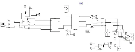
Fig 12 Matlab/simulation circuit of back to back converter operated in the PQ control mode or voltage control mode
Fig 13 Three phase voltage of the microgrid in the voltage control mode with adding six-pulse rectifier to load at O. 08
Fig 14 Three phase current of the microgrid(top figure) and utility grid(lower figure) in the voltage mode control with
add mg six-pulse rectifier to load at t=0. 08
Fig 15 DC-bus voltage in the voltage mode control with adding six pulse rectifier at t=O. 08.
Fig 16 Three phase voltage of the microgrid in the voltage control mode with adding single phase load at t=0. 08.
Fig 17 Three phase current of the microgrid (top figure) and utility grid (lower figure) in the voltage mode control with adding single
phase load at t=O. 08.
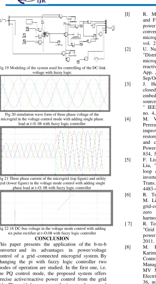
http://internationaljournalofresearch.org/ P a g e | 400 Fig 19Modeling of the system used for controlling of the DC-link
voltage with fuzzy logic
Fig 20 simulation wave form of three phase voltage of the microgrid in the voltage control mode with adding single phase
load at t=0. 08 with fuzzy logic controller
Fig 21 Three phase current of the microgrid (top figure) and utility grid (lower figure) in the voltage mode control with adding single
phase load at t=O. 08 with fuzzy logic controller
Fig 22 18DC-bus voltage in the voltage mode control with adding six pulse rectifier at t=O.08 with fuzzy logic controller
CONCLUSION
This paper presents the application of the b-to-b converter and its advantages in power/voltage control of a grid -connected microgrid system. By changing the pi with fuzzy logic controller two modes of operation are studied. In the first one, i.e. the PQ control mode, the proposed system offers precise active/reactive power control from the grid side. The grid has no contribution to the control of the microgrid voltage. In the second control mode, i.e. Voltage control with fuzzy logic controller mode although the grid has a role in the control of both the power flow and voltage of the microgrid, it is slightly affected by the disturbances in the microgrid system.
REFERENCES
[I] R. Majumder. A. Ghosh. G. Ledwich. and F. Zare. "Power management and power flow control with back-to-back converters in a utility connected microgrid," IEEE Trans. Power Systems. , vol. 25, no. 2, pp. 0885-8950, May. 2010. [2] U. Nutkani, P. C. Loh, and F. Blaabjerg, "Distributed operation of interlinked AC microgrids with dynamic active and reactive power tuning, " IEEE Trans. Ind. App. , vol. 49, no. 5, pp. 0093-9994, Sep/Oct. 2013.
[3] J. He, and Y. W. Li, "Generalized closed-loop control schemes with embedded virtual impedances for voltage source converters with LC or LCL filters, " IEEE Trans. Power. Electron. , vol. 2 7, no. 4, pp. 0885-8993, April. 2012. [4] M. Vilathgamuwa, A. A. D. Ranjith
Perera, and S. S. Choi, "Performance improvement of the dynamic voltage restorer with c1osed-loop load volt- age and current-mode control," IEEE Trans. Power Electron. , vol. 17 , no. 5, pp. 824-834, Sep. 2002.
[5] F. Liu, S. Duan, J. Yin, B. Liu, and F. Liu, "Parameter design of a two current-loop controller used in a grid-connected inverter system with LCL filter," IEEE Trans. Ind. Electron. , vol. 56, no. II, pp. 4483-4491, Nov. 2009.
[6] R. Teodorescu, F. Blaabjerg, U. Borup, M. Liserre, "A new control structure for grid-connected LCL PV inverters with zero steady-state error and selective harmonic compensation," IEEE 2004. [ 7] R. Teodorescu, M. Liserre, P. Rodriguez,
"Grid converters for photovoltaic and wind power systems," John Wiley & Sons, Ltd 2011.
[8] M. Hamzeh, H. Mokhtari, and H. Karimi, "A Decentralized Self-Adjusting Control Strategy for Reactive Power Management in an Islanded Multi-Bus MV Microgrid," Canadian Joumal of Electrical and Computer Engineering, vol. 36, no. I , pp. 18-25, Winter 2013.
[9] M. Hamzeh, H. Karimi, and H.
Mokhtari, "Harmonic and