A Compensator Based Control for
Non-Interacting Tank System
S.Gomathy1, L. Jenifer Amla2, J. Glory Priyadharshini3
Assistant Professor, Dept. of EEE, Sri Ramakrishna Institute of Technology, Coimbatore, Tamilnadu, India1
Assistant Professor, Dept. of EEE, Sri Ramakrishna Institute of Technology, Coimbatore, Tamilnadu, India2
Assistant Professor, Dept. of EEE, Sri Ramakrishna Institute of Technology, Coimbatore, Tamilnadu, India3
ABSTRACT:Proportional-Integral-Derivative (PID) controllers are commonly employed in process control applications to obtain the desired response. They are found to yield optimum results in such applications. An attempt has been made in this article to employ a Non-Iterative compensator as an alternative to conventional controller and intelligent controller for a two tank Non-Interacting system. Experimental results are obtained by observing the transient response of liquid level using the compensator as well as Conventional and Intelligent controller. The compensator based control is found to yield better results than a PID controller, Internal Model Control (IMC) based PID controller and Fuzzy tuning PID. Since the implementation of the Non-Iterative compensator involves only three passive components, it can be extended appropriately even for interacting tanks system and many such processes.
KEYWORDS:Non-Interacting Tank system, Ziegler Nichols tuned PID controller, IMC based PID controller, Fuzzy tuning PID and Non-Iterative Compensator.
I.INTRODUCTION
The control of liquid level in Non-Interacting tank system is a major problem in process industries like chemical industries, paper & pulp industries, pharmaceutical industries and power plants. The liquid in the tank will be processed by chemical or mixing treatment, but often the level of liquid in the tank must be controlled and maintained [1]. Based on the accuracy of the levels, the quality of the final product is determined [2]. The main objective of this work is to maintain and control the level of Non-Interacting tank at desired setpoint.
In proposed work, level of a non-interacting tank is controlled by conventional PID tuning techniques, PID tuning using intelligent controller technique and Non-Iterative compensator technique. Result obtained from these techniques are compared and analyzed for the better improvement of the system to obtain its desired setpoint with less time consumption.
Generally PID controller is mainly used in all process industries to control the certain process. Because of their performance, it is said to be work-horse of process industries [3]. Different tuning methods are implemented to find the effective controller parameters, in order to obtain better results [4]. In this work PID parameters are tuned using Ziegler-Nichols (Z-N), IMC based PID and Fuzzy tuning PID. Even though tuning of PID parameters obtains better results there are some difficulties to tune the PID parameters [5]. To overcome the problems of tuning methods a simple Non-Iterative Compensator technique is proposed in this work to control the level of Non-Interacting tank.
II.MATHEMATICAL MODELING
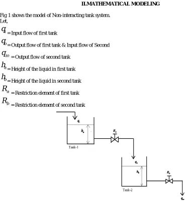
Fig 1 shows the model of Non-interacting tank system. Let,
i
q
= Input flow of first tank
o
q
= Output flow of first tank & Input flow of Second
io
q
= Output flow of second tank
a
h
= Height of the liquid in first tank
b
h
= Height of the liquid in second tank
a
R
= Restriction element of first tank
b
R
= Restriction element of second tank
Fig. 1 General model of Non-Interacting tank System
Any changes in levelℎ of Tank-1 will change the level ℎ of Tank-2, but the converse is not possible. This type of system is said to be Non-Interacting tank system [8].
According to the Law of conservation of Mass, Tank-1:
dt dh C q
q 1
1 2
1
(1)
1
q
= Input Condensate flow to the first tank2
q
= Output flow from the first tank & Input flow to the second tank1
1
h
= Height of the Tank-1Since the Resistance of the tank-1 is small,
2
q
gets negligible, So equation (1) becomes,dt dh C q 1 1 1 (2) Tank-2: dt dh C q q 2 2 3
2
(3)
2
q
- Input Flow to the second Tank3
q
- Output flow from the second tank2
C
- Accumulation of tank-22
h
- Height of the second tankConsider the flow rate of
q
1 as the flow rate ofq
2, since the valve coefficient ofq
2is negligible.Valve coefficient for
q
3is,2 2 3
R
h
q
(4) Therefore, the overall Transfer function of the system is,S C S C C R R S Q S H 1 2 2 1 2 2 1 2 ) ( ) ( (5) By experimental method, the values for the above Transfer function are calculated. Therefore the Non- Interacting Tank model is,
S S S Q S H 2 1 2 2 1 . 0 ) ( ) ( (6)
III.ZIEGLER- NICHOLS TUNING METHOD
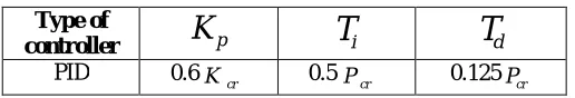
PID parameters are obtained from the Ziegler–Nichols tuning formula shown in Table I. By adjusting the gain of the system, critical gain (Kcr ) can be measured and oscillation period also measured in terms of critical period (Pcr) .The PID values are tuned from oscillatory response parameters [9]. Increase Kpfrom 0 to critical value Kcr at which the
Table I Z-N method for PID tuning
Type of
controller
K
pT
iT
dPID 0.6K cr 0.5Pcr 0.125Pcr
PID parameters are determined by substituting the values of Kcr (critical gain) = 6.7 and Pcr (critical period) = 27 seconds in the Table I.
ThereforeKp 4,Ki 1,Kd 0.1
The response of Non-Interacting tank using Z-N tuned PID controller is shown in fig 3 and the time domain specification for the response is shown in Table II. Since trial and error procedure must be performed to get the oscillatory response it is said to be a time consuming method [11]. To overcome the above said drawback, IMC based PID controller is proposed.
Table II Time domain Specifications for Non-Interacting tank using Z-N PID tuning
Type of controller
Settling Time
Peak Overshoot
Rise Time
PID 120 Seconds 67% 3.678 Seconds
IV.IMC BASED PID
PID parameters are found by IMC based PID tuning formula shown in Table III. IMC design procedure could be used to develop an equivalent PID-type control law. For stable process with no time delay, the IMC based PID procedure gives exactly the same feedback performance as IMC [12] [13].
Table III Controller parameters for IMC based PID method
Types of controller
p
K Ti Td
PID
c
K )
( 1 2 1 2
2 1
2 1
Where,
2 1
&
= Time Constantc
K = Gain
= optimum filter tuning factor (Assumable)By substituting the values of
1= 1 sec,
2= 2 sec,K
c = 0.1 and
= 1 in the table 3, PID parameters are determined. Therefore,K
p
8
,K
i
2
.
83
,K
d
3
Table IV Time domain Specifications for Non-Interacting tank using IMC based PID
Type of controller
Settling Time
Peak Overshoot
Rise Time
IMC based PID 109 Seconds 63% 2.68 Seconds
V.FUZZY TUNED PID
In contrast to conventional control techniques, fuzzy logic control (FLC) is best utilized in complex processes that can be controlled by a skilled human operator without much knowledge of their underlying dynamics. The basic idea behind FLC is to incorporate the "expert experience" of a human operator in the design of the controller in controlling a process whose input – output relationship is described by collection of fuzzy control rules (e.g., IF-THEN rules)
involving linguistic variables rather than a complicated dynamic model[14][15].E and dt
de (Error and derivative error)
are the inputs for Fuzzy logic controller. Hence Fuzzy Controller is used to develop the fuzzy rules for rewriting the PID parameters to meet desired specifications. Where, R (T) is the desired input and Y (T) is the output. Fig 2 shows the general block diagram of fuzzy tuning PID for controlling the level of Non-Interacting tank.
Fig. 2 General Block Diagram of Fuzzy Tuning PID
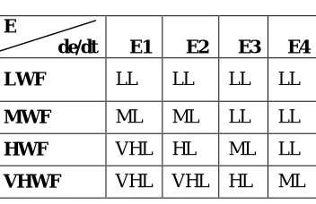
Based on the inputs i.e., error and change in error, the output response for level is obtained. The triangular shape membership functions are chosen for both the inputs. The membership functions of input and output control signals. By using the input and output membership functions, the fuzzy IF-THEN rules are framed for Non-Interacting system. Table V shows the fuzzy rules for controlling the level of Non-Interacting tank based on the error and change in error of the level.
Table V Fuzzy Rules for level control
E
de/dt E1 E2 E3 E4
LWF LL LL LL LL
MWF ML ML LL LL
HWF VHL HL ML LL
VHWF VHL VHL HL ML
which makes them complicated [16]. The drawback present in the intelligent controller is overcome by the simple Non-Iterative compensator technique in the proposed work.
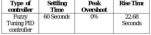
Table VI Time domain Specifications for Fuzzy Tuning PID
Type of controller Settling Time Peak Overshoot Rise Time Fuzzy Tuning PID controller
60 Seconds 0% 22.68 Seconds
VI. PROPOSED METHOD
A non-iterative first order compensator design procedure is employed in [17] [18] to meet the desired specifications on phase margin (PM), gain margin (GM) and steady state error (ess).
The required gain (Kc) of the system is selected to meet the steady state requirement, where Kc=Kp/A. Kp= Proportional gain, A= constant >1. Therefore Kc=2.
Transfer function of the compensator to be designed is expressed as,
Where,
T
a andT
b evaluated from equation 7.1 ) ( 1 1 ) (
Gp jw
T w j T w j Kc w j Gpc b
a (7)
Where, Gp(jw) = Gain of the uncompensated system is evaluated at the desired gain crossover frequency g.
Gain of the compensated system transfer function at the desired gain crossover frequency, g isGpc(jw) .
g= 42.7 rad/sec and
4 . 42 ) (jw
Gp (or) gain = 0.78 obtained from the bode plot.
Therefore
T
a=107.4145 andT
b=260.4167, the obtained Transfer function of the compensator is,) 4167 . 260 1 ( ) 4145 . 107 1 ( ) ( S S s Gc
Fig 3 clearly shows that response of non-iterative compensator improves in settling time and it obtained zero peak overshoot and its time domain specifications are shown in Table VII.
Table VII Time domain Specifications for Non-Interacting tank using Non-iterative Compensator
Type of controller Settling Time Peak Overshoot Rise Time Non Iterative Compensator
VII. RESULT AND DISCUSSION
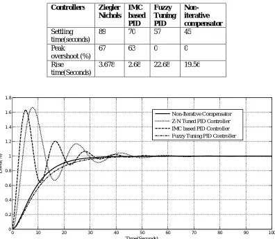
From fig 3 & Table VIII it is clearly shown that the Non-Iterative compensator shows better result with less settling time and zero peak overshoot when compared to conventional controller and intelligent controller.
Table VIII Comparison of controllers
Controllers Ziegler Nichols
IMC based PID
Fuzzy Tuning PID
Non-iterative compensator
Settling time(seconds)
89 70 57 45
Peak
overshoot (%)
67 63 0 0
Rise
time(Seconds)
3.678 2.68 22.68 19.56
Fig. 3 Response of Non-Interacting tank using various controllers
VIII. CONCLUSION
In this article, an attempt has been made to employ a simple Non-iterative Compensator as an alternative to PID controller for a Non-Interacting tank system. Z-N based PID controller tuning and IMC based PID controller tuning are found to exhibit a very high overshoot whereas fuzzy tuning PID exhibit larger settling time for the desired tank level. However the Non-iterative compensator is found to yield better results than these three tunings since the system settles down faster with zero overshoot. Moreover the compensator can be easily implemented in real time than the PID controller since it involves only three components. The effect of Non linearity such as saturation in PID controller can also be reduced to a greater extent since the gain Kc is very small compared to Kp of PID controller. Hence the compensator can be used as an effective controller to get the desired response in Non-Interacting tank system.
0 10 20 30 40 50 60 70 80 90 100
0 0.2 0.4 0.6 0.8 1 1.2 1.4 1.6 1.8
Time(Seconds)
L
ev
el
(%
)
REFERENCES
[1] Ashok Kumar, RajbirMorya and MunishVashishath, “Performance Comparison between Various Tuning Strategies: Ciancone, Cohen Coon & Ziegler- Nicholas Tuning Methods,” International Journal of Computers & Technology, vol.5, 2013.
[2] N. Deepa, S. Arulselvi and D. Rathikarani, “Comparative Study of MRAC and Fuzzy Control of Two-Tank Interacting Level Process,” International Journal of Engineering and Innovative Technology, vol.3, 2014.
[3] V.S Aditya, B. Shiva Kumar reddy, M. Surya prakashrao and V.L.N. sastry, “Tuning of PID Controller for a Multi Capacity Tank Systems by Different Methods,” International Journal of Advanced Research in Electronics and Communication Engineering, vol.1, 2012.
[4] FarhadAslam and MohdZeeshanHaider, “An Implementation and Comparative Analysis of PID Controller and their Auto Tuning Method for Three Tank Liquid Level Control,” International Journal of Computer Applications, vol.21, pp. 42-45, 2011.
[5] J. Arulvadivu, N. Divya, S. Manoharan, “Integrated PID Based Intelligent Control For Three Tank System,” ARPN Journal of Engineering and Applied Sciences, vol.10, pp. 4013-4017, 2015.
[6] C. Ganesh and Sanjib Kumar Patnaik, “A simple first order compensator for brushless direct current drive based position control,” Journal of vibration and control, vol.21, 2015.
[7] R. Shanmugasundram, C. Ganesh, N. Yadaiah and K.J. Poornaselvan, “Compensator design by pole-zero adjustment for a typical position control system,” Information and Automation for Sustainability, 2008.
[8] George Stephanopoulos, “Chemical Process Control”.
[9] SujitAnandraoJagnade, Rohit Ashok Pandit and Arshad Ramesh Bagde, “Modeling, Simulation and Control of Flow Tank System,” International Journal of Science and Research (IJSR), 2013.
[10] Divya Krishnan, K. Saravanan and P. Harikrishnan, “Simulation of Zn Tuning Method for Adaptive PID Controller in Cylindrical Tank Level System Using Lab View,” International Journal of Electrical and Electronics Research, vol.3, pp. 12-21, 2014.
[11] S. SakinathNisa, R. Ramya and P. Aravind, “Implementation of Model Based Controller For a Non Linear Level Process,” International Journal of Science, Engineering and Technology Research (IJSETR), vol.3, pp. 591-594, 2014.
[12] T. Rajesh, S. Arunjayakar and S.G Siddharth, “Design and Implementation Of IMC Based PID Controller for Conical Tank Level Control Process,” International Journal Of Innovative Research In Electrical, Electronics, Instrumentation and Control Engineering, vol.2, pp. 2041-2045, 2014.
[13] S. Gomathy and T. Anitha, “Analysis of pH process using Model Reference Adaptive Controller,” International Journal of Innovative Research in Technology, vol.1, pp. 90-95, 2014.
[14] S. Gomathy and T. Anitha, “Deaerator Storage Tank Level &Deaerator Pressure Control Using Soft Computing,” International Journal For Science and Advance Research In Technology, vol.1, pp. 137-142, 2015.
[15] M. Ramesh Patnaik, JayanathKappala, Varshitha Prakash and P. DurgaPrasada Rao, “Studies on Performance Improvement of Control Algorithms for Multi tank Interactive Level Systems by Fuzzy 1 and Fuzzy 2 Approaches,” International Journal of Emerging Trends in Engineering and Development, vol.1, 2015.
[16] Pedro Albertos and Antonio Sala, “Fuzzy Logic Controller, Advantages and Drawbacks,” 1998.
[17] C. Ganesh, S. Jeba, R. Saranya, S. Geethu, S.K. Patnaik, “A Non-Iterative Controller Design for a BLDC Drive System,” International Conference on Advances in Recent Technologies in Communication and Computing, pp. 141-145, 2009.