International Journal of Research (IJR)
e-ISSN: 2348-6848, p- ISSN: 2348-795X Volume 2, Issue 12, December 2015Available at http://internationaljournalofresearch.org
A Novel Fuzzy Based Modeling and Control of Direct
Control Variable Speed Wind Turbine with Interior
Permanent Magnet Synchronous Generator
Boyapati Sagar
PG Scholar, Nova College Of Engineering And Technology Jangareddy Gudem , Department Of Electrical And Electronics Engineering , JNTUK Andhrapradesh, India.
Miss D.Kamala
Nova College Of Engineering And Technology Jangareddy Gudem , Department Of Electrical And Electronics Engineering , JNTUK Andhrapradesh, India.
Abstract:
This paper proposes a noval fuzzy based drive on several aspects of modelling and control of interior permanent magnet (IPM) synchronous generator based grid connected variable speed wind turbine with maximum power extraction (MPE). In this method, the requirement of the continuous rotor position is eliminated as all the calculations are done in the stator reference frame. This thesis presents simple practical methods of determining parameters such as magnet flux, and, d- and q-axes inductances of an IPM synchronous
generator. The Fuzzy based direct control scheme
is simpler and can eliminate some of the drawbacks of traditional indirect vector control
scheme. The proposed control scheme is
implemented in MATLAB/Simpower systems and the results show that the controller can operate under constant and varying wind speeds. Finally, a sensorless speed estimator is implemented, which enables the wind turbine to operate without the mechanical speed sensor. The simulation and experimental results for the sensorless speed estimator are presented.
Index Terms—Direct control; interior permanent magnet (IPM) synchronous generator; sensorless speed estimator; Fuzzy
INTRODUCTION
The wind energy will play a major role to meet the renewable energy target worldwide, to reduce the dependency on fossil fuel, and to minimize the impact of climate change. Currently, variable speed wind turbine technologies dominate the world market share due to their advantages over fixed speed generation such as increased energy capture, operation at maximum power point, improved efficiency, and power quality [1]. Most of these wind turbines use doubly fed induction generator (DFIG) based variable speed wind turbines with gearbox [1]–[3]. This technology has an advantage of having power electronic converter with reduced power rating (30% of full rated power) as the converter is connected to the rotor circuit. However, the use of gearbox in these turbines to couple the generator with the turbine causes problems. Moreover, the gearbox requires regular maintenance as it suffers from faults and malfunctions [4].
International Journal of Research (IJR)
e-ISSN: 2348-6848, p- ISSN: 2348-795X Volume 2, Issue 12, December 2015Available at http://internationaljournalofresearch.org
and efficiency [5], [6]. The previous works done on PMSGbased wind turbines are mostly based on surface permanent magnet-type synchronous generator [7]–[9]. Very few works have been done so far on interior PMSG-based wind turbines, which can produce additional power by exploiting their rotor saliency [10]. It can also be operated over a wide speed range (more than rated speed) byflux weakening, which will allow constant power-like operation at speeds higher than the rated speed [10], [11]. This work is based on interior permanent magnet-type synchronous generator-based variable speed wind turbine. There are different control strategies reported in the literature for permanent synchronous generator-based variable speed wind turbine such as switch-mode boost rectifier (uncontrolled diode rectifier cascaded by a boost dc–dc chopper) [6], [12], [13], three-switch pulsewidth modulation (PWM) rectifier [14], and six-switch vector-controlled PWM rectifier [6], [10], [11], [15]. The control of PMSG-based variable speed wind turbine with switch-mode rectifier has the merit of simple structure and low cost because of only one controllable switch. However, it lacks the ability to control generator power factor and introduces high harmonic distortion, which affects the generator efficiency [8], [14]. Moreover, this scheme introduces high voltage surge on the generator winding which can reduce the life span of the generator [16]. Traditional vector control scheme, as shown in Fig. 1, is widely used in modern PMSG-based variable speed wind energy conversion system [6], [10], [11], [15]. In this scheme, the generator torque is controlled indirectly through current control. The output of the speed controller generates the - and – axes current references, which are in the rotor reference frame. The generator developed torque is controlled by regulating the currents and according to the generator torque equation.
For high performance, the current control is normally executed at the rotor reference frame, which rotates with the rotor. Therefore, coordinate transformation is involved and a
position sensor is, thus, mandatory for the torque loop. All these tasks introduce delays in the system [17], [18]. Also, the torque response under this type of control is limited by the time constant of stator windings [17].
In this paper, a direct control strategy is implemented where coordinate transformations are
not required as all the calculations are done in stator reference frame. Thus, the requirement of
continuous rotor position ( ) is eliminated.
This method is inherently sensorless and have several advantages compared with the traditional indirect vector control scheme [19]– [22]. However, a speed sensor is required only for speed control loop. Therefore, a sensorless speed estimator is proposed and implemented in this paper to estimate the speed without a mechanical sensor.
MODELING OF PROPOSED THORY WIND TURBINE MODEL AND MAXIMUM
POWER EXTRACTION
The power captured by the wind turbine is given by [6]
(1)
International Journal of Research (IJR)
e-ISSN: 2348-6848, p- ISSN: 2348-795X Volume 2, Issue 12, December 2015Available at http://internationaljournalofresearch.org
turbine rotor in mechanical (rad/s), and is the radius of the turbine (m).
(2)
The wind turbine can produce maximum power when the turbine operates at maximum (i.e., at ). Therefore, it is necessary to keep the rotor speed at an optimum value of the tip speed ratio . If the wind speed varies, the rotor speed should be adjusted to follow the change [6]
The target optimum power from a wind turbine is given by
(3)
Where
(4)
And
(5)
Fig.2. Mechanical power generated by the turbine as a function of the rotor speed for different wind speeds.
The optimum torque can be given by
(6) The mechanical rotor power versus rotor speed for varying wind speeds is shown in Fig. 2. The optimum power curve ( ) is also shown in Fig. 2, which shows how maximum energy can be captured at different wind speeds. The purpose of the controller is to keep the turbine operating on this curve, as thewind speed changes [6]. There is always a matching rotor speed that produces optimum power for a particular wind speed. If the controller can properly follow the optimum curve, the wind turbine will produce maximum power at any speed within the allowable range. The optimum torque can be calculated from the optimum power given by (6).
IPM SYNCHRONOUS GENERATOR
MODEL
The machine model in reference frame, which is synchronously rotating with the rotor, where axis is aligned with the magnet axis and -axis is orthogonal to --axis, is usually used for analyzing the interior permanent magnet (IPM) synchronous machine [23]. The - and -axes voltages of PMSG can be given by
(7)
(8)
The d- and q-axesflux linkages are given by
(9)
International Journal of Research (IJR)
e-ISSN: 2348-6848, p- ISSN: 2348-795X Volume 2, Issue 12, December 2015Available at http://internationaljournalofresearch.org
The torque equation of the PMSG can be written as
(11)
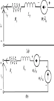
In (7)–(11), , , , , , and are the - and -axes stator voltages, currents, and inductances, respectively, is the stator resistance, is the rotor speed in rad/s, is the magnetflux, is the number of pole pairs, and is the operator . Fig. 3 shows the model of IPM synchronous generator. The first
Fig. 3. dq-model of IPM synchronous generator: (a) d-axis equivalent circuit and (b) q-axis equivalent circuit.
Fig. 4. Proposed direct control scheme for the IPM generator side converter.
term in the torque equation (11) is the excitation torque that is produced by the interaction of permanent magnetflux and and is independent of . The second term is the reluctance torque that is proportional to the product of and and to the difference between and . For the surface PMSG, the reluctance torque is zero since , while for the IPM synchronous generator, higher torque can be induced for the same and ,if( ) is larger. This is one of the advantages of IPM synchronous generator over surface PMSG.
The d- and q-axes current references can be expressed as
(12)
(13)
PROPOSED DIRECT CONTROL SCHEME FOR IPM SYNCHRONOUS GENERATOR
The direct control scheme for IPM synchronous generator is shown in Fig. 4. In this scheme, current controllers are not used. Instead, theflux linkage and torque are controlled directly. The torque and flux are controlled using two hysteresis controllers
International Journal of Research (IJR)
e-ISSN: 2348-6848, p- ISSN: 2348-795X Volume 2, Issue 12, December 2015Available at http://internationaljournalofresearch.org
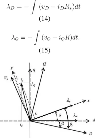
voltage vectors can be selected by using a switching-voltage vector lookup table, as shown in Table I. The selection of the voltage space vectors can be determined by the position of the statorflux linkage vector and the outputs of the two hysteresis comparators. The hysteresis control blocks compare the torque and flux references with estimated torque and flux, respectively. When the estimated torque/flux drops below its differential hysteresis limit, the torque/flux status output goes high. When the estimated torque/ flux rises above differential hysteresis limit, the torque/flux output goes low. The differential limits, switching points for both torque andflux, are determined by the hysteresis bandwidth [21], [24]. The appropriate stator voltage vector can be selected by using the switching logic to satisfy both the torque andflux status outputs. There are six voltage vectors and two zero voltage vectors that a voltage source converter can produce. The combination of the hysteresis control block (torque andflux comparators) and the switching logic block eliminates the need for a traditional PW modulator [20]. The optimal switching logic is based on the mathematical spatial relationships of statorflux, rotorflux, stator current, and stator voltage. These relationships are shown in Fig. 5 as rotor flux ( ) reference, stator flux ( ) reference, and stationary ( ) reference frames. The angle between the stator and rotor flux linkages is the load angle if the stator resistance is neglected. In the steady state, is constant corresponding to a load torque and both stator and rotorfluxes rotate at the synchronous speed. In the transient operation, varies and the stator and rotorfluxes rotate at different speeds. The magnitude of the stator flux is normally kept as constant as possible, and the torque is controlled by varying the angle between the statorflux vector and the rotorflux vector [20]. In direct torque andflux control scheme, the statorflux linkage is estimated by integrating the difference between the input voltage and the voltage drop across the stator resistance, as given by
(14)
(15)
Fig. 5. Stator and rotor flux linkages in different reference frames.
In the stationary reference frame, the statorflux linkage phasor is given by
and
(16) and the electromagnetic torque is given by
(17)
The torque equation in terms of and generator parameters is given by [24]
International Journal of Research (IJR)
e-ISSN: 2348-6848, p- ISSN: 2348-795X Volume 2, Issue 12, December 2015Available at http://internationaljournalofresearch.org
CONTROL OFSTATORFLUXLINKAGE BY SELECTING
PROPERSTATORVOLTAGEVECTOR
The stator voltage vector for a three-phase machine with balanced sinusoidally distributed stator windings is defined by the following equation:
(19)
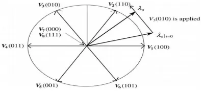
where the phase ―a‖ axis is taken as the reference position and , are the instantaneous values of line to neutral voltages. In Fig. 6, the ideal bidirectional switches represent the power switches with their antiparallel diodes. The primary voltages , , and are determined by the status of these three switches ( , , and ). Therefore, there are six nonzero voltage vectors , , , and and two zero voltage vectors and . The six nonzero voltage vectors are 60 apart from each other, as in Fig. 7. These eight voltage vectors can be expressed as
(21)
Where and Vdc= dc link voltage
Fig. 6. Rectifier connected to IPM synchronous generator
Fig. 7. Available stator voltage vectors.
A. Control of Amplitude of Stator Flux Linkage The statorflux linkage in the stationary reference frame can be given as
(21) Equation (21) can be written as
International Journal of Research (IJR)
e-ISSN: 2348-6848, p- ISSN: 2348-795X Volume 2, Issue 12, December 2015Available at http://internationaljournalofresearch.org
be selected. For example, whenis in region and is rotating in the clockwise direction
Fig. 8. Control of the amplitude of stator flux linkage
the voltage vectors pair and are selected to reverse the rotation of [20], [24]. B. Control of Rotation of The effect of two nonzero voltage vectors and is more complicated. It is seen from (22) that will stay at its original position when zero voltage vectors are applied. This is true for induction machine since the statorflux linkage is uniquely determined by the stator voltage, where the rotor voltages are always zero. In the case of an IPM synchronous generator,will change even when the zero voltage vectors are applied, since magnetflux continues to be supplied by the rotor and it will rotate with the rotor. In other words,should always be in motion with respect to the rotor flux linkage. Therefore, zero voltage vectors are not used for controllingin IPM synchronous machine [20], [24]. The electromagnetic torque is controlled by controlling the direction of rotation of, according to the torque equation (18). For counter clockwise operation, if the actual torque is smaller than the reference value, the voltage vectors that keeprotating in the same direction are selected. The angle increases as fast as it can and the actual torque increases as well. Once the actual torque is greater than the reference value, the voltage vectors that keeprotating in the reverse direction are selected instead of the zero voltage vectors. The angle decreases and torque decreases too. By selecting the voltage vectors in this way,is rotated all the time and its rotational direction is
determined by the output of the hysteresis controller for the torque [20], [24].The six-vector switching table for controlling both the amplitude and rotating direction ofis shown in Table I and is used for both the directions of operations. In Table I, and are the outputs of the hysteresis controllers forflux linkage and torque, respectively. If , then the actualflux linkage is smaller than the reference value. The same is true for the torque. – are the region numbers for the statorflux linkage positions.
IMPLEMENTATION OF DIRECT
CONTROL SCHEME FOR IPM
SYNCHRONOUS GENERATOR-BASED
WIND TURBINE
The direct control scheme for IPM synchronous generator is shown in Fig. 4, where the switching scheme used is shown in Table I. The three-phase variables are transformed into stationary
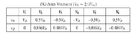
TABLE-II
axes variables. As shown in Fig. 4, torque error and flux error are the inputs to theflux hysteresis comparator and torque hysteresis comparator, respectively. The outputs of the hysteresis comparators ( ) are the inputs to the voltage-switching selection lookup table. As shown in Fig. 4, this scheme is not dependent on generator parameters except the stator resistance. Moreover, all calculations are in the stator reference frame and without any co-ordinate transformation.
A. Flux Linkage and Torque Estimation
The -axesflux linkage components and at the th sampling instant can be calculated as
International Journal of Research (IJR)
e-ISSN: 2348-6848, p- ISSN: 2348-795X Volume 2, Issue 12, December 2015Available at http://internationaljournalofresearch.org
(24)
where is the sampling time, the variables with subscript are their values at the th sampling instant, and the variables with are the previous samples. The -axes currents can be obtained from the measured three-phase currents and the -axes voltages are calculated from the measured dc-link voltages. Table II shows and axes voltages for the applied voltage vectors. The amplitude of the statorflux linkage is calculated from
and
(25) The developed torque is calculated from
(26)
The generator developed torque, in terms of stator and rotor flux linkage amplitudes, is also given by
(27)
RESULTS AND DISCUSSIONS
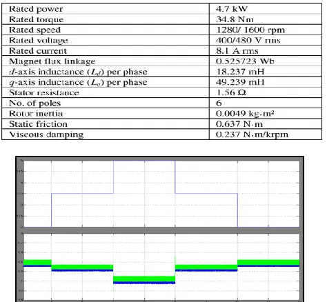
The direct control scheme for IPM synchronous generatorbased variable speed wind turbine shown in Fig. 4 is implemented in MATLAB/SimPowerSystemsdynamic system simulation software. The IPM synchronous generator data are given in Table III. Table I is used for switching the converter. The bandwidths of torque andflux hysteresis controllers are 10%
TABLE –III
Parameters of the IPM Synchronous generator
Fig. 9. Performance of the traditional indirect vector control scheme: (a) wind speed, (b) -axis current and its reference,
Fig. 9. Performance of the traditional indirect vector control scheme: -axis current and its reference, and (d) speed reference and measured speed.
International Journal of Research (IJR)
e-ISSN: 2348-6848, p- ISSN: 2348-795X Volume 2, Issue 12, December 2015Available at http://internationaljournalofresearch.org
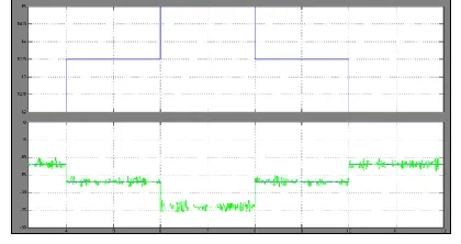
Fig. 10. Performance of the direct control scheme: (a) wind speed, (b) torque and
its reference.
Fig. 10. Performance of the direct control
scheme:,(c) flux linkage and its reference, and (d) speed reference and measured
been implemented in MATLAB/SimPowerSystemsusing the same IPM synchronous generator. MATLAB/SimPowerSystemswind turbine model is used in this work. The input to the wind turbine model is wind speed and the output is torque. A. Performance of the Indirect Vector Control Scheme Fig. 9 shows the performance of the indirect vector control of IPM synchronous generator-based variable speed wind turbine. The - and -axes currents and their references are shown in Fig. 9(b) and (c), respectively, and the wind speed in Fig. 9(a). It is seen that - and -axes currents follow their references quite well and regulate the generator current under different wind speeds. As shown in Fig. 9(d), the speed controller is able to regulate the speed for varying wind speeds.
B. Performance of Direct Torque and Flux Control Scheme Fig. 10 shows the performance of direct control scheme for IPM synchronous generator-based variable speed wind turbine. Fig. 10(a)–(d) shows the wind speed, torque response, fluxlinkage response, and speed response, respectively. As shown in Fig. 10(b) and (c), the torque andflux linkages are following these references quite well and regulate the torque andflux of the generator at different wind speeds. Fig. 10(d) shows the speed response, where the measured speed follows the reference speed well and the speed controller regulates the generator speed under varying wind conditions.
TABLE-IV
COMPARISON OF INDIRECT VECTOR CONTROL AND DIRECT CONTROL
SCHEMES
International Journal of Research (IJR)
e-ISSN: 2348-6848, p- ISSN: 2348-795X Volume 2, Issue 12, December 2015Available at http://internationaljournalofresearch.org
the comparison of indirect vector control and direct control schemes.
CONCLUSION
In this thesis, several aspects of modelling and control of Fuzzy Based interior permanent magnet synchronous generator based grid connected variable speed wind turbine is presented. Both the vector and direct control strategies are addressed for IPM synchronous generator based variable speed wind turbines are investigated. The impacts and issue associated with grid integration of wind farm are also studied. The proposed direct control scheme possesses several advantages compared with indirect vector control scheme, such as: 1) lesser parameter dependence; 2) torque andflux control without rotor position and PI controller which reduce the associated delay in the controllers; and 3) sensorless operation without mechanical sensor. The results show that the direct based fuzzy controller can operate under varying wind speeds. However, direct control scheme has the problem of higher torque ripple that can introduce speed ripples and dynamic vibration in the power train. The methods to minimize the torque/ speed ripples need to be addressed by fuzzy bassed control technique. The simulation and experimental results for the sensorless speed estimator are presented, and the results show that the estimator can estimate the generator speed quite well with a very small error.
REFERENCES
[1] S. Müller, M. Deicke, and R. W. D. De Doncker,―Doubly fed induction generator system for wind turbines,‖IEEE Ind. Appl. Mag., vol. 8, no. 3, pp. 26–33, May 2002.
[2] J. Hu, H. Nian, H. Xu, and Y. He,―Dynamic modeling and improved control of DFIG under distorted grid voltage conditions,‖IEEE Trans. Energy Convers., vol. 26, no. 1, pp. 163–175, Mar. 2011.
[3] M. Mohseni, M. S. M. Islam, and M. A. Masoum,―Enhanced hysteresisbased current regulators
in vector control of DFIG wind turbine,‖IEEE Trans. Power Electron., vol. 26, no. 1, pp. 223–234, Jan. 2011.
[4] H. Polinder, F. F. A. Van der Pijl, G. J. de Vilder, and P. J. Tavner, ―Comparison of direct-drive and geared generator concepts for wind turbines,‖ IEEE Trans. Energy Convers., vol. 3, no. 21, pp. 725–733, Sep. 2006.
[5] T. F. Chan and L. L. Lai, ―Permanent-magnet machines for distributed generation: A review,‖IEEE Power Engg. Annual Meeting, Tampa, FL, USA, Jun. 24–28, 2007, pp. 1–6.
[6] M. E. Haque, M. Negnevitsky, and K. M. Muttaqi,―A novel control strategy for a variable-speed wind turbine with a permanent-magnet synchronous generator,‖ IEEE Trans. Ind. Appl., vol. 46, no. 1, pp. 331–339, Jan./Feb. 2010.
[7] R. Esmali and L. Xu,―Sensorless control of
permanent magnet generator in wind turbine
application,‖IEEE Industry Applications Society Annual Meeting, Tampa, FL, USA, Oct. 8–12, 2006, pp. 2070–2075.
[8] M. Chinchilla, S. Arnaltes, and J. C. Burgos,―Control of permanent-magnet generators applied to variable-speed wind-energy systems connected to the grid,‖IEEE Trans. Energy Convers., vol. 21, no. 1, pp. 130–135, Mar. 2006.
[9] S. M. Deghan, M. Mohamadian, and A. Y. Varjani,―A new variable-speed wind energy conversion system using permanent-magnet synchronous generator and Z-source inverter,‖IEEE Trans. Energy Convers., vol. 24, no. 3, pp. 714–724, Sep. 2009.
[10] S. Morimoto, H. Nakayama, M. Sanada, and Y. Takeda,―Sensorless output maximization control for
variable-speed wind generation system using
IPMSG,‖IEEE Trans. Ind. Appl., vol. 41, no. 1, pp. 60– 67, Jan./Feb. 2005.
International Journal of Research (IJR)
e-ISSN: 2348-6848, p- ISSN: 2348-795X Volume 2, Issue 12, December 2015Available at http://internationaljournalofresearch.org
[12] C. N. Bhende, S. Mishra, and S. G. Malla,―Permanent magnet synchronous generator based standalone wind energy supply system,‖ IEEE Trans. Sustain. Energy, vol. 2, no. 4, pp. 361–373, Oct. 2011.
[13] S. M. R. Kazmi, H. Goto, H. J. Guo, and O. Ichinokura,―A novel algorithm for fast and efficient speed-sensorless maximum power point tracking in wind energy conversion systems,‖IEEE Trans. Ind. Electron., vol. 58, no. 1, pp. 29–36, Jan. 2011.
[14] S. Zhang, K. J. Tseng, D. M. Vilathgamuwa, T. D. Nguyen, and X. Y. Wang, ―Design of a robust grid interface system for PMSG-based wind turbine generators,‖ IEEE Trans. Ind. Electron., vol. 58, no. 1, pp. 316–328, Jan. 2011.
[15] A. Uehara, A. Pratap, T. Goya, T. Senjyu, A. Yona, N. Urasaki, and T. Funabashi,―A coordinated control method to smooth wind power fluctuation of a PMSG-based WECS,‖ IEEE Trans. Energy Convers., vol. 26, no. 2, pp. 550–558, Jun. 2011.
[16] K. Nishida, T. Ahmed, and M. Nakaoka,―A cost-effective high-efficiency power conditioner with simple MPPT control algorithm for wind-power grid integration,‖IEEE Trans. Ind. Appl., vol. 47, no. 2, pp. 893–900, Mar. 2011.
[17] M. F. Rahman, L. Zhong, and K. W. Lim, ―A direct torque controlled interior permanent magnet
synchronous motor drive incorporating field
weakening,‖ IEEE Trans. Ind. Appl., vol. 34, no. 6, pp. 1246–1253, Nov. 1998.
[18] I. Takahashi and T. Noguchi,―A new quick response and high efficiency control strategy of an induction motor,‖IEEE Trans. Ind. Appl., vol. IA-22, no. 5, pp. 820–827, Sep. 1986.
[19] I. Takahashi and Y. Ohmori,―High-performance direct torque control of an induction motor,‖IEEE Trans. Ind. Appl., vol. 25, no. 2, pp. 257–264, Mar./ Apr. 1989.
[20] L. Zhong, M. F. Rahman, and K. W. Lim,―Analysis of direct torque control in permanent magnet synchronous motor drives,‖ IEEE Trans. Power Electron., vol. 12, no. 3, pp. 528–536, May 1997.
[21] M. F. Rahman, L. Zhong, M. E. Haque, and M. A. Rahman,―A direct torque controlled interior permanent magnet synchronous motor drive without a speed sensor,‖IEEE Trans. Energy Convers., vol. 18, no. 1, pp. 17–22, Mar. 2003.
[22] L. Tang, L. Zhong, M. F. Rahman, and Y. Hu,―A novel direct torque control for interior permanent magnet synchronous machine drive system with low ripple in flux and torque andfixed switching frequency,‖IEEE Trans. Power Electron., vol. 19, no. 2, pp. 346–354, Mar. 2004.
[23] P. C. Krause, O. Wasynczuk, and S. D. Sudhoff,
Analysis of Electrical Machinery and Drive
System.Piscataway, NJ, USA: IEEE Press, 2002.
[24] M. E. Haque and M. F. Rahman,Permanent
Magnet Synchronous Motor Drives: Analysis,
Modeling and Control.Germany: VDM Verlag, 2009.
[25] H. Zhu, X. Xiao, and Y. Li,―Torque ripple reduction of the torque predictive control scheme for permanent-magnet synchronous motors,‖IEEE Trans. Ind. Electron., vol. 59, no. 2, pp. 871–877, Feb. 2012.
![2 [(2,4 Dimethylphenyl)iminomethyl] 6 methylphenol](data:image/gif;base64,R0lGODlhAQABAIAAAP///wAAACH5BAEAAAAALAAAAAABAAEAAAICRAEAOw==)