IJEDR1402128
International Journal of Engineering Development and Research (www.ijedr.org)2090
Harmonic Reduction of Doubly Fed Induction
Generator Connected To the Grid
1
Jadav Pankaj C,
2Belim Firdaus,
1P.G. Student (Electrical Power System), 2 P.G. Student (Electrical Power System) 1Electrical Engineering Department,
1
V.V.P. Engineering College, Rajkot, India
1[email protected], 2[email protected]
________________________________________________________________________________________________________
Abstract— Now a day penetration of renewable energy sources is increasing day by day and wind energy system is leading
in all this. DFIG with two levels AC/DC/AC converter is used with one as rotor side converter and other as the grid side converter. Rotor side converter controls the voltage and frequency of the DFIG whereas the grid side converter is there to control the DC link voltage. The main problem of the DFIG is harmonic as it contain two converter.to control the harmonic constant instantaneous power control strategy is used to control the harmonics.
Index Terms—DFIG, AC/DC/AC CONVERTER, FILTER, MATLAB
________________________________________________________________________________________________________
I.INTRODUCTION
Greenhouse gas reduction has been one of the crucial and inevitable global challenges, especially for the last two decades as more evidences on global warming have been reported. This has drawn increasing attention to renewable energies including wind energy. With increased penetration of wind power into electrical grids, DFIG wind turbines are largely deployed due to their variable speed feature and hence influencing system dynamics. This has created an interest in developing suitable models for DFIG to be integrated into power system studies. The continuous trend of having high penetration of wind power, in recent years, has made it necessary to introduce new practices.
DFIG when used in the wind turbine then they maintain the amplitude and the frequency of their output power to be constant. The relation between the mechanical power and the wind speed is given by
(1)
Cp= performance co-efficient
= air density A=swept area (m2) V=wind speed
As the speed of the wind changes according to it the mechanical power changes and similar to it the electrical power also changes. Figure shows the graphical relation of the wind speed and the mechanical power in the per unit value.
Fig.1: Relation between mechanical power and wind speed
DFIG stator is directly connected to the grid and the rotor is connected to the grid using AC/DC/AC converter. In which there are two converters are used to control the frequency and voltage of the DFIG. Rotor side converter (RSC) is directly connected to the rotor of the DFIG. RSC control the voltage and the frequency of the DFIG.GSC (grid side converter) is used to maintain the DC link voltage constant.
0 5 10 15 20 25 30 35
0 0.5 1 1.5
Wind Turbine Characteristics (w = 1.2 pu, pitch angle increases by step of 2 deg.)
P
(
p
u
)
IJEDR1402128
International Journal of Engineering Development and Research (www.ijedr.org)2091
Rotor
Control
Stator
Induction generator Turbine
Pitch angle AC
DC AC
AC/DC/AC converter Crotor
Cgrid
Three-phase Grid
Vr Vgc
Pgc
Qgc
Fig.2: Power flow diagram of the DFIG
II.ROTOR SIDE CONVERTER
The actual voltage and current is measured and compared with the reference voltage and the error is transmitted to the PI controller that gives the direct axis reference current. From the turbine power characteristic curve we can measure the power Pr
and from the line voltage and the current we get the P and line losses Ploss are added. The error signal is another PI controller
which give us the quadrature axis reference current and from this we transfer error signal from it to the current controller (PI) which give us the Vr .
AC voltage measurement
Drop of Xs
AC current measurement
Power tracking
Power measurement
Power losses
PI controller (voltage measurement)
Power controller
Current controller V
I
Ir
Wr
V
I
Wr
Iac
Is and Ir
Vref
Vac
Vx
+
-+
+
-+
Pr
P
Ploss
Idr_ref
Idr
Iqr_ref
Iqr
Vr
Vdr and Vqr
Fig.3: RSC Control Strategy
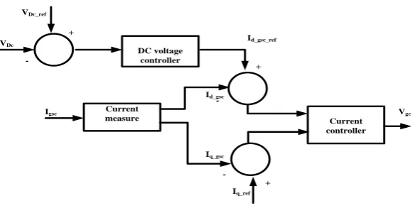
III.GRID SIDE CONVERTER
IJEDR1402128
International Journal of Engineering Development and Research (www.ijedr.org)2092
DC voltage controller
Current
measure Current
controller +
-+
+
-VDc
Igsc
VDc_ref
Id_gsc_ref
Id_gsc
Iq_gsc
Iq_ref
Vgc
Fig. 4: RSC Control Strategy
1. A measurement system measuring the d and q components of AC currents to be controlled as well as the DC voltage Vdc.
2. An outer regulation loop consisting of a DC voltage Regulator. 3. An inner current regulation loop consisting of a current Regulator.
The current regulator controls the magnitude and phase of the voltage generated by converter Cgrid (Vgc) from the Idgc_ref produced by the DC voltage regulator and specified Iq_ref reference. The current regulator is assisted by feed forward terms which predict the Cgrid output voltage.
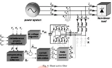
IV.FILTER DESIGN
Shunt active filter consist of two main block 1. The PWM converter
2. The active filter controller
PWM converter is responsible for power processing in synthesizing the compensating current that should drawn from the power system. Active filter controller is responsible for signal processing in determining in real time the instantaneous compensating current references, which are continuously passed to the PWM converter.
Fig.5: Basic configuration of shunt active filter
Instantaneous power calculation block calculate the instantaneous power of it. Power compensating selection block determine the behavior of the shunt active filter or it selects the parts of the real and imaginary power of the system that should be compensated by the shunt active filter. DC voltage regulator determine an extra amount of real power, represented by Ploss that
IJEDR1402128
International Journal of Engineering Development and Research (www.ijedr.org)2093
Fig. 6: Shunt active filter
According to the [3] the harmonic present in the DFIG is nearly equal to the 44.03 %. With the use of the shunt active filter (constant instantaneous current control) we get the harmonic nearly equal to the 4.12 %
V.SIMULATION OF DFIG USING SHUNT ACTIVE FILTER
Simulation shows the DFIG with its control strategy and filter.
Fig.7: Simulation of DFIG with filter
A. Simulation result of the voltage and current
Turbine and Drive Train
Wind Turbine Control
Wound-Rotor Induction Generator AC-DC-AC Converter Average Model Outputs FILT ER 1 m 3 C 2 B 1 A W_wt (pu) Pitch angle (deg) Wind speed (m/s)
Tt (pu)
Wi nd T urbi ne
A B C a b c Vnom _r/Vnom Z=0% s -+ Vbc_rc s -+ Vbc_gc s -+ Vab_rc s -+ Vab_gc
-K-Power base for the Generator
[Iabc_stator]
[Iabc_gri d_conv] [Vabc_B1]
[Vdc_V]
[Iabc_rotor]
[T em ] [Pi tch_deg] [Uctrl _rotor_conv]
[Uctrl _gri d_conv]
[AsyncM ac_si g]
[PQ_pu]
[Vabc_gri d_conv]
[Vabc_rotor]
[wr]
[angl e_rotor_rad]
[T m ]
[Iabc_stator] [Iabc_stator] [Pi tch_deg] [Vabc_rotor] [Iabc_rotor] [Vabc_B1] [Iabc_gri d_conv]
[T urbi neSpeed] [AsyncM ac_si g]
[T em ]
[PQ_pu] [Vabc_gri d_conv]
[Vdc_V] [Iabc_gri d_conv] [Iabc_rotor]
[T m ]
[Iabc_gri d_conv]
[Pi tch_deg] [Uctrl _rotor_conv]
[wr]
[Vabc_B1]
[T m ] [wr] [Uctrl _gri d_conv]
[angl e_rotor_rad] [Iabc_rotor]
[Vdc_V]
[wr]
A B C
Filter Q=50 Port5 Port2 Port4 Port1 Port3 Port6 T_wt (pu)
Generator speed (pu) W_wt (pu) T_shaf t (pu)
Dri ve T rai n
Uav g_grid_conv Uav g_rotor_conv Iabc_grid_conv _pu Iabc_rotor_pu Vab_gc Vbc_gc Vab_rc Vbc_rc Vdc
Converter average m odel
Vabc_B1 Iabc_stator Iabc_grid_conv Iabc_rotor Vdc_V Qref angle_rotor_rad wr Uctrl_grid_conv Uctrl_rotor_conv Pitch_deg PQ_pu Control
A B C A B C
Choke Vabc A B C a b c B_rotor_conv Vabc Iabc A B C a b c B_gri d_conv Vabc A B C a b c B1 m A B C a b c Tm Asynchronous Machine pu Units 2 Qref_pu 1 Wi nd (m /s)
Pitch_deg PQ_pu Tem_pu Tm_pu TurbineSpeed_pu Vdc_V Iabc_grid_conv _pu Vabc_grid_conv _pu Iabc_rotor_pu Vabc_rotor_pu Iabc_stator_pu Vabc_stator_pu
<Electromagnetic torque Te (pu)> <Rotor speed (wm)>
<Rotor current ir_c (pu)> <Rotor current ir_b (pu)> <Rotor current ir_a (pu)> <Stator current is_c (pu)> <Stator current is_b (pu)> <Stator current is_a (pu)> <Rotor angle thetam (rad)>
IJEDR1402128
International Journal of Engineering Development and Research (www.ijedr.org)2094
Fig.8: Simulation result of DFIG
B. Harmonic content of the dfig with the filter
Fig.9: Harmonic content of the DFIG
VI. CONCLUSION
As discussed the doubly fed induction generator has ability to control the voltage and frequency as well as it maintains the voltage and frequency constant. In DFIG AC/DC/AC two converters are there one rotor side converter and other grid side converter. Rotor side converter controls the active and reactive power while the grid side converter maintains the DC link voltage constant. In the simulation of DFIG harmonic contain of [3] is reduced from the 44.03% to the 4.12%.
REFERENCES
[1] Omar Noureldeen “Behavior of DFIG Wind Turbines with Crowbar Protection under Short Circuit” International Journal of Electrical & Computer Sciences IJECS-IJENS Vol: 12 No: 03 June 2012
[2] Wei Qiao, Ronald G. Harley “Effect of Grid-Connected DFIG Wind Turbines on Power System Transient Stability” 2008 IEEE
0 0.02 0.04 0.06 0.08 0.1
-1 0 1
Selected signal: 5 cycles. FFT window (in red): 5 cycles
Time (s)
0 5 10 15 20
0 20 40 60 80
Harmonic order
Fundamental (50Hz) = 0.536 , THD= 4.12%
M
a
g
(
%
o
f
F
u
n
d
a
m
e
n
ta
l)
0 0.01 0.02 0.03 0.04 0.05 0.06 0.07 0.08 0.09 0.1
-0.4 -0.2 0 0.2 0.4
V
o
lt
a
g
e
(
P
U
)
0 0.01 0.02 0.03 0.04 0.05 0.06 0.07 0.08 0.09 0.1
-2 -1 0 1 2
Time
C
u
rr
e
n
t
(P
U
IJEDR1402128
International Journal of Engineering Development and Research (www.ijedr.org)2095
Inverter” 2012 International Conference on Computing, Electronics and Electrical Technologies [ICCEET]
[4] Abdoulaye Mamadie Sylla, Mamadou Lamine Doumbia “Maximum Power Control of Grid-connected DFIG-Based Wind Systems” 2012 IEEE Electrical Power and Energy Conference
[5] Hyong Sik Kim, Dylan Dah-Chuan Lu “Review on Wind Turbine Generators and Power Electronic Converters with the Grid-Connection Issues”
[6] J. L. Elizondo, M. E. Macías, and O. M. Micheloud “Matrix Converters Applied to Wind Energy Conversion Systems, Technologies and Investigation Trends” 2009 Electronics, Robotics and Automotive Mechanics Conference
[7] Ashwani Kumar, Sanjay K. Jain “A Review on the Operation of Grid Integrated Doubly Fed Induction Generator” International Journal of Enhanced Research in Science Technology & Engineering, ISSN: 2319-7463 Vol. 2 Issue 6, June-2013, pp: (25-37)
[8] Ji-Heon Lee, Jong-Kyou Jeong, Byung-Moon Han, Nam-Sup Choi and Han-Ju Cha “DFIG Wind Power System with a DDPWM Controlled Matrix Converter” Journal of Electrical Engineering & Technology Vol. 5, No. 2, pp. 299~306, 2010
[9] S. Jia, X. Wang and K.J.Tseng “Matrix Converters for Wind Energy Systems” 2007 IEEE
[10] K.Ghedamsi, D.Aouzellag, E.M.Berkouk “Application of Matrix Converter for Variable Speed Wind Turbine Driving an Doubly Fed Induction Generator” 2006 International Symposium on Power Electronics, Electrical Drives, Automation and Motion