75
Effect Of Dimple Diameter On Heat Transfer
Enhancement Of Double Pipe Heat Exchanger
Using Dimpled Twisted Tape
Sanjay Kumar Singh, Arvind Kumar
Abstract: The objective of this communication is to carry outnumerical studyof heat transfer and friction factor in a double pipe heat exchanger (DPHE) counter-flowarrangementusing twisted tape with dimple inserts. The study investigated the effects of twisted tapes with dimples insert of different dimple diameters of 3mm,5mm and 7mm at D/H ratio 3. The numerical analysis revealed that the value of Nusselt number was maximum for dimple diameter 5mm and it is 1.37 - 1.46, 1.19 - 1.24 and 1.10 - 1.18 times greater than the twisted tape without dimple,for twisted tape with dimple diameter 3mm and with 7mm respectively. The friction factor was found to be directly proportional to the diameter of the dimple.For tube fitted with twisted tape without dimple,for twisted tape with dimples of diameter 3mm, 5mm and 7mm,the values were 3.34 - 3.63, 3.62 - 4.36, 4.86 - 5.10 and 5.76 - 6.06 times greater than the plain tube. The results emphatically reflected the positive impact of twisted tapes with dimple inserts on heat transfer enhancement in DPHE.
Keywords: Twisted tape with dimple insert, DPHE, Nusselt Number, Friction factor, Thermal performance factor
————————————————————
1.
INTRODUCTIONAND
LITERATURE
REVIEW
The alteration, application and recovery of energy in every industrial, commercial and home application consist of numerous heat exchange processes. Some common illustrations are steam formation and condensation in power plant and various co-generation plants, sensible heating and cooling of viscous fluid in thermal processing of chemical, medicinal, and agronomic produces, phase change process of refrigerant in air conditioning and refrigeration, gas flow heating in manufacturing, waste heat utility, cooling of various engines and turbo- machinery systems, cooling of electrical and electronics equipment and gadgets. Improved methods and techniques of heat exchange, over and above in usual or standard practice, can significantly enhance the thermal performance of such applications as well as the cost effectiveof their design and operation. (DPHE) or concentric tube heat exchanger is one of the most simple in terms of design and isbroadly used in food provisions ,chemical, gas industries and refineries [1, 2]. However heat exchangers are designed to attain maximum effectiveness and heat transfer along with minimum pressure drop, volume, weight and cost. Over the past decades, various techniques have been developed for these purposes. In general, these techniques can be classified as active, passive and compound. Out of these, passive techniques are mostly used as they do not use external power input. The thermo-hydraulic performance can be increased significantly by using turbulators which increase the turbulence of fluid flow by producing secondary flow [2].
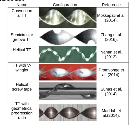
Since 1960s, a vast number of theoretical and experimental analysis and researches have been performed to study the performance of a heat exchanger with wide variety of twisted tapes [3-7]. Twisted tapes can be manufactured in numerous designs such as typical, perforated, notched, jagged, center-cleared, V-cut, serrated, square cut, helical screw, etc. using different techniques as shown in Table 1. Yu X et al. [4] used straight strip insert with elliptical teeth and broken edge on both sides, to eliminate the difficulty faced in manufacturing twisted tape with elliptical teeth. It was demonstrated that this kind of insert can efficiently work at a flow speed of 0.5 m/s and the value of heat transfer coefficient (h) was enhanced by 171%. Some of the different configuration of twisted tape is shown below.
Table 1. Schematic geometry of different configurations of twisted tape
Name Configuration Reference
Convention
al TT Mokkapati et al.
(2014).
Semicircular groove TT
Zhang et al. (2016).
Helical TT
Nanan et al. (2013). TT with
V-winglet Promvonge et
al. (2014). Helical
screw tape Suhas et al.
(2014). TT with
geometrical progression
ratio
Maddah et al.(2014).
Murugesan et al. [11-13] experimentally studied the outcomes of square-cut twisted tape, trapezoidal-cut twisted tape and V-cut twisted tape on the heat transfer and friction factor
__________________________
aResearch Scholar,Department of Mechanical Engineering, Maulana Azad National Institute of Technology ,Bhopal bAssistant Professor, Department of Mechanical Engineering,
characteristics in tubes and hence reported that heat transfer enhanced by 1.2 times at low Reynolds number. Guo et al.[14]numerically investigated the effect of suitable central clearance ratio of twisted tape on heat transfer .Zang et al.[15] numerically investigated the impact of different widthof helical screw-tape inserts on heat transfer along with friction factor and reported that heat transfer was enhanced by 212-351% and friction factor increased by 1020%. Dimple is one of the types of concavity which enhances the heat transferrate with comparatively lesser pressure drop.Terekhov et al. [16] performed experimentallyon single dimple (D/H= 2- 7.69, Re=10000-70000) and investigated its effect on heat transfer and aerodynamic resistance.Eiamsa-ard and Promvonge [17] investigated that the effect of free-spacing ratio helical tapeon Nusselt number at free spacing ratio of 0.5 yielded the best Nu, which was50% higher than that obtained using a plain tube. After a thorough literature review, it has been concluded that numerous researchers[19-30]have investigated various types of twisted tape inserts in their experimental and modelling studies. However no study has been done on the heat transfer by using twisted tape with dimple insert in a double pipe heat exchanger. The purpose of this work is to study the heat transfer and friction factor in a horizontal double pipe heat exchanger using twisted tape with dimpleinsert fordifferent diameter (D) at constant dimple diameter(D) to depth (H) ratio. In the present work, the effect of dimple diameter on heat transfer and pressure drop is numerically analysed. The Reynolds number ranges from 6000 to 14000 with hot/cold water as a flowing fluid. The result of heat transfer enhancement and pressure drop are obtained numerically have been graphically represented and discussed.
2.
PHYSICAL
MODEL
AND
NUMERICAL
METHOD
2.1 PHYSICALMODEL
In this work, a concentric double pipe heat exchanger with water as a flowing medium is shown in Figure 1. Hot water was made topass through the inner tube whereas cold water was made to pass through the annulus. For the double pipe heat exchanger,the inner tube comprised of copper with a thicknessof 2 mm, the inside diameter of the pipe was (d) 16 mm and length 2470 mm, while the outer tube was made up of GI with a thickness of 3 mm, inner diameter of 32 mm and length 2400 mm.The detailed information of the twisted tapes used, along with their three dimensional view is shown in figure 2.twisted tapes used for the study are made of aluminium of thickness 1mm and twist ratio of 4.0 for all cases. The effectiveness of the proposed twisted tape inserts with dimples, in achieving enhanced rate of heat transfer, has been evaluated on the basis of outlet temperature, surface temperature of inner tube and pressure drop. The variations in the physical properties of the twisted tape with dimples having diameter 3mm,5mm and7mm have been made at constant twist ratio of 4.0. The Reynolds number of the hot water, flowing through the inner tube, has been varied from 6000 to 14000. The Reynolds numbers used in this studyis depended on the hydraulic diameter of the tube and mean inlet velocity of the working fluid.The average inlet velocity boundary found by the specific Re is carried out at the inlet and a pressure outlet boundary is utilised. The flowing fluid flows into the tube with the length (z –direction) and nonslip boundary are used on the walls.
a) Front view b) Side View
Figure1.Schematic representation of test section.
Figure2. Twisted tape with dimples
NUMERICAL METHOD
In this work assumptions are made that, the flow is continuous, steady and incompressible and the gravitational effect is negligible. The second order discretization k-ꞓ realizable turbulence model with the fine mesh of 791200 elements is designated as the best simulation tactics. The residues of continuity, velocities and energy are observed to evaluate the convergence of computation where the convergence principle is set as 1x10⁻⁶. The follow-on conservation equations of mass, momentum and energy are specified as follows
(∂(ρui))/(∂xi )=0 (1) Momentum equation is represented as
̅̅̅̅̅̅ = −
+ (μ (
+
)) −
̅̅̅̅̅̅̅̅ (2) Energy equation is shown as
(u ρe + p ) = λ
(3)
where p is pressure, ρ is fluid density, T is fluid temperature, λ is thermal conductivity and μ is fluid viscosity respectively. The Re-Normalisation Group (RNG) version of k-ε model is used in this numerical study. The Turbulent kinetic energy k is
(ρku) = ((μ + ) λ
) + G − ρε (4) where ε is Turbulent dissipation energy and Gk is Turbulent kinetic energy production.
(ρεu) = ((μ + ) λ
) + ρC S − ρC √ (5)
G = μ S (6)
μ = ρC (7)
Cμ is not constant in k-ε realisable model. It is calculated from empirical relation. The calculation of Cμis given in detail in Ref. [18]. The model constants is
C = max[0.43, ], η = S , S = √2S S , C = 1.9, σ = 1, σ = 1.2
S_ij shows the rate of deformation of fluid element linearly.
`
77 S = +
(8)
METHOD VALIDATION
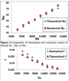
The Computational Fluid Dynamic Analysis has been carried out using ANSYS FLUENT 19.2. For the purpose of the study, analytical validation of the heat exchanger model has been carried out, and the Nusselt number and friction factor have been authenticated with Gnielinski correlation and Filonenko correlation, respectively. The present Nu values are paralleled with those based on Gnielinski with a maximum variation of ±6.7 % and f values reach to agreement with those obtained from Filonenko with a maximum variation of ±7.0 % .It is also recommended that the k-ꞓ realizable turbulence model is suitable for the computation in the present work. In short, this method is appropriate to predict the heat transfer and flowcharacteristics in this study.
Gnielinski correlation
Nuf=(f/8)(Re-1000)Prf/(1+12.7(f/8)1/2(Pr)2/3-1)x(1+(d/L)2/3)xC1 (9)
For liquid, C1= (Prf/Prw) 0.01 if Prf/Prw= 0.05 to 20 Filonenko correlation
f= (1.82logRe-1.64)-2 (10) PEC=(Nu/Nuo)/(f/fo)
1/3
(11)
Performance Evaluation Criteria (PEC) is defined as the ratio of the heat transfer within enhanced pipes against plain pipes to the friction coefficient in enhanced pipes against plain pipes. This ratio is an important factor in the heat transfer area and reveals the importance of heat transfer to pressure drop in the heat exchangers.
Figure 3.Comparison of theoretical and numerical values of Nusselt no. (Nu vs Re)
Figure 4.Comparison of theoretical and numerical values of friction factor (f vs Re)
3.
GRID INDEPENDENCE STUDY
To improve the computation precision, all hybrid (hexahedral &tetrahedral) mesh areused in all cases. The tetrahedral mesh is employed close to the dimples and protrusion in order to improve the mesh superiority to the greater extent. To maintain balance between the computation precision and resource required,a grid independency test is carried out to obtain a sensible grid as shown in Figure 5 and Table 2.It is shown that when mesh 6 is used, the relative differences of Nu and f are ±0.73% and ±0.8% in comparison with mesh 5respectively.
Figure 5: A sample of the geometry utilized in the computational fluid dynamics with the related meshing in this
study
Table 2
Grid Independence Study
Mesh Number of Element Nu Difference % f nce % Differe Mesh
1 159730 78.33 9.27 0.0072 4.55
Mesh
2 205443 79.98 7.35 0.0071 2.9
Mesh
3 266863 85.94 0.44 0.0071 3.7
Mesh
4 409202 86.35 0.02 0.0070 1.1
Mesh
5 571402 86.96 0.73 0.0069 0.8
Mesh
6 791200 86.33 Ref. 0.0069 Ref
Figure 6. Grid independence study
4.
RESULT AND DISCUSSION
The heat transfer and friction characteristics of plain tube, twisted tape without dimples and twisted tape with dimples
30 40 50 60 70 80
5000
7000
9000
11000
13000
15000
Nu
Re
Theoretical Nu
Numerical Nu
0.025
0.03
0.035
0.04
5000
7000
9000 11000 13000 15000
f
Re
Numerical f
Theoretical f
76 78 80 82 84 86 88
0 500000 1000000
Nu
Element No
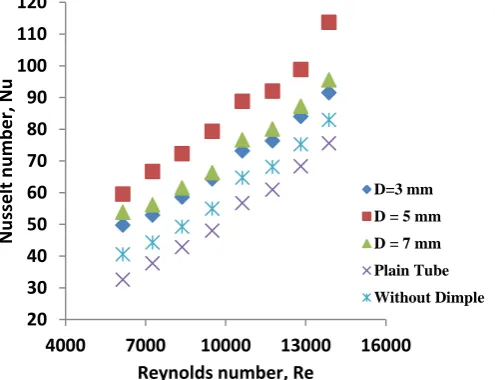
(D=3mm,5mm and 7mm) are given in Figure 7 and 8 respectively; where the effects of dimple on heat transfer enactment and frictional resistance are primarily considered. It can be seen that in all the cases Nusselt number increases with the increasing Reynolds number.When matched with a plain tube, twisted tape without dimples and with dimples actually enhances heat transfer. For the investigated range of Reynolds number , Nu in the tube with twisted tapewithout dimple and with dimples of diameter 3mm,5mm and 7mmwas 1.09-1.24,1.21-1.52,1.50-1.82 and1.26-1.65 times respectively greater than the plain tube.Nusselt number ratio decreases with increase in Reynolds number, it means twisted tape gives better result forlower value of Re (weak turbulence). It was found that the Nusselt number is maximum for dimple diameter 5mm and it is 1.19- 1.24, 1.10-1.18 and 1.37-1.46 times greater than the twisted tape with dimple diameter 3mm, 7mm and twisted tape without dimple respectively. The Nusselt number increases from dimple diameter 3mm to 5mm and it decreases from 5mm to 7mm of dimple diameter. This is due to some flow that is trapped at the bottom of the dimple and flow is separated by the protrusion.
Figure 7 .Variation of Nusselt number with Reynolds number for twisted tape with different dimple diameter and its comparison with plain tube and twisted tape without dimple
Deviation of friction factor with Reynolds number in the plain tube, twisted tape without dimples and twisted tape with dimples (D=3mm,5mm and 7mm) are given in Figure 8,where the effects of dimple diameter on friction resistance are considered. It can be seen that in all cases, friction factor is inversely proportional to the Reynolds number. Twisted tapes result higher friction factor than the plain tube. Over the range of Reynolds number investigated, friction factor in the tube fitted with twisted tape without dimple,twisted tape with dimples of diameter 3mm,5mmand 7mm was 3.34-3.63,3.62-4.36,4.86-5.10 and5.76-6.06 times greater than plain tube. Friction factor also depends on diameter of dimples and it is directly proportional to the dimple diameter. It is because dimple decreases the flow area and provides more contact surface.
Figure 8.Variation of Friction factor with Reynolds number for twisted tape with different dimple diameter and its comparison with plain tube and twisted tape without dimple.
Figure 9.Variation of Performance Evaluation Criteria (PEC) with Reynolds number for twisted tape with different dimple diameter and its comparison with twisted tape without dimple
Deviations of performance evaluation criteria(PEC) with Reynolds number in the tube without insert and in tubes with twisted tapes insert is shown in Figure 9.It can be seen from the Figure 9 that the PEC reduced with increase in Reynolds number.it shows that when Reynolds number increases the effect of twisted tape, on friction factor becomes more and more important with increasing Reynolds number in evaluation with Nusselt number. Over the investigated range of Reynolds number, PEC of twisted tape without dimple is least among all other arrangements; it shows that in this case friction factor is much prevailing overheat transfer. PEC of twisted tape with dimples of diameter 3mm, 5mm and 7mm are 1.15-1.23,1.27-1.40 and 1.04-1.17 times greater than the PECof tube fitted with twisted tape without dimple.
20 30 40 50 60 70 80 90 100 110 120
4000 7000 10000 13000 16000
Nu
sselt
n
u
mbe
r,
Nu
Reynolds number, Re
D=3 mm
D = 5 mm
D = 7 mm
Plain Tube
Without Dimple
0 0.05 0.1 0.15 0.2 0.25
4000 7000 10000 13000 16000
Fr
ict
ion
f
act
or
, f
Reynolds number, Re
D = 3 mm D = 5 mm D = 7 mm Plain Tube Without Dimple
0.6 0.7 0.8 0.9 1 1.1 1.2
5000 7000 9000 11000 13000 15000
Pe
rf
or
ma
n
ce
e
va
lu
ati
on
cr
iter
ia
,
PEC
Reynolds number, Re
D = 3 mm D = 5 mm
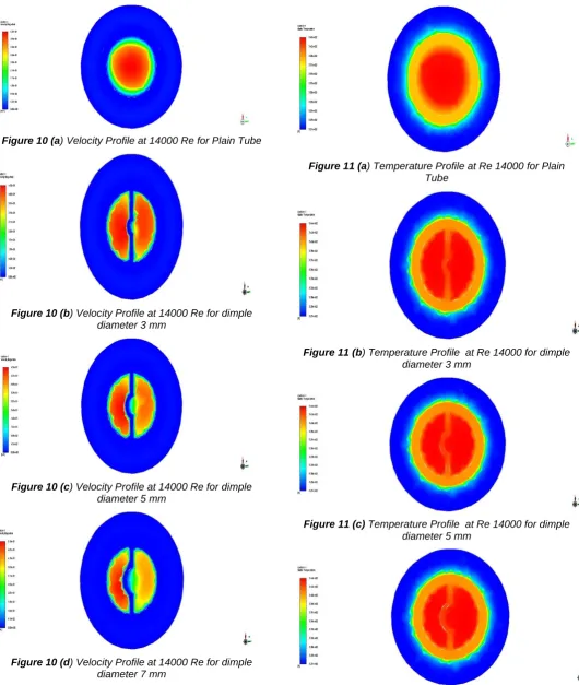
79 Figure 10 (a) Velocity Profile at 14000 Re for Plain Tube
Figure 10 (b) Velocity Profile at 14000 Re for dimple diameter 3 mm
Figure 10 (c) Velocity Profile at 14000 Re for dimple diameter 5 mm
Figure 10 (d) Velocity Profile at 14000 Re for dimple diameter 7 mm
Figure 11 (a) Temperature Profile at Re 14000 for Plain Tube
Figure 11 (b) Temperature Profile at Re 14000 for dimple diameter 3 mm
Figure 11 (c) Temperature Profile at Re 14000 for dimple diameter 5 mm
After seeing the numerical results, it was observed that the flow patterns at different Reynolds number are almost similar. Taking Re=14000 as an example. Above Figures 10-12provide the wall temperature distribution profiles and limit streamlines on particularcharacteristic heat transfer surfaces, including the tape wall and tube wall in order to give a clear information of the flow and the effect of dimples.
Figure 12 (a) Pressure Profile at Re 14000 for Plain Tube
Figure 12 (b) Pressure Profile at Re 14000 for dimple diameter 3 mm
Figure 12 (c) ) Pressure Profile at Re 14000 for dimple diameter 5 mm
Figure 12 (d) ) Pressure Profile at Re 14000 for dimple diameter 7 mm
5.
CONCLUSIONS
The effect of twisted tape inserts with dimple of different diameter on heat transfer and friction factor characteristics has been studied numerically. The conclusions can be summarized as follow: Over a range of Reynolds number investigated twisted tape inserts with dimples gives higher Nusselt number and friction factor in comparison with twisted tape inserts without dimple and plain tube. The Nusselt number increases as diameter of dimple increases from 3mm to 5mm and then decreases as diameter increases from 5mm to 7mm. This is due to some flow that is trapped at the bottom of the dimple and the flow is separated by the protrusion. Friction factor depends on diameter of dimple and it is directly proportional to the diameter of dimple. It is because dimples decreases the flow area and provides more contact surface. As the Reynolds number increases the effect of twisted tape with dimples on friction factor it becomes more and more significant with increasing Reynolds number in comparison with Nusselt number. Over the range of Reynolds number investigated, PEC of twisted tape without dimple is least among all other arrangements, it means that in this case friction factor is predominant over Nusselt number.
REFERENCES
[1] Hasanpour A, Farhadi M, Sedighi K. A review study on twisted tape inserts on turbulent flow heat exchangers: The overall enhancement ratio criteria. International communications in heat and mass transfer. 2014 Jul 1;55:53-62.
[2] Guo J, Fan A, Zhang X, Liu W. A numerical study on heat transfer and friction factor characteristics of laminar flow in a circular tube fitted with center-cleared twisted tape. International Journal of Thermal Sciences. 2011 Jul 1;50(7):1263-70.
[3] Omidi M, Farhadi M, Jafari M. A comprehensive review on double pipe heat exchangers. Applied Thermal Engineering. 2017 Jan 5;110:1075-90. [4] Yu X, Yu T, Peng D, Jiang S, Luo J. Twisted strip with
oblique teeth to efficiently remove fouling and enhance heat transfer at low flowing velocity [J]. Journal of Chemical Industry and Engineering (China). 2005;4.
81 [6] Zhang C, Wang D, Ren K, Han Y, Zhu Y, Peng X,
Deng J, Zhang X. A comparative review of self-rotating and stationary twisted tape inserts in heat exchanger. Renewable and Sustainable Energy Reviews. 2016 Jan 1;53:433-49.
[7] Nanan K, Yongsiri K, Wongcharee K, Thianpong C, Eiamsa-Ard S. Heat transfer enhancement by helically twisted tapes inducing co-and counter-swirl flows. International Communications in Heat and Mass Transfer. 2013 Aug 1;46:67-73.
[8] Promvonge P, Suwannapan S, Pimsarn M, Thianpong C. Experimental study on heat transfer in square duct with combined twisted-tape and winglet vortex generators. International Communications in Heat and Mass Transfer. 2014 Dec 1;59:158-65. [9] Patil S, Vijay Babu P. Experimental heat transfer and
friction factor studies through a square duct fitted with helical screw tapes. The Canadian Journal of Chemical Engineering. 2014 Apr;92(4):663-70. [10] Maddah H, Alizadeh M, Ghasemi N, Alwi SR.
Experimental study of Al2O3/water nanofluid turbulent heat transfer enhancement in the horizontal double pipes fitted with modified twisted tapes. International Journal of Heat and Mass Transfer. 2014 Nov 1;78:1042-54.
[11] Murugesan, P., Mayilsamy, K.and Suresh, S., Turbulent Heat Transfer and Pressure Drop in Tube Fitted with Square-cut Twisted Tape, Chinese J. Chem. Eng.,vol. 18,pp.609-617, 2010.
[12] Murugesan, P., Mayilsamy, K., Suresh, S.andSrinivasan, P.S.S., Heat transfer and pressure drop characteristics in a circular tube fitted with and without V-cut twisted tape insert, Int.Commun. Heat Mass Transf., vol.38,pp. 329-334,2011.
[13] Murugesan, P., Mayilsamy, K.and Suresh ,S., Heat Transfer and Friction Factor Studies in a Circular Tube Fitted with Twisted Tape Consisting of Wire-nails, Chinese J. Chem. Eng.,vol. 18 ,pp.1038-1042,2010.
[14] Guo J, Fan A, Zhang X, Liu W. A numerical study on heat transfer and friction factor characteristics of laminar flow in a circular tube fitted with center-cleared twisted tape. International Journal of Thermal Sciences. 2011 Jul 1;50(7):1263-70.
[15] X.Y.Zang, Z.C.Liu. W.Liu, Numerical studies on heat transfer and friction factor characteristics of tube fitted with helical screw-tape without core-rod inserts, International Journal of Heat and Mass Transfer. 2013, 60:490-498.
[16] Terekhov et al. [17] conducted the experimental investigation on the heat transfer and aerodynamic resistance of a single dimple (D/H= 2- 7.69, Re=10000-70000).
[17] Eiamsa-ard S, Promvonge P. Enhancement of heat transfer in a tube with regularly-spaced helical tape swirl generators. Solar energy. 2005 Apr 1;78(4):483-94.
[18] Terekhov VI, Kalinina SV, Mshvidobadze YM. Heat transfer coefficient and aerodynamic resistance on a surface with a single dimple. Journal of Enhanced Heat Transfer. 1997;4(2).
[19] Corcoles-Tendero JI, Belmonte JF, Molina AE, Almendros-Ibanez JA. Numerical simulation of the heat transfer process in a corrugated tube. International Journal of Thermal Sciences. 2018 Apr 1;126:125-36.
[20] Abed AM, Majdi HS, Hussein Z, Fadhil D, Abdulkadhim A. Numerical analysis of flow and heat transfer enhancement in a horizontal pipe with P-TT and V-Cut twisted tape. Case Studies in Thermal Engineering. 2018 Sep 1;12:749-58.
[21] Kunlabud S, Chuwattanakul V, Kongkaitpaiboon V, Promthaisong P, Eiamsa-ard S. Heat transfer in turbulent tube flow inserted with loose-fit multi-channel twisted tapes as swirl generators. Theoretical and Applied Mechanics Letters. 2017 Nov 1;7(6):372-8.
[22] Bhattacharyya S, Chattopadhyay H, Haldar A. Design of twisted tape turbulator at different entrance angle for heat transfer enhancement in a solar heater. Beni-Suef University Journal of Basic and Applied Sciences. 2018 Mar 1;7(1):118-26.
[23] Bhattacharyya S, Chattopadhyay H, Pal A, Bandyopadhyay S, Roy S. Numerical simulation of fluid flow and heat transfer enhancement in a circular wavy channel. Journal of Thermal Engineering and Applications. 2015 Jun 17;2(2):28-35.
[24] Bhattacharyya S, Chattopadhyay H, Bandyopadhyay S. Numerical study on heat transfer enhancement through a circular duct fitted with centre-trimmed twisted tape. International Journal of heat and Technology. 2016 Sep 1;34(3):401-6.
[25] Shaji K. Numerical analysis on a double pipe heat exchanger with twisted tape induced swirl flow on both sides. Procedia Technology. 2016 Jan 1;24:436-43.
[26] Sivakumar K, Mohankumar T, Rajan K. Numerical analysis of heat transfer characteristics with triangular cut twisted tape inserts. In AIP Conference Proceedings 2018 Nov 27 (Vol. 2039, No. 1, p. 020059). AIP Publishing.
[27] Salman SD, Kadhum AA, Takriff MS, Mohamad AB. CFD analysis of heat transfer and friction factor characteristics in a circular tube fitted with quadrant-cut twisted tape inserts. Mathematical problems in Engineering. 2013;2013.
[28] Budak N, Yucel HL, Argunhan Z. Experimental and numerical investigation of the effect of turbulator on heat transfer in a concentric-type heat exchanger. Experimental Heat Transfer. 2016 May 3;29(3):322-36.
[29] Piriyarungrod N, Kumar M, Thianpong C, Pimsarn M, Chuwattanakul V, Eiamsa-ard S. Intensification of thermo-hydraulic performance in heat exchanger tube inserted with multiple twisted-tapes. Applied Thermal Engineering. 2018 May 25;136:516-30. [30] Han H, Yang L, Li Y, Chen X, Li B. Numerical and
experimental study of flow and heat transfer in outward convex corrugated tubes with a twisted tape insert. Heat Transfer Research. 2018 Jan 1.