© 2014, IJCSMC All Rights Reserved 540 Available Online at www.ijcsmc.com
International Journal of Computer Science and Mobile Computing
A Monthly Journal of Computer Science and Information Technology
ISSN 2320–088X
IJCSMC, Vol. 3, Issue. 8, August 2014, pg.540 – 546
REVIEW ARTICLE
A Review on Compressive Sensing in
Synthetic Aperture Radar (SAR)
Ankit
1, Manoj Ahlawat
2Department of Electronics and Communication Engineering U.I.E.T, Maharshi Dayanand University, Rohtak
1
ankittehlan10@gmail.com,2 ahlawat.manoj@gmail.com
ABSTRACT: The system parameters have been specified in view of all the constraints and practical limitations. The performance metrics of the system such as range resolution and cross-range resolution, etc. have been worked out and the system level specification has been worked out keeping in view the desired performance. Using MATLAB as major tool, the specified system parameters have been tested for their accuracy and correctness. A simulation of Pulse Doppler radar is completed which includes waveform design, target modeling, LFM pulse compression, side lobe control and threshold detection. This paper surveys the use of sparse reconstruction algorithms and randomized measurement strategies in radar processing. Although the two themes have a long history in radar literature, the accessible framework provided by compressed sensing illuminates the impact of joining these themes. Potential future directions are conjectured both for extension of theory motivated by practice and for modification of practice based on theoretical insights. A SAR image formation algorithm (Doppler Beam Sharpening) has been implemented in MATLAB.
1. INTRODUCTION
This airborne SAR operates on a time-shared Cessna Citation Jet and is operated in cooperation with Delft University of Technology and the National Aerospace Laboratory (NLR). Shortcomings are the limited availability and the high exploitation cost of the system.
A modern SAR system based on the phased-array antennas realizes the multiple SAR operation such as the stripmap, spotlight and scan mode operation. However, this system does not fulfill the users demands for SAR data for a wide area with the fine resolution since there is a fundamental trade-off between the ambiguity and the swath width. Additionally, the lifetime of a satellite depends on the fuel budget to maintain its orbit and motion control. A SAR sensor observing the wide area can reduce the revisit time and thereby extend the operation period. Therefore, the simultaneous achievement of the wide coverage and fine spatial resolution is quite attractive not only for the SAR users, but also in the system point of view.
Many more applications would be cost-effective with a low-cost instrument. To address this need, TNO is developing a miniature; lightweight, low-cost, scalable SAR/MTI system called ‘Mini-SAR’. The system will be based on commercial-off-the-shelf (COTS) components as much as possible. The antenna will be designed with active phased array technology, implying electronic beam-steering capability. Major applications that are foreseen for the system are: topographic mapping and map updating, surveillance and monitoring of infrastructure, e.g. oil and gas pipelines, and local deformation and subsidence monitoring.
© 2014, IJCSMC All Rights Reserved 541
1.1. GLIDER PLATFORM
The platform will be the Stemme S10 VT motorglider manufactured by Stemme GmbH in Germany. It is a twin-seat, high performance, light surveillance glider with a maximum endurance time of 8 hours and maximum speed of 61 m/s. The glider can climb up to 7.5 km altitude, but for the Mini-SAR application the aircraft will fly at an altitude of approximately 1 one to two kilometers above ground. Optionally, two exchangeable wing pods can be mounted to carry a payload of 50 kg each. The turbo-charged piston-engine is powerful enough for unassisted take-off. For transportation, the wings can be folded easily from 11 m to the flight configuration length of 23 m in less than 15 minutes and vice versa. The aircraft can be disassembled to fit in a trailer for transportation over the road.
Figure 1: Stemme motorglider with pod under win
2. RADAR FRONT-END
The heart of the active phased-array will be formed by the front-end panels, including beamforming network, T/R modules and antenna elements. The panels will be based on multilayer microwave boards, integrating all these functions on a single board.
© 2014, IJCSMC All Rights Reserved 542
Figure 3 Spherical coordinate system for radar measurements
Per panel, a set of eight T/R modules will be integrated. The T/R modules will be based on in-house developed MMICs (monolithic microwave integrated circuits), needing only two MMICs per module. Transmit and receive path are coupled via a circulator at the antenna side and through a switch with the combination network. Beam forming is implemented with the core chip MMIC, providing digital serial 7-bit phase and amplitude control. For the HPA, a 30 dB gain 10 Watt p-HEMT MMIC will be used. This beam can be set on a pulse-to-pulse basis. The combination network is implemented on the same board in a separate microwave stripline layer.
Patch antenna elements will be used. The result is a completely planar panel, and there will be no need for any connectors, besides the I/O of the full antenna panel. The architecture is scalable and a total of three panels will be used for the mini-SAR/MTI system. For along-track interferometry and moving object detection purposes, the signal processing will be independent for the three panels.
3. RADAR SPECIFICATIONS
© 2014, IJCSMC All Rights Reserved 543
Figure 4: Example of MTI overlay over SAR image. The numbers indicate the speed of the moving objects, which are cars on a motorway (PHARUS data by TNO/NLR/DUT).
Figure 5 PRF & PRI
Moreover, forward-looking MTI operation can be used to cue other sensors like infrared/optical cameras. With a sensor fusion capability, the moving target classification process can be accelerated and improved significantly.
© 2014, IJCSMC All Rights Reserved 544
configuration across-track interferometry is performed in a single pass. The results can be converted into topographic maps with one meter height accuracy. An additional application is the time-lapse monitoring of changes in topography by carrying out the SAR measurement repeatedly over the same area. This application is called repeat pass interferometry and can in principle be carried out with a single antenna. It is expected that the repeat-pass mode will generate height deformation maps with centimeter accuracy.
The along-track interferometric mode operates by appropriate switching of the three antenna panels (placed along track), according to the same principle on which the MTI mode is based. In this way radial velocities of moving objects can be estimated with an accuracy of about 0.5 km/h.
The prototype system will be integrated in the pod of the Stemme motorglider. For this, the weight should be constrained to less than 50 kg. The integration in the Stemme motorglider also puts some constraints on the power consumption (<1.5 kW) and volume of the system. An artist’s impression of the MiniSAR integrated in the pod is shown in Fig. 6. There will be three separate data acuisition channels for MTI data
4. LITERATURE SURVEY
This sub- Nyquist acquisition framework is often known as the analog-to information (A2I) conversion [10]–[11]. Motivated by the CS theory, one such compressive radar imaging scheme based on A2I was proposed in [3]. It was argued that such a radar system can eliminate the need for the matched filter in the radar receiver and reduce the required receiver analog-to-digital conversion bandwidth [9]. A similar acquisition and imaging system for ground penetrating radar (GPR) was proposed in [6] and [11]. Instead of sampling the radar returns at the Nyquist rate, linear projections of the echo signals with random vectors were taken as measurements. It was shown that, using only a small subset of the measurements, sparser and sharper target images could be obtained compared to the standard backprojection method [4], [8]. In [1], a high-resolution radar was proposed based on CS by transmitting specially designed waveforms. A similar concept was also proposed in [7], where the theory of CS with random convolution was used by transmitting random noise like signals. Also, in [8], to reduce the amount of stored SAR data, a method based on CS theory was proposed. Recently, a method of imaging a scene of sparse targets from the perspective of scattering theory and CS has been proposed in [5].
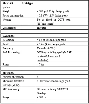
Table 1: Mode summary and system specifications of the MiniSAR prototype.
MiniSAR Prototype system
Weight < 50 kg (< 30 kg design goal)
Power consumption < 1.5 kW (1 kW design goal)
Volume To be fitted in COTS pod
(19”max length)
Data storage on-board
SAR mode
Resolution < 0.5 m (0.3m design goal)
Swath > 2 km (4 km design goal)
Frequency X-band (10 GHz)
SAR Processing Off-line, including spotlight SAR
mode (0.05 m azimuth resolution).
Range > 7 km
MTI mode
Number of channels 3
Minimum detectable < 10 km/h (5 km/u design goal)
velocity (MDV)
MTI Processing Off-line, including SAR/MTI
Overlays
© 2014, IJCSMC All Rights Reserved 545
5. CONCLUSIONS
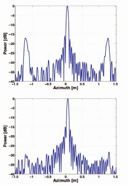
TNO-FEL has started the development of a prototype miniature SAR system called MiniSAR. Some of the key properties of the MiniSAR system. However, it is emphasized that the adaptive beam former fully dependent to the SNR of the input signal and calibration accuracy. Therefore an optimization strategy in practical system design will be studied in future work.
Designed for use in medium-altitude UAVs and manned platforms. State-of-the-art technology at X-band frequency.
Active Phased Array. Weight less than 50 kg.
Figure 6: Profile with 50% over-sampling ratio (upper) conventional orthogonal beam former and (lower) Capon’s beam former
Minimum Detectable Velocity (MDV) of 3 km/h with 0.5 km/h accuracy. SAR and MTI capability.
The ability to cue other sensors. Topographic maps with 1 m accuracy.
Height change (local deformation) maps with 1 cm accuracy. Image formation on-board with snap-shot processor.
© 2014, IJCSMC All Rights Reserved 546
REFERENCES
[1] I. G. Cumming and F. H. Wong, “Digital Processing of Synthetic Aperture Radar Data”, Norwood, MA, 2005.
[2] M. Soumekh, “Synthetic Aperture Radar Signal Processing with MATLAB Algorithms”, Wilet‐ Interscience, New York, 1999.
[3] Lu Hao , Cao Ning, Liu Weiwei, Wang Fei, Hu Jurong, “Efficient SAR Raw Data Simulation of Extended Scenes Using
Chirp Scaling Principle”, IEEE 2009, The 1st International Conference on Information Science and Engineering.
[4] A. Papoulis, “System and Transforms with Applications in Optics”, McGraw‐Hill, New York, 1968.
[5] R. Keith Raney, H. Runge, Richard Bamler, Ian G. Cumming, and Frank H. Wong, “Precision SAR Processing Using
Chirp Scaling”, IEEE Transactions on Geoscience and Remote Sensing, vol.32, no. 4, july 1994.
[6] Z. Li, H. Wang, and Z. Bao, “Generation of Wide-Swath and High-Resolution SAR Images from Multichannel Small
Space borne SAR System”, IEEE GRS Letters, Vol. 2, No. 1, pp. 82-86, Jan. 2005.
[7] M. Younis, C. Fischer, and W. Wiesbeck, “Digital Beam Forming in SAR System”, IEEE Transaction onGRS, Vol. 41, No. 71, pp. 1735-1739, Jul. 2003.
[8] N. Gebert, G. Krieger, and A. Moreira, “Digital Beam Forming for HRWS-SAR Imaging: System Design, Performance,
and Optimization Strategies”, IEEE Proceeding IGARSS, pp. 1836-1839, Jul. 2006.
[9] Holpp, Wolfgang, “The new generation of European E-scan fighter radars”, MTT-S International Symposium. IEE Conference Proceedings, 2010.
[10] Johannes van Bezouwen, Hanspeter Feldle, “Status and Trends in E-Scan Radar for Airand Spaceborne Applications”,
IMS Conference proceedings, 2010.


