Analysis of Attenuation Effect of Grid-Like Spatial Shields Used
in Lightning Protection of Buildings
Dino Lovri´c* and Slavko Vujevi´c
Abstract—A frequency-domain-based electromagnetic model of the lightning protection system of buildings is presented in this paper. Numerical model can accurately take into account all conductors of the lightning protection system, i.e., air-termination system, down-conductor system and earth-termination system. Using the presented electromagnetic model, attenuation effects of a grid-like spatial shield — sometimes used in lightning protection of buildings — will be analyzed for both the electric field and the magnetic field caused by a lightning strike. Three-dimensional distributions of the fields inside the shield are provided in the paper.
1. INTRODUCTION
Lightning protection system (LPS) of a building comprises an external LPS and an internal LPS. The purpose of the external LPS is to intercept direct lightning flashes via air-termination system conductors, conduct the lightning current from the interception point via the down-conductor system and safely disperse the lightning current into the surrounding soil via the earth-termination system. The purpose of the internal LPS is to prevent hazardous sparking inside the structure usually achieved by means of equipotential bonding. Sensitive equipment such as electrical and electronic systems inside the structure are protected on the principle of lightning protection zones, in which the building is divided into internal lightning protection zones according to the level of threat posed by the lightning electromagnetic pulse. Internal zones are in some cases, depending on the sensitivity and the cost of equipment, protected by spatial shielding. These spatial shields are in most cases grid-like shields in the form of steel reinforcements in the concrete and they provide a certain level of attenuation for the radiated lightning electromagnetic field. These attenuation effects will be addressed in this paper using an advanced numerical model of the LPS.
Numerical modelling of the LPS and computation of relevant electromagnetic quantities due to lightning strikes inside and around it has been a subject of interest for a number of researchers [1– 11]. These numerical models vary in many aspects — from the domain in which the computation is performed — time domain models such as [8, 9] or frequency domain models such as [11] to the general complexity with which the authors model the entire LPS and/or the medium in which it is situated (homogeneous ground or a more realistic and complex heterogeneous ground). A good numerical model should be able to produce results as accurately as possible in the least computation time possible taking important parameters such as ground stratification and electromagnetic coupling of LPS conductors.
In this paper, a frequency-domain-based transient electromagnetic model of the LPS is briefly described. This is in fact an expanded transient electromagnetic model of a grounding system published previously by the authors in papers [12–14, 17, 18]. An originally developed transformation procedure is employed [13, 14] instead of the ordinarily used FFT/IFFT. The transformation procedure
Received 20 February 2018, Accepted 13 May 2018, Scheduled 13 June 2018
* Corresponding author: Dino Lovri´c ([email protected]).
is characterized by mutually independent sampling in the time and frequency domains which enables faster computations while in fact improving the accuracy of results and eliminating errors which were sometimes present when using FFT/IFFT procedure [15]. The electromagnetic model of the LPS can take into account soil with an arbitrary number of layers, which are taken into account using the robust fixed image method developed in [16]. Formation and subsequent solving of ill-behaved Sommerfeld integrals is avoided by introducing an approximation in the form of an attenuation-phase shift factor [16]. This influence of this factor has been investigated in [17, 18] and it was concluded that the inaccuracies that it introduces into the model can be considered negligible but its influence on computational speed of the model is significant. Segments of external LPS conductors can be situated in any layer of the multilayer medium which includes air. The electromagnetic model can compute all electromagnetic properties of interest: scalar electric potential, vector magnetic potential, magnetic flux density and electric field intensity in any number of observation points situated in any layer. Using the presented model, authors will investigate the attenuation effect of grid-like metallic shields used in lightning protection of structures.
2. TRANSIENT ELECTROMAGNETIC MODEL OF THE LIGHTNING PROTECTION SYSTEM
Transient electromagnetic model of the lightning protection system presented in this paper is a frequency-domain-based model and as such has three main stages. Since the computation procedure is not performed directly in the time domain, but in the frequency domain, one firstly needs to transform the lightning current from the time domain into the frequency domain [19]. This is followed by the main computation which is performed over a limited set of frequency values. Finally, when the results are obtained for various frequency values, these results are transformed back to the time domain. In the following sections, a brief description of each of these steps used in the authors’ model will be provided.
2.1. Transformation of the Lightning Current into the Frequency Domain Using Continuous Numerical Fourier Transform
The presented transient electromagnetic model utilizes an originally developed continuous numerical Fourier transformation (CNFT) [13]. This transformation procedure nonuniformly samples the lightning current in the time domain using adaptive recursive sampling [20] to obtain the optimal number of sampled points. When a set of sampled points is obtained, then the lightning current is linearized over these sampled points using the finite element technique [21]. Linearization of the current enables the algorithm to analytically integrate the linearized lightning current into the frequency domain thus circumventing numerical integration of the oscillatory part of the Fourier integral. One additional advantage is that the resulting lightning current in the frequency domain is continuous which simplifies further computing since frequency samples can be chosen independently of the time domain samples. This is not the case when using standard Fast Fourier Transform algorithms [15]. CNFT algorithm can handle any mathematical approximation of the lightning current function and can even work with measured lightning current data. It is highly accurate and versatile as demonstrated in [13].
2.2. Frequency-Domain Computation of Electromagnetic Quantities
Although frequency-domain-based electromagnetic models have several advantages over models which compute in the time domain, they all have a common flaw — the computation procedure must be repeated for a relatively considerable number of frequencies. This is why the previously mentioned advantage of the CNFT algorithm is valuable, because it enables a more versatile frequency domain sampling procedure which can significantly reduce computation time since the selection of frequencies is not dependent on the time domain sampling.
and any grid-like metal shields inside the protected building. Using the presented model, one can compute all quantities of scientific and engineering interest in any number of observation points and in any point of the medium (air or ground). These quantities include scalar electric potential, vector magnetic potential, magnetic flux density and electric field intensity.
Each of the conductors is divided into segments to improve the accuracy of the average potential method which is a special case of the Galerkin-Bubnov method used in the electromagnetic model. The number of segments depends on the conductor length. Current of the conductor segments is divided into two dependent parts — the longitudinal current which flows along the conductor segment axis and the leakage current which leaks from the conductor segment surface into the surrounding medium. In the presented electromagnetic model, the longitudinal current of the segment is approximated linearly while the leakage current is, consequently, a constant along the segment length [12]. The effect of medium heterogeneity is taken into account using the robust and accurate fixed image method originally developed in [16]. Attenuation and phase shift effects of electromagnetic quantities in multilayered medium are taken into account using an approximate attenuation-phase shift factor [16–18], which circumvents the formation and subsequent solving of ill-behaved Sommerfeld integrals. The effect of using this factor on result accuracy has been investigated in [17, 18] where it was concluded that the loss of accuracy is not significant whereas the increase of computational speed which occurs when this factor is introduced is more than significant.
Initially, all conductor segments are disconnected in order to create a complete local system of equations which is formed using the Galerkin-Bubnov method. This is a linear system of equations for longitudinal and leakage segment currents which is transformed into an equivalent complete local system of linear equations for nodal currents [12]:
¯
Zt Z¯t
¯
Zb Z¯e
·nI¯=
⎡
⎣ 12 ·[E] 1 2·[E] [E] [E]
⎤
⎦·nΦ¯ (1)
whereZ¯tis a symmetrical transversal segment impedance matrix [17, 18]; Z¯b is a nonsymmetrical matrix of longitudinal impedances between segments and beginning nodes of segments [12]; Z¯eis a nonsymmetrical matrix of longitudinal impedances between segments and ending nodes of segments [12]; [E] is the unit matrix; nI¯is a vector representing local nodal currents;nΦ¯is a vector representing local nodal potentials. Elements of the symmetrical transversal segment impedance matrix Z¯t are computed analytically and have been derived in detail in [17, 18] whereas the nonsymmetric matrices ¯
Zeand Z¯eare computed numerically using an improved Gaussian quadrature [12].
The complete local system of equations for nodal currents can then be obtained from Eq. (1): ¯
Y·nΦ¯=nI¯ (2)
whereY¯represents the nodal admittance matrix of the local system which can be derived from Eq. (1). By equalizing the elements of the nodal current vector with zero, the incomplete local system of equations is obtained and is now ready for the assembly procedure:
¯
Y·nΦ¯={0} (3)
Using the assembly procedure, the previously disconnected segments become connected in global
nodes:
¯
Yg·Φ¯g=I¯g (4)
Scalar electric and vector magnetic potential in the observation point positioned within the i-th layer of the horizontally stratified multilayer medium can be obtained from the following expressions by summing the contributions of all segments of conductors (more detail in paper [18]):
¯ ϕi =
Ns
ks=1
¯
ϕksi (5)
Ai =
Ns
ks=1
¯
Aksi ·0ks (6)
whereksis the index number of the conductor segment, andNsis a total number of conductor segments. Here, ¯ϕksi and ¯Aksi are respective partial contributions of the arbitraryks-th segment to the scalar electric and vector magnetic potentials at the field point, while0ksis a unit vector of theks-th segment in
three-dimensional space. Electric field intensity at the field point, arbitrarily positioned within thei-th layer (including the layer boundary) of the multilayer medium, is obtained from the following expression [22]:
Ei=E¯ix,E¯iy,E¯iz=−∇ϕ¯i−j·ω·Ai = Ns ks=1 ¯ Eks i (7)
Magnetic flux density is computed directly from the vector magnetic potential using the following expression [22]:
Bksi =
¯
Bixks,B¯iyks,B¯izks
=∇ ×Aksi =
∇A¯ksi ×0ks (8)
A more detailed derivation of the presented expressions can be found in the authors’ previous work [22] where the harmonic electromagnetic model was derived initially.
2.3. Inverse Continuous Numerical Fourier Transform Frequency-Domain Computation of Electromagnetic Quantities
Transformation of the results is achieved using a similar algorithm to before — the inverse continuous numerical Fourier transform algorithm (ICNFT) originally developed in [14]. It is also based on nonuniform sampling in the frequency domain and linearization of the solution function over a frequency segment. This consequently enables analytical transformation of the linearized solution function back into the time domain. This algorithm has been extensively tested and its accuracy validated in [14].
3. ATTENUATION OF GRID-LIKE SPATIAL SHIELDS USED IN LIGHTNING PROTECTION OF STRUCTURES
Spatial shields are used in lightning protection of buildings to attenuate the effects of radiated electromagnetic field produced by lightning strikes and are primarily used for protection of building zones that contain particularly sensitive and/or expensive electronic equipment. These shields are most often in the form of grid-like meshed shields — Faraday cages — which also double as steel reinforcement in the concrete. The attenuation effect of the grid-like spatial shield is not identical for attenuation of electric and magnetic fields. As will be shown in the following examples, attenuation effects differ. It is well known that the attenuation of magnetic field is more difficult to achieve than the attenuation of the electric field especially for lower frequencies of the radiated field [23]. Usage of shielding materials with higher permeability values such as MuMetal [23] can improve the attenuation effects.
x (m) y (m)
z
(m)
Figure 1. Observed building and its external LPS.
following electrical properties: ρ1 = 100 Ωm, ρ2 = 500 Ωm, ρ3 = 1000 Ωm, εr1 =εr2 =εr3 = 10. The
thickness of the first two layers is 1 m and 2 m.
A couple of scenarios will be analyzed here involving two types of lightning strikes and the presence or absence of the grid-like spatial shield when protecting a zone in the building. In all cases, a 6×6×6 m zone positioned in the center of the building will be observed. Namely, electric and magnetic fields will be computed on a plane situated at a 1 m height in that zone for the shielded case and the unshielded case. In all cases the lightning strikes directly at the center point of the mesh situated on the top of the building. The parameters of each lightning strike are given in the following subsections.
3.1. First Scenario — First Positive Impulse
In the first case scenario, the building external LPS is assumed to be struck by a first positive impulse which has relatively slower rise-time and decay-time and is characterized by larger amplitudes of the lighting current. This impulse is modelled by the Heidler function [24] with the following function parameters: I0 = 100 kA, η= 0.93, τ1 = 19µs, τ2= 485µs andn= 10. Four cases in this scenario are
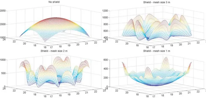
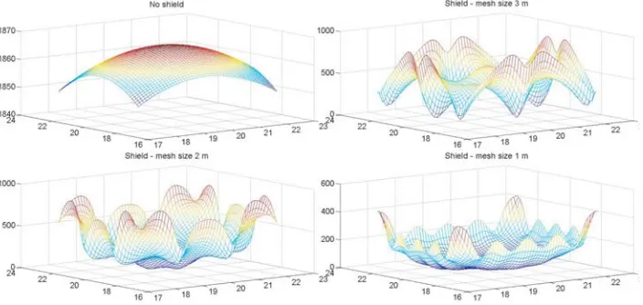
analyzed: a) the zone is unshielded, b) zone shielded by a grid-like spatial shield of mesh size 1 m, c) zone shielded by a grid-like spatial shield of mesh size 2 m, and d) zone shielded by a grid-like spatial shield of mesh size 3 m. As mentioned before, three-dimensional computation of electric field intensity
Figure 3. Three-dimensional depiction of the total electric field intensity for the first positive stroke at t= 50µs.
Figure 4. Three-dimensional depiction of the total electric field intensity for the first positive stroke at t= 100µs.
Figure 6. Three-dimensional depiction of the total magnetic flux density for the first positive stroke at t= 50µs.
Figure 7. Three-dimensional depiction of the total magnetic flux density for the first positive stroke at t= 100µs.
and magnetic flux density is performed on the observation plane situated at a 1 m height from the lowest point of the zone. The observation plane consists of 2601 observation points in which the fields are computed.
Figures 2–4 depict the three-dimensional distribution of the total electric field intensity on the observation plane at 20µs, 50µs and 100µs. Figures 5–7 depict the three-dimensional distribution of the magnetic flux density on the same observation plane at 20µs, 50µs and 100µs. It can be noted from these figures that the attenuation effect is in fact drastically more evident in the case of electric field than in the case of the magnetic field which was to be expected due to reasons mentioned previously. Furthermore, one can also notice the increase in attenuation effects for a denser mesh of conductors in the shield.
3.2. Second Scenario — First Negative Impulse
In the second case scenario, the building external LPS is assumed to be struck by a first negative impulse which has faster rise-time and decay-time. This impulse is also modelled by the Heidler function with the following function parameters: I0= 100 kA, η= 0.986, τ1 = 1.82µs,τ2= 285µs andn= 10. As in
Figure 8. Three-dimensional depiction of the total electric field intensity for the first negative stroke at t= 20µs.
Figure 9. Three-dimensional depiction of the total electric field intensity for the first negative stroke at t= 50µs.
Figure 11. Three-dimensional depiction of the total magnetic flux density for the first negative stroke at t= 20µs.
Figure 12. Three-dimensional depiction of the total magnetic flux density for the first negative stroke at t= 50µs.
Figure 14. Three-dimensional depiction of the total electric field intensity for the subsequent negative stroke att= 20µs.
Figure 15. Three-dimensional depiction of the total electric field intensity for the subsequent negative stroke att= 50µs.
of the total electric field intensity on the observation plane at 20µs, 50µs and 100µs. Figures 11–13 depict the three-dimensional distribution of the magnetic flux density on the same observation plane at 20µs, 50µs and 100µs. Again, it can be noted from these figures that the attenuation effect is more evident in the case of electric field than in the case of the magnetic field. Furthermore, one can also observe the increase in attenuation effects for a denser shield mesh which is evident both in the electric field case and the magnetic field case which is also to be expected.
3.3. Third Scenario — Subsequent Negative Impulse
In the third case scenario, the building external LPS is assumed to be struck by a subsequent negative impulse which has the fastest rise-time and decay-time. This impulse is also modelled by the Heidler function with the following function parameters: I0 = 50 kA, η = 0.993, τ1 = 0.454µs, τ2 = 143µs
and n = 10. As in the previous scenario, four cases are analyzed. Figures 14–16 depict the three-dimensional distribution of the total electric field intensity on the observation plane at 20µs, 50µs and 100µs. Figures 17–19 depict the three-dimensional distribution of the magnetic flux density on the same observation plane at 20µs, 50µs and 100µs.
Figure 17. Three-dimensional depiction of the total magnetic flux density for the subsequent negative stroke att= 20µs.
Figure 19. Three-dimensional depiction of the total magnetic flux density for the subsequent negative stroke att= 100µs.
4. CONCLUSION
In this paper, a frequency-domain-based transient electromagnetic model of the lightning protection system is briefly described. Transformation between time and frequency domains is solved using forward and inverse continuous numerical Fourier transforms developed in the authors’ previous work. Using the proposed model, it is possible to compute all electromagnetic quantities of scientific and engineering interest in any observation point. This paper briefly analyzes the attenuation effect of grid-like spatial shields used in lightning protection of buildings. The analysis is performed for both the electric field and the magnetic field. It is demonstrated that the magnetic field is much harder to attenuate as expected from the electric field.
REFERENCES
1. Sowa, A., “Lightning overvoltages in wires within the buildings,” International Symposium on Electromagnetic Compatibility, 99–102, 1991, DOI: 10.1109/ISEMC.1991.148192.
2. Sowa, A., “Surge current distribution in building during a direct lightning stroke,” International Symposium on Electromagnetic Compatibility, 12–16, 1991, DOI: 10.1109/ISEMC.1991.148193. 3. Li, L. and V. A. Rakov, “Distribution of currents in the lightning protective system of a residential
building — Part II: Numerical modeling,” IEEE Transactions on Power Delivery, Vol. 23, No. 4, 2447–2455, 2008.
4. Hedge, V. and V. Shivanand, “On the characteristics of lightning currents in the steel reinforced concrete building due to a lightning strike,”Asia-Pacific Symposium on Electromagnetic
Compatibility (APEMC), 865–868, 2012, DOI: 10.1109/APEMC.2012.6237924.
5. Markowska, R., “Lightning current distributions in LPS of a building with a radio base station on the roof,”2009 International Symposium on Electromagnetic Compatibility Kyoto, 845–847, 2009. 6. Miyazaki, S. and M. Ishii, “Role of steel frames of buildings for mitigation of lightning-induced magnetic fields,” IEEE Transactions on Electromagnetic Compatibility, Vol. 50, No. 2, 333–339, 2008.
7. Ishii, M., K. Miyabe, and A. Tatematsu, “Induced voltages and currents on electrical wirings in building directly hit by lightning,” Electric Power Systems Research, Vol. 85, 2–6, 2012.
9. Tatematsu, A., F. Rachidi, and M. Rubinstein, “Calculation of electromagnetic fields inside a building with layered reinforcing bar struck by lightning using the FDTD method,” International Symposium on Electromagnetic Compatibility, 386–389, 2014.
10. Liu, R., Y. Wang, Z. Zhao, and Y. Zhang, “Magnetic field distribution inside metallic grid-like buildings struck by lightning based on finite element method,” International Conference on Lightning Protection, 1712–1715, 2014.
11. G´omez, P., “Frequency domain model for transient analysis of lightning protection systems of buildings,”Heliyon, Vol. 2, 1–19, 2016.
12. Lovri´c, D. and S. Vujevi´c, “Fixed-image-method-based transient electromagnetic model of grounding system in horizontally stratified multilayer medium,” Progress In Electromagnetics Research M, Vol. 44, 1–12, 2015.
13. Vujevi´c, S. and D. Lovri´c, “On continuous numerical Fourier transform for transient analysis of lightning current related phenomena,”Electric Power Systems Research, Vol. 119, 364–369, 2015. 14. Vujevi´c, S. and D. Lovri´c, “Inverse continuous numerical Fourier transform for transient analysis of
electromagnetic phenomena,”IEEE Transactions on Electromagnetic Compatibility, Vol. 57, No. 5, 1149–1154, 2015.
15. Chu, E. and A. George, Inside the FFT Black Box, Serial and Parallel Fast Fourier Transform Algorithms, CRC Press, Boca Raton, 2000.
16. Vujevi´c, S. and P. Sarajˇcev, “Potential distribution for a harmonic current point source in horizontally stratified multilayer medium,” COMPEL — The International Journal for Computation and Mathematics in Electrical and Electronic Engineering, Vol. 27, No. 3, 624–637, 2008.
17. Sarajˇcev, P., S. Vujevi´c, and D. Lovri´c, “Time-harmonic current distribution on conductor grid in horizontally stratified multilayer medium,” Progress In Electromagnetics Research B, Vol. 31, 67–87, 2011.
18. Vujevi´c, S., P. Sarajˇcev, and D. Lovri´c, “Time-harmonic analysis of grounding system in horizontally stratified multilayer medium,”Electric Power Systems Research, Vol. 83, No. 1, 28–34, 2012.
19. Beerends, R. J., H. G. Ter Morche, J. C. van den Berg, and E. M. van de Vrie,Fourier and Laplace Transforms, Cambridge University Press, Cambridge, 2003.
20. Gander, W. and W. Gautschi, “Adaptive quadrature — Revisited,” BIT, Vol. 40, No. 1, 84–101, 2000.
21. Silvester, P. P. and R. L. Ferrari,Finite Elements for Electrical Engineers, 3rd Edition, Cambridge University Press, Cambridge, 1996.
22. Sarajˇcev, P., S. Vujevi´c, and D. Lovri´c, “Computing the electromagnetic field of the system of arbitrarily positioned conductors in horizontally stratified multilayer medium,” International Journal of Numerical Modelling — Electronic Networks Devices and Fields, Vol. 28, No. 2, 121– 137, 2015.
23. Paul, C. R., Introduction to Electromagnetic Compatibility, Wiley India Private Limited, 2010. 24. Heidler, F., “Analytical lightning current function for LEMP-calculation,”International Conference