IJEDR1403028
International Journal of Engineering Development and Research (www.ijedr.org)3066
A Model Based Approach for Algorithm
Development in Real Time Operation of Automated
Guided Vehicle Using Labview
Anjay Prasad, Vishal Prakash Halale, Siddhant Vinod Bora
Students, School of Mechanical and Building Sciences, VIT University, Vellore-632014, Tamilnadu, India
________________________________________________________________________________________________________
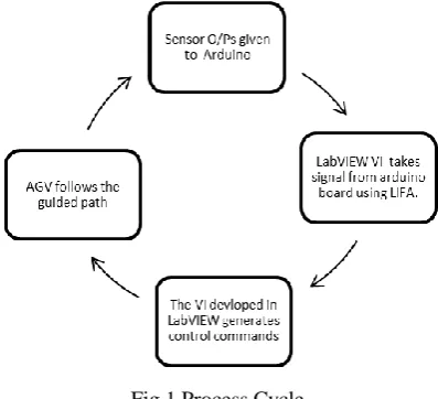
Abstract - In recent Automated Guided Vehicles (AGV) are emerging as useful technology assisting manufacturing and production in industries. These vehicles are used as advanced technology to help in the process of industrial automation. There are various methods of path planning of AGV like; Grid-based map methods, Potential field techniques, Fuzzy logic control, and Neural network algorithms. In this paper we are applying Grid based mapping with the help of AVR microcontroller kit, collision avoidance sensor, path following sensors, all integrated with LabVIEW for controlling and feedback operation. The objective of this paper is to design a prototype using Arduino board and LabVIEW software that will provide exact location and condition of AGV. Here we are developing an inexpensive, mobile and intelligent AGV prototype that will be interfaced with LabVIEW by use of toolkit named ‘LabVIEW interface for Arduino’ (LIFA) and Arduino-Uno board. The LabVIEW according to the sensor information given to the Arduino board gives commands for controlling the operation of the AGV. The communication between Arduino board situated on AGV and LabVIEW is achieved wirelessly by ZigBee module.
Keywords - Automated Guided Vehicle (AGV), Arduino, ZigBee Module, LabVIEW, LIFA
________________________________________________________________________________________________________ I. INTRODUCTION
Automated Guided Vehicles (AGV) have been applied for the flexible manufacturing system. Many factories adopted it into assembly line or production line such as automobile, food processing, wood working, and other factories. Many researchers developed and designed it in order to suite with their applications which are related to the main problem of factory. AGV works on a predefined guidelines. Steering control of mobile robot is done using controller based on predefined path data. The various ways for defining the path include optical, magnetic, laser guided, GPS control etc. Our objective here is to develop a prototype of an AGV using Arduino-Uno controller board and virtual instrument environment software LabVIEW.
Fig 1 Process Cycle
1.1. Design of system
IJEDR1403028
International Journal of Engineering Development and Research (www.ijedr.org)3067
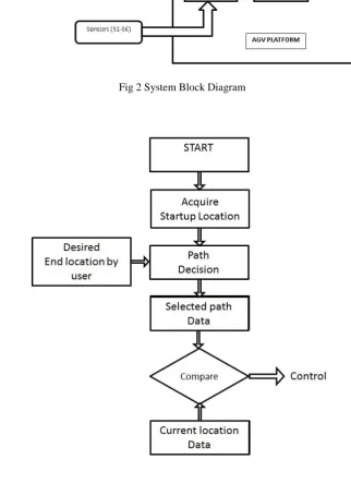
1.2. Software DesignFig 3 Flow chart As shown in figure 3 the software program will perform following tasks:
IJEDR1403028
International Journal of Engineering Development and Research (www.ijedr.org)3068
Fig 4 (a) Current position detector block (b) Sensor output table Path decision block: After getting current and final position information the path decision block will decide the shortest path between the two points using shortest path algorithm. It is shown in figure 5 below. Note here X is the crossover point in the path.
Fig 5 (a) Path decision block (b) Path selection table
AGV control block: Now according the path no. a subVI will continuously monitor line sensors (S1 & S2) and control the motors to guide the platform on predefined path. The LabVIEW Interface for Arduino will be used to interface its digital input and output pins with software.
Fig 6 Line Follower Block II. CONTROL SYSTEM DESIGN
2.1. Sensor Selection
Conventionally different types of sensors are used in the design process of AGV: - IR Transmitter and receiver pair - Used for detecting specific pattern. - Inductive proximity sensor - Used to detect metal surface pattern.
In our work we are using 6 pairs of IR transmitter and receiver at various locations in robot. Here the pairs are matched for fine tuning of both the sensor in proximity. The pair is similar to White Line or Micro mouse sensor. It consists of 5mm 940 nanometer wave length high power IR LED and photodiode having peak sensitivity at 940 nanometer wavelength.
Some important and useful characteristics of IR Transmitter receiver are: - IR TX RX size: 5mm diameter package
IJEDR1403028
International Journal of Engineering Development and Research (www.ijedr.org)3069
Fig 7 Circuit Diagram of IR Transmitter and Receiver III. CONTROLLER CIRCUITRY
3.1. Arduino
Arduino modules are mostly used for educational purpose and components are very affordable. Arduino modules can run on different platform and the overall system can easily run on different operating system. It‟s Hardware and software is open source i.e. it has public access and anyone can use it, edit it for improvement.
In our work we use various sensors like IR sensor, Infrared obstacle detection sensor. The sensor data is gathered using Arduino microcontroller, control action like DC motor control can also be done simultaneously by Pulse Width Modulation (PWM) using Lab View-Arduino interface with the physical world.
As shown in the figure below the Arduino board comes with 28 I/O pins, which are mounted on Arduino board giving us 13 digital I/O pins and 5 Analog input pins.
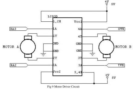
Fig 8 Arduino Board 3.2. Motor Driver Circuitry
IJEDR1403028
International Journal of Engineering Development and Research (www.ijedr.org)3070
Fig 9 Motor Driver Circuit3.3. LabVIEW interface for Arduino (LIFA)
National Instruments‟ LabVIEW toolkit helps us to easily interface LabVIEW software with Arduino microcontroller. Using toolkit and LabVIEW, one can control or acquire data from the Arduino microcontroller. Once the information is in LabVIEW, LabVIEW analyzes it using hundreds of built-in libraries, developing algorithms to control the Arduino hardware, and presenting the findings on a polished User Interface (UI). A sketch for the Arduino microcontroller acts as an I/O engine that interfaces with LabVIEW VI‟s through a serial connection. This helps you to quickly move information to and fro between Arduino pins and LabVIEW without adjusting the communication and synchronization. By the built in control functions in LIFA like Read/Write, Close you can access the digital, analog, pulse-width-modulated, I2C and SPI signals of the Arduino microcontroller.
3.4. Signal manipulation using Arduino
Arduino boards are like small computer boards having a defined number of input and output pins. We can write program through pins and send data serially using Universal Serial Bus (USB) of computer. The control operation begins by writing commands in LabVIEW. As discussed before here we are making the connection with Arduino using LabVIEW Interface for Arduino toolkit (LIFA), the toolkit provides a wide variety of flexibility in writing the codes with the help of various libraries like programming, express, VISA control etc. The advantage of using LabVIEW is that it provides a clean and neat graphical user interface (GUI) and provides east step by step debugging before actual use of the program. Thus we can confirm the perfect required output from LabVIEW to external hardware. The sensors connected on the prototype robot will sense the outside world and give output to the microcontroller. The steering control of the robot is done in LabVIEW case statement with the sensor output. A sketch is developed using Arduino IDE for the microcontroller so that it can act as a medium between the outside world and the software. The communication between the hardware and software is done wirelessly using ZigBee module. This process is repeated as long as the mobile robot reaches the required destination station.
IJEDR1403028
International Journal of Engineering Development and Research (www.ijedr.org)3071
Fig 11 Map of Guided PathThe guided path map consists of three stations (A, B and C). There are six paths numbered from 1-6 which formed by interconnecting the three stations. There are crossovers at certain points (indicated by X)in the path where the AGV will turn by approximately 90 degree to go from one station to other station skipping the middle station in between these two stations. E.g. In case we want to go from station A to station C directly bypassing the station B, the AGV commands will be like this, First the AGV will start from station A following the path 1, in the middle as it wanted to go to station B it will deviate from path 1 to path 3 to go to station C through intermediate path 2. For finding out which path it should take, a crossover „X‟ is used as the reference point on the map. Thus the AGV will achieve motion from Station A to Station C skipping the Station B between.
For seeing the results we observed when the AGV was going from station C to station A, we changed the destination station to B by modifying the value in LabVIEW VI. The AGV which was following the path 4 now got to know that it has to go to path 1 to reach the station B; it started to scan for a crossover point. When the AGV got the location of the crossover point it turned approximately by 90 degrees and moved to path 1 through traversing the path 5. Thus the other stations can be traversed by using the path selection table as shown in Figure (5.b)
V. ADVANTAGES OF USING LABVIEW
- The code can be compiled to generate distributable EXEs.
- Flexible, powerful and scalable design (can open and connect to third party tools along with external libraries). - Easy to Learn, maintain, use and upgrade (using graphical constructs and intuitive graphical programming). - Use of one tool for design, prototyping and deployment.
- Can be used in Multidisciplinary fields (easy VI programming language for different applications and expert use in different disciplines of science and engineering).
- Good hardware- software integration (supports wide range of data acquisition and embedded devices). - Multiplatform (Mac OS, Linux, Windows, RTOSs etc.)
- Easy communication with instruments using serial, Bluetooth or wireless communication. - Real time solving and execution of complex algorithms.
- Acts as the Bridge to industry – nowadays many industries are using LabVIEW as the control system software for controlling various processes in the plant.
- Help to develop better and faster algorithms.
- Shorter time to prototype, discovery and deployment to market. VI. CONCLUSION
IJEDR1403028
International Journal of Engineering Development and Research (www.ijedr.org)3072
REFERENCES[1] Sudha Arora, A.K.Rain, A.K.Mittal, “Hybrid Control in Automated Guided Vehicle Systems”, 2001 IEEE Intelligent Transportation Systems Conference Proceedings - Oakland (CA), USA - August 25-29, 2001.
[2] Lothar Schulze, Alexander Wtillner,“The Approach of Automated Guided Vehicle Systems”, Service Operations and Logistics, and Informatics, 2006. SOLI‟06. IEEE International Conference on Digital Object Identifier: 10.1109/SOLI.2006.328941 Publication Year: 2006, Page(s): 522 – 527.
[3] Ryan G. Rosandich, Richard R. Lindeke, Jeff Berg, “DEVELOPING AN AUTOMATIC GUIDED VEHICLE FOR SMALL TO MEDIUM SIZED ENTERPRISES”, May 2007.
[4] Robert H. Bishop, “Learning with LabVIEW Express”, Prentice Hall Publication, Fourth Edition, January 2008.
[5] Mohd Azlan Shah Abd Rahim, Illani Mohd Nawi, “Path Planning Automated Guided Robot”, Proceedings of the World Congress on Engineering and Computer Science 2008, San Francisco, USA, WCECS 2008, October 22 - 24, 2008. [6] Maik Schmidt, “Arduino, a quick start guide”, The Pragmatic Programmers.