R E S E A R C H
Open Access
Energy-efficient and reliable wireless sensor
networks - an extension to IEEE 802.15.4e
Achim Berger
1*, Markus Pichler
1, Werner Haselmayr
2and Andreas Springer
2Abstract
Collecting sensor data in industrial environments from up to some tenth of battery-powered sensor nodes with sampling rates up to 100 Hz requires energy-aware protocols, which avoid collisions and long listening phases. The IEEE 802.15.4 standard focuses on energy-aware wireless sensor networks (WSNs) and the Task Group 4e has published an amendment to fulfill up to 100 sensor value transmissions per second per sensor node (low latency deterministic network (LLDN) mode) to satisfy demands of factory automation. To improve the reliability of the data collection in the star topology of the LLDN mode, we propose a relay strategy, which can be performed within the LLDN schedule. Furthermore, we propose an extension of the star topology to collect data from two-hop sensor nodes. The proposed retransmission mode enables power savings in the sensor node of more than 33%, while reducing the packet loss by up to 40%. To reach this performance, an optimum spatial distribution is necessary, which is discussed in detail.
Keywords: Wireless sensor networks (WSNs); TDMA; Energy-efficient protocol; Real-time protocol; IEEE 802.15.4e
1 Introduction
The technological progress in wireless microelectronics offers the usage of battery-powered sensor nodes with acceptable battery lifetimes in many areas from consumer electronics to industrial applications [1]. Miniaturized, battery powered, and self-sufficient sensor nodes are sens-ing physical properties and the wireless sensor network (WSN) is responsible for transmitting the sensed data to a base station for further processing. Wireless data communication allows exposed sensor positions, e.g. at rotating or moving machine parts, which are not reach-able by wired bus systems or creach-ables for mains powering. The requirements on the data traffic can be very diverse from real-time, reliability, scalability, deterministic behav-ior, to low-power. Each application has its individual set of requirements.
In our work, we focus on WSNs for real-time data col-lection from battery or energy harvester-powered minia-turized sensor nodes [2] to mains powered data sinks with transmission of up to 100 sensor values per second and high reliability. The data sink (later called coordi-nator and the gateway to a wired industrial network) is
*Correspondence: [email protected]
1Linz Center of Mechatronics GmbH, Altenbergerstr. 69, Linz 4040, Austria Full list of author information is available at the end of the article
stationary, while the sensor nodes (later called device) are distributed over an industrial plant. Most of the devices are stationary, but might also be mobile. The time vary-ing wireless channels between the nodes and the gateway are characterized by multipath propagation due to large-scale reflectors, moving and stationary obstacles, LOS and non-LOS links, and different interferers. The limited power resources in the sensor nodes require a balance between energy awareness and retransmission attempts. The first aim of this work is an improvement of the relia-bility while saving energy in the sensor nodes. Therefore, we introduce a (wherever applicable mains powered) relay node which supports the sensor nodes in saving energy and increasing data transmission reliability by performing retransmissions.
We decided to use the most widely adopted standard for low-rate WSN and wireless personal area networks (WPANs), IEEE 802.15.4 [3], which is optimized for energy efficiency, low-cost implementation, and low data rate traffic. The standardized Physical Layer (PHY) is already available in a variety of transceivers from dif-ferent semiconductor companies [4,5]. Two competing protocols, which use the IEEE 802.15.4 PHY, are the wireless version of the fieldbus HART, WirelessHART, and the ISA100.11a standard. Petersen and Carlsen [6] described the basics of these two protocols and discussed
the pro and cons of both systems. The evaluation in [7] shows a significant portion of energy consumption due to (over)listening, which can be seen as wasted energy. An improvement of the IEEE 802.15.4 Medium Access Layer (MAC) by optimized scheduling is shown in [8].
The IEEE 802.15 Task Group 4e (TG4e) was intended to amend IEEE 802.15.4 to better support the industrial mar-kets and permit compatibility with modifications being proposed within the Chinese WPAN [9]. The amendment of TG4e offers new MAC-layer possibilities which are optimized amongst others for factory automation. In fac-tory automation, usually many sensor and actuator nodes (e.g. up to 100) are connected in star topology requiring deterministic data transmission at low latency and high reliability [10,11].
Low latency deterministic networks (LLDN) is a spec-ified mode in the IEEE 802.15.4e Amendment of the IEEE 802.15.4 WPAN Standard which is designed for deterministic applications in industrial environments, where frequency planning should achieve minimal inter-ference from other RF systems. The focused applications range from monitoring purposes with short delays to closed loop control with sampling rates up to 100 Hz. The main benefit of the LLDN mode is the possibility of peri-odically transmitting sensor data from an (typically bat-tery powered) ‘LLDN device’ to the ‘LLDN coordinator’ in 10 ms cycles, which has not been possible in a beacon-enabled mode of the IEEE 802.15.4 standard. Another very important feature of the IEEE 802.15.4e standard are the provided time slots for retransmission, which are funda-mental for our proposed transmission modes. However, the high data throughput with the reserved resources for retransmissions reduces the number of sensor nodes per network. Our first approach is a retransmission mode which saves energy in the device by using a new relay node. In case of bad link quality between device and coordinator, characterized by a high packet error rate (PER), this mode is more beneficial in terms of reliability and energy consumption compared to the retransmission strategy of the LLDN mode. But the benefits can only be achieved if the position of the relay is optimized. Tripathi et al. describe a similar position optimization for a base station, where individual adjustable transmission powers are assumed [12].
Our second proposal in this work targets the expansion of the coverage area by relay nodes. The network topol-ogy in the LLDN mode is limited to a star topoltopol-ogy by definition and the covered area is restricted to a maxi-mum diameter of two times the communication range. To expand the area of the WSN, data must be forwarded from devices outside the communication range of the base sta-tion via a relay node. We propose a way to extend the star topology to an extended star topology, so that the coor-dinator can collect data from so-called two-hop devices
in a deterministic way, within the same superframe. A typical way of connecting two-hop nodes to a coordina-tor are relay strategies [13] or routing techniques in a tree, clustered tree [14] or mesh network topology, which usually uses more time and energy due to the required organization of the network [15].
The second proposal of this work is forwarding data from a device out of communication range to the coor-dinator in real-time by a second type of relay node. Our understanding of real-time is to have the sensor data avail-able at the coordinator in the same superframe, in which they are generated, i.e. in 10 ms periods. All proposed modifications can be performed in the standard conform LLDN mode or with just minor modifications.
The paper is organized as follows: Existing standards and relevant publications are discussed in section 2. Section 3 introduces the LLDN mode with its standard conform retransmission strategy. Our proposals are pre-sented in sections 4 and 5. The comparison and the quan-tification of the improvement are discussed in section 6 and concluded in section 7.
2 Related work
WirelessHART is an already established protocol for wireless industrial sensing applications. The schedule of WirelessHART is based on the Time Synchronized Mesh Protocol (TSMP, [16]), which enables very flexi-ble, reliaflexi-ble, and scalable wireless mesh networks. This protocol was further developed in the Time Synchro-nized Channel Hopping (TSCH), which is part of the IEEE 802.15.4e Amendment and improved by different scheduling and synchronization algorithms [17]. The tim-ing is organized in time slots, which are collected to so-called slotframes. A TSCH time slot typically allows one data frame transmission with the corresponding acknowl-edgment frame. Therefore, a single slot has to be long enough to accommodate reception of the clear channel assessment (CCA), if enabled, followed by the switch to transmission, packet transmission itself, switch to recep-tion, and finally acknowledgment receprecep-tion, if enabled. Thus, WirelessHART and most other protocols based on TSCH or TSMP use a time slot duration of 10 ms and so it is not applicable to perform up to 100 transmissions of sensor values per second from up to some tenth of sensor nodes.
cooperative communication and the proper selection of up to two relay nodes is done in [20]. Laneman et al. [21] show the benefits of cooperative schemes against the adverse effect of channel fading. Srinivasan et al. [22,23] presented wireless link indicators to evaluate the performance of routing and network coding protocols. Their so-called κ factor indicates the inter-link recep-tion correlarecep-tion, while theβ factor describes the bursti-ness disturbance of the wireless channel. LLDN mode is assumed to be operated in a controlled RF environ-ment [9]; thus, the transmission errors are mainly caused by multipath propagation, which results in a κ factor around zero, which means independent receptions in uplink and downlink, even if the probability of error is the same in both links due to the reciprocity of multipath propagation.
3 LLDN Mode of 802.15.4e
3.1 General
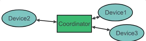
The LLDN mode of IEEE 802.15.4 uses three states, the ‘Discovery State’, the ‘Configuration State’, and the ‘Online State’. After powering up the nodes of the net-work, they are in the ‘Discovery State’, where the coordi-nator scans the environment for applicants to the network and waits for their response. After finishing the ‘Discovery State’ the network nodes enter the ‘Configuration State’, where the setup of the network is performed. The rel-evant state for data transfer is the ‘Online State’, where data packet transmissions are executed in a Time Division Multiple Access (TDMA) schedule for a star network topology (Figure 1).
The TDMA schedule in the ‘Online State’ is organized in superframes, which are divided into a slot for a bea-con, optionally time slots for management, and time slots of equal length for data transfer. The versatile config-uration possibilities allow to setup a time slot as dedi-cated to one device or assigned to a group of devices, the communication in the slot as unidirectional or bidi-rectional, and as acknowledged or not [9]. The LLDN superframe contains also retransmission time slots, which offer low latency retransmission attempts in the same superframe, which are the basis for our two propos-als. The high degree of flexibility of the LLDN mode can also be seen in the user-defined fragmentation of
Figure 1Star network.Example of the spatial distribution in the star network topology considered in the IEEE 802.15.4e standard.
downlink, uplink, and retransmission slots, as shown in Figure 2.
The slot configuration we want to consider in the following modes uses the feature of a separate Group Acknowledgement frame (GACK) in a dedicated uplink time slot while no management and no bidirectional time slots are used. The GACK frame includes the bit-mapped acknowledgement information, one bit for each time slot.
3.2 Standard-conform retransmission
The Standard Mode (‘SM’) considers a network topol-ogy as shown in Figure 1 and a schedule shown in Figure 3, which represents one LLDN configuration exam-ple of IEEE 802.15.4e, where n is the total number of time slots (beacon slot excluded, GACK slot included) and r the number of retransmit slots. A 10 ms super-frame provides eight regular and eight retransmission slots, one pair for each node, with a 2-byte payload
(n = 17 and r = 8). The coordinator is the
gate-way and is mains powered, while the devices are bat-tery powered and in the communication range to the coordinator.
The exemplary schedule in Figure 3 shows a success-ful first transmission from device1 to the coordinator, while the first attempt of device2 is not successful. In this work, we distinguish between ‘good’ and ‘bad’ links, which represent wireless links with low and high PER without quantifying them. The reasons for different link qualities range from path loss to static and dynamic mul-tipath propagation [24,25] to fast moving or rotating sensor nodes [26,27]. For the calculations regarding spa-tial distribution of link qualities in section 6, we will use large-scale propagation models, which characterize sig-nal strength over transmission distances from 2 to 100 m [28]. This is a simplification compared to a realistic fac-tory environment [29], but allows to derive closed-form results.
Due to the information transmitted in the GACK frame, device2 receives permission to transmit its packet in the first retransmission time slotSr1 again. The device’s transceiver activities in one superframe in case of a suc-cessful transmission are one transmission and two recep-tions. Device2, which requires a second transmission, needs two transmissions and two receptions.
Figure 2LLDN mode superframe.Superframe in the LLDN mode of the IEEE 802.15.4e standard with separate Group Acknowledgement frame [9].
is not received by the device and thus a retransmission is initiated)
PSM,Retr=PERC2D+PERD2C−PERC2DPERD2C, (1)
if we assume the packet errors in uplink and downlink to be independent. Thus, the energy consumption due trans-mission and reception in the devices in one superframe results in
ESM,Device=(1+PSM,Retr)ETX,Data+ERX,Beacon+ERX,GACK, (2)
whereETX,Data,ERX,BeaconandERX,GACKare the consumed energy per transmission and reception of data packet, beacon and group acknowledgment.
A second important parameter is the probability of loosing data packets, i.e. packets which are not received successfully by the coordinator, which are evaluated by the packet loss rate (PLR). Compared to the PER, where each lost packet between transmitter and receiver is con-sidered, the PLR is the probability of loosing data after the retransmission attempt(s).
The data packet transmission in SM is successful, when either the first transmission attempt (with probability
1 − PERD2C) or the retransmission is received by the coordinator (with probability PERD2C(1−PERD2C)):
PLRSM=1−[(1−PERD2C)+PERD2C(1−PERD2C)]
=PER2D2C. (3)
4 Retransmission mode
To improve the reliability of the data packet transmission while staying compatible with the standard, we propose the introduction of a novel retransmission mode (RM) which uses a relay node.
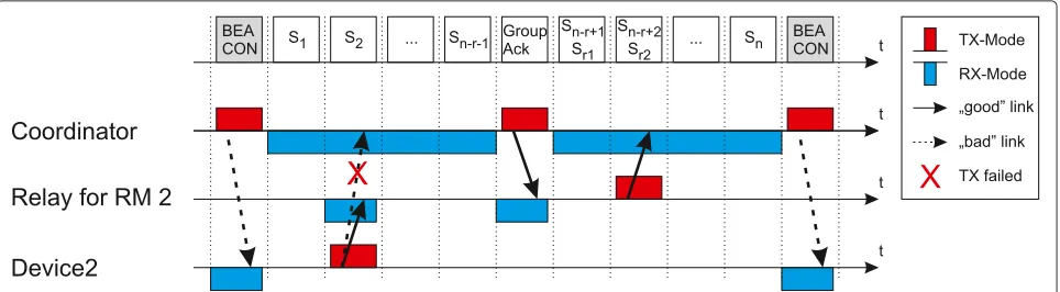
Figure 4 shows an example for a spatial distribution which can use the novel RM. In this configuration, the LLDN device (e.g. device2 in Figure 4) operates as a sen-sor node without ACK demand and has a direct wireless link to the coordinator, probably with low reliability, i.e. high PER (‘bad’ link). To improve the reliability of this link, we introduce a new type of node, the ‘relay for RM’ node, which is stationary and mains powered. Relay_for_RM_2 in Figure 4 is such a node, which can communicate with device2 and the coordinator. To have the coordinator and the assigned device in its transmission range is a mandatory requirement for the relay for RM node.
The task of the relay_for_RM_2 node, as shown in the schedule in Figure 5, is to listen for data packets, which
Figure 4Connection with relay node for RM.Example of the spatial distribution in the star network of the IEEE 802.15.4e standard with the additional relay node for RM. (Solid arrow represents ‘good’ link; dashed arrow represents ‘bad’ link).
are sent from device2 to the coordinator and retrans-mit it in case of a negative acknowledgement. Therefore, it has to operate in receiving mode during the regular packet transmission and the GACK transmission, and to transmit a data packet if needed. If the device is config-ured without ACK demand, it does not listen for GACK and thus would not disturb the retransmission attempt of the relay. So there is no need of adaptations in the device’s software. In the example shown in Figure 5, the first transmission attempt of the data packet fails and the relay for RM retransmits the data packet because it received the packet successfully and knew about the failed attempt of device2 due the GACK information. Device2 has to perform only one transmission (regular transmission in the assigned time slot) and one reception (for the beacon).
The proposed relay for RM node is capable to sup-port the retransmission for a few devices and thus should be placed (if possible) where it can establish the best connection to all associated nodes. In most applications, it is predetermined where the sensor nodes have to be placed, e.g. where temperatures or accelerations have to be measured from moving or rotating machine parts. So only the positions of the relay nodes are subject to optimiza-tion. Optimization criteria are minimizing loss of data packets and energy consumption in the devicea.
The computation of the energy consumption has to be performed for the device and the relay. Like in SM, the energy consumption is a function of the link quality. The relay for RM node assumes the need for a retransmission if either the packet transmission from the device to the coor-dinator or the GACK transmission from the coorcoor-dinator to the relay failed. Furthermore, to enable a retransmis-sion, it is necessary that the relay node receives the data packet from the device successfully. The probability that a retransmission of the relay to the coordinator is neces-sary, assuming that the retransmission slot is assigned and knowna priori, is
PRM,Retr=(1−PERD2R) (PERD2C+PERC2R
− PERD2CPERC2R).
(4)
The energy consumption of a single device per super-frame is constant, because it always results from only the reception of one beacon and transmission of one data packet:
ERM,Device=ERX,Beacon+ETX,Data. (5)
If the relay supports only one device, it consumes energy twice per superframe for listening andPRM,Retrtimes for retransmission of a data packet:
ERM,Relay=ERX,Data+ERX,GACK+PRM,RetrETX,Data. (6)
The data packet transmission in RM is successful, when either the first transmission attempt by the device (with probability 1 − PERD2C) or the retransmission by the relay is received by the coordinator (with probability PERD2C(1−PERD2R)(1−PERR2C)). These two cases result in the PLR of
PLRRM=PERD2C−PERD2C(1−PERD2R)(1−PERR2C). (7)
To apply the relaying strategy to an existing LLDN net-work, the protocol stack can be used as is. The only modification required for RM is to disable the retrans-missions in the devices, because the relays for RM now
perform this task. For the coordinator, no modifications are needed. The possible network size in RM is equal to that in SM and is limited by the maximum number of time slots in the superframe. To support more than eight nodes in a 10 ms superframe schedule, a further coexisting net-work, operating on another frequency channel, has to be installed. The static schedule of the ‘Online State’ enables a simple implementation of the new relay node.
5 Extended topology mode
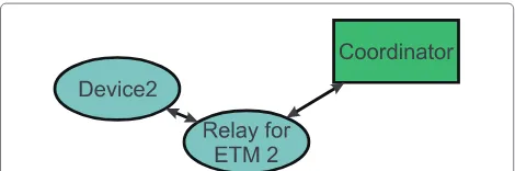
The aim of the proposed extended topology mode (ETM) is to extend the area covered by the WSN and enable sen-sor nodes, which are not in the communication range of the coordinator, to still transmit their packets to the coor-dinator. This task can be handled by mesh networks with routing strategies. However, the required protocols usu-ally are much more complex than in star networks and thus require increased overhead and power consumption. The advantage of our proposal is that the network organi-zation can be performed in the standard conform simple LLDN framework which is supplemented by the ‘relay for ETM’ node. This is a newly defined type of node different to the relay for RM of the previous subsection, but also stationary and mains powered.
The proposed schedule is based on opportunistic cod-ing, which enables forwarding of multiple packets in a single transmission. Like shown in [30], forwarding of a simple XOR conjunction of two incoming packets in a router node, enables the pairwise exchange of pack-ets in only three transmissions instead of four. In our proposal, it is necessary to exploit the limited resources available for each device in the LLDN framework. In the example shown in Figure 6, device2 and coordinator do not have a direct data link between them and thus use relay_for_ETM_2 to exchange the beacons and the data packets.
The schedule in Figure 7 shows the packet transmission in the extended topology. The relay_for_ETM_2 listens for the beacon from the coordinator and the data packet from device2 in the assigned time slots. With the assump-tion, that the retransmission slot is assigned and known a priori, the relay node has the possibility to use the
Figure 6Connection via relay node for ETM.Example of the spatial distribution in the extended star network with the relay for ETM node for forwarding the data of the two-hop neighbor.
retransmission slot for forwarding the data packet to the coordinator and in the same time slot, forwarding the bea-con to device2. These two packets can be encoded by XOR-ing them together to one packet. Both receivers, the coordinator and the device2, are able to decode this packet by XOR-ing it with their respective original information.
Periodical data transmission in SM leads to a worst-case delay between data generation and availability in the base station of one superframe duration, e.g. 10 ms. This guaranteed latency increases in ETM due to forwarding the data by the relay node to one and a half superframe duration.
The reception of the data packet in the retransmission slot is part of the LLDN framework and thus without changes for the coordinator. The device requires a small modification in the timing, because the listening of the beacon is not performed at the beginning of the super-frame, but in the retransmission slot. The scheduling of data packet transmission is the same like in the standard star topology. Forwarding the beacon enables the two hop device to synchronize to the LLDN network and orga-nize its schedule regarding the beacon information, e.g. Transmission State and Configuration Sequence Number. Similar to the RM, the placement of one or more relay nodes allows for optimization of the functionality of the network. As the energy analysis will show, the energy con-sumption in ETM is constant in all devices, so only the successful throughput can be optimized.
The required transmissions and receptions of the device within a superframe are a data packet transmission in the assigned time slot and the listening for the XOR-ed packet in the assigned retransmission time slot. Thus, the energy consumption per superframe is constant and equals
EETM,Device=ETX,Data+ERX,XORed. (8)
The relay for ETM node performs listening for beacon, listening for data packet and transmission of the encoded (XOR-ed with beacon) data packet. The only possibility of saving energy could be skipping the encoded packet, when both reception attempts fail. In this analysis, we do not consider this optimization option, because skipping of the encoded packet leads to a longer listening period in the device, because it listens until a time-out. The constant need of energy per superframe in the relay for ETM is
EETM,Relay=ERX,Beacon+ERX,Data+ETX,Data. (9)
Data loss occurs, when either the data packet from the device to the relay or the retransmitted data packet from the relay to the coordinator gets lost. The probability that a data packet gets lost, characterized by PLR, is
Figure 7Schedule of ETM.Example of the schedule for the proposed extended topology mode (ETM).
In this analysis, we assumed the energy consumption due to the opportunistic coding (XOR operation) to be negligible.
6 Analysis
The comparison of the regular retransmission behavior in the LLDN network standard mode (SM) with the pro-posed retransmission mode (RM) and extended topology mode (ETM) is made based on energy consumption and on the probability of losing data packets. Finally, the place-ment of the relay for RM is optimized.
6.1 Energy consumption
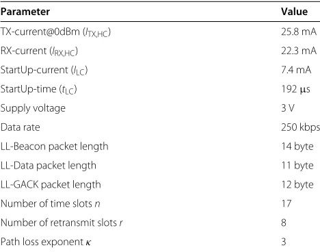
The energy consumption per superframe is calculated by Equation (2) (device) for standard mode, Equations 5 (device) and 6 (relay for RM) for retransmission mode, and Equations 8 (device) and 9 (relay for ETM) for extended topology mode. The energy, which is consumed dur-ing reception and transmission depends on transmission power, listening duration, packet length, and hardware specific features, like duration of PLL locking. The charac-terization of transceiver power consumption is described in [31], where the values from the datasheet are verified by measurements. We used the values for a Texas Instru-ments CC2520 transceiver for a supply voltage of 3 V and a transmission power of 0 dBm for all nodes for the following analysis (Table 1, [31]).
The parameters which specify the packet length are the sensor value quantization and the number of bits in the GACK. The settings in this analysis are 2 bytes for each sensor value in a LLDN network with a maximum of eight devices, which lead to 1 byte of GACK information. The resulting packet lengths including overhead are 14 bytes for each beacon, 12 bytes for a GACK packet and 11 bytes for the data packets. These settings enable a superframe duration of 10 ms with the proposed retransmission possibility.
The first step for comparing the different modes is to compute the consumed energy for each transmission and
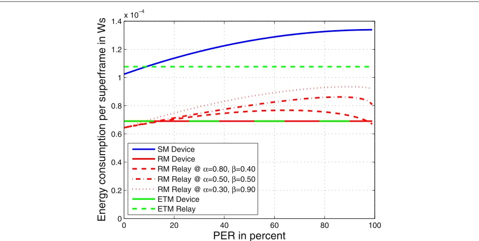
reception, considering the parameters for each mode. The second step is to calculate the number of transmissions and receptions, by evaluating the retransmission possibil-ities of Equations 1 and 4. The retransmission possibilpossibil-ities depend on the link qualities (PER) between the involved nodes. In Figure 8, the consumed energy per superframe by the device and relay nodes of the three modes as function of PER are compared. This common PER value represents different link qualities for each mode, which are described in detail below.
SM represents the default setup, where PERD2Cis valid between the device and the coordinator for the distance dD2C and packet lengthlData. The value PER in Figure 8 represents PERD2C for SM and RM. We assume that all other PERs, which are required for the analysis (PERD2R
and PERR2C), can be derived from PERD2C - which is
assumed to be known - simply by assuming the distances between transmitter and receiver and the transmission powers.
This calculation from a known PER1to a new PER2with the knowledge of the ratio of the two transmission powers
Table 1 Parameter used for analysis
Parameter Value
TX-current@0dBm (ITX,HC) 25.8 mA
RX-current (IRX,HC) 22.3 mA
StartUp-current (ILC) 7.4 mA
StartUp-time (tLC) 192μs
Supply voltage 3 V
Data rate 250 kbps
LL-Beacon packet length 14 byte
LL-Data packet length 11 byte
LL-GACK packet length 12 byte
Number of time slotsn 17
Number of retransmit slotsr 8
0 20 40 60 80 100 0
0.2 0.4 0.6 0.8 1 1.2 1.4x 10
−4
PER in percent
Energy consumption per superframe in Ws
SM Device RM Device
RM Relay @ α=0.80,β=0.40 RM Relay @ α=0.50,β=0.50 RM Relay @ α=0.30,β=0.90 ETM Device
ETM Relay
Figure 8Comparison of energy consumption.Comparison of the energy consumption due to transceiver activity in one superframe in the device and the relay in the three different modes.
(Et,1/Et,2), the ratio of the two distances (d1/d2), and the lengths of the packets (l1 andl2), can be done as shown in the Appendix. The described calculation is based on Rayleigh fading channel model with AWGN. This assump-tion relates to a worst case scenario in which no line-of-sight propagation component is available. Because in industrial environments a large variety of different propa-gation conditions can be found, we consider this simplifi-cation as acceptable [32].
The probability of transmission error is determined by the signal-to-noise ratio (SNR) at the receiver, which is proportional to the transmitted bit energy and inversely proportional to the distance between transmitter and receiver to the power of the path loss exponent (SNR ∼
Et/dκ). The only assumption regarding the propagation model is the path loss exponentκ, which we assume with κ =3.
In the analysis of this subsection, all nodes use the same transmission power, consequently a transmission energy ratio of one is used (Et,1/Et,2 = 1). The distances are defined bydD2R=α·dD2CanddR2C=β·dD2C, as shown in Figure 4. The spatial arrangement leads to the condition α+β≥1.
To analyze the behavior of the ETM, the value PER in Figure 8 is used to describe the link qualities between device and relay for ETM and relay for ETM and coordi-nator. The connection between device and coordinator is by definition not considered.
In Figure 8, we compare the energy consumption per superframe for device and relay of SM, RM, and ETM in
three different spatial configurations, characterized byα
and β. The consumed energy of the device in RM and
ETM is the same and constant (green-red solid line in Figure 8). This value is significantly smaller (reduction by 33% to 48%) than the energy consumption of the device in SM. Also the consumed energy in the relay for RM node is smaller than the energy consumption of the device in SM, when it cooperates with only one device. In that case, powering by a battery is possible. If the relay for-wards data from many devices, the power consumption would increase and mains powering should be consid-ered. The relay for ETM consumes a constant amount of energy, independent from the link quality and at PER val-ues higher than 9%, this consumption is smaller than that of the device in SM. As mentioned already for the relay for RM, the number of supported devices affects the energy consumption.
The main advantage of RM and ETM is the power-saving in the devices, where in RM this power-saving goes hand in hand with an improvement of the reliability (see subsection 6.2), while ETM achieves a larger coverage area. The total energy consumption of device and relay in RM and ETM is higher compared to the consumption of the device in SM, but this is a moderate cost compared to the benefits.
6.2 Lost data packets
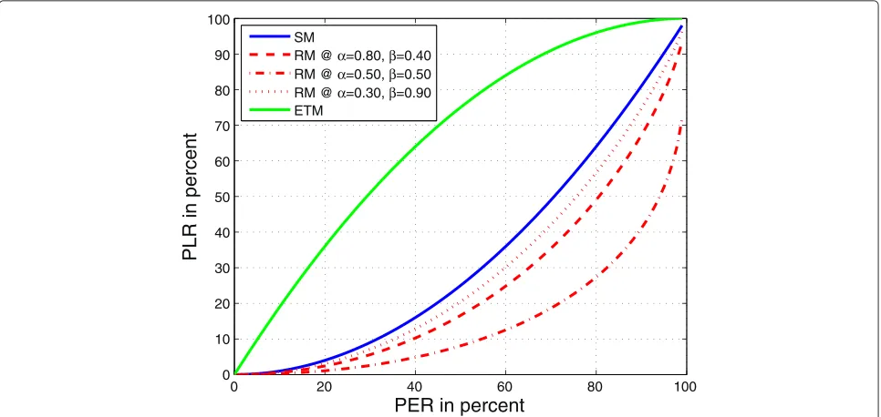
configuration and the PER, is evaluated. By PLR, we consider the lost packets after retransmission attempts. This is different to PER, where each lost packet between transmitter and receiver is considered. Equations 3, 7 and 10 describe the PLR for the corresponding mode.
If no retransmission would be offered, PLR would be equal to PER. The improvement with only one retrans-mission possibility in standard mode is represented by the ‘SM’ marked line in Figure 9.
The evaluation of the PLR in the ETM, where PER describes the link between device and relay as well as relay and coordinator, leads to the ‘ETM’ marked line in Figure 9. Here, we have to conclude that the advantage of a larger covered area has the disadvantage of a higher data loss.
The PLRRMin the RM is not only a function of the PER, but also the placement of the relay, which has an influence. Figure 9 shows that dependency for the three placement configurations (α and β) already used in Figure 8. The intuitively best choice of relay placement in the middle between device and coordinator (α = 0.5 andβ = 0.5) leads to the best performance with a reduction of PLRRM by up to 40% (at 90% PER), although the power consump-tion in the relay is not a maximum. The configuraconsump-tion
α = 0.3 and β = 0.9 has the same total transmission
distance (1.2·dD2C) like theα=0.8 andβ=0.4 configu-ration, but cannot reach its performance even at a higher energy consumption. This leads to the survey about the optimum placement of the relay for RM in the following subsection.
6.3 Spatial configuration in RM
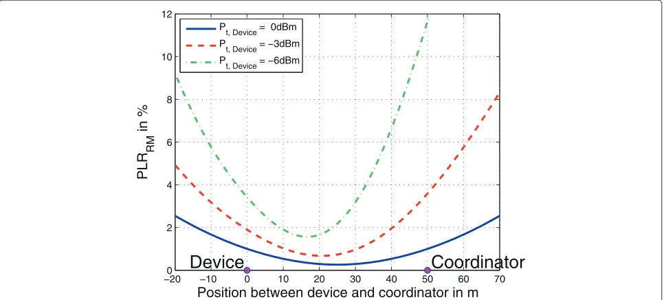
Figures 8 and 9 show that the position of the relay for RM can be optimized to achieve a network with low PLRRM at low power consumption. In the analysis of the spatial configuration in RM, we assume fixed positions of device and coordinator with a known PERD2C at 0 dBm trans-mission power forlData =88 bits long packets and a path loss exponent ofκ = 3. The device is placed at(0/0 m) and the coordinator in a distance of 50 m at(0/50 m). The PLRRM is calculated for different positions of the relay for RM node and different transmission powers of the battery powered devicePt,Device(0,−3, and−6 dBm) with the corresponding PER values and equation (7). The PER values are calculated as described in the Appendix.
The contour plot of Figure 10 shows lines of equal PLRRM in percent with different transmission powers of the device as parameter, assuming a PERD2C of 10%. If device and relay transmit with the same power Pt, the contour lines have their center exactly halfway between device and coordinator. With decreasingPt,Device, the cen-ter of the contour lines moves towards the device. This can also be better seen in Figure 11, where PLRRM is shown if the relay is located on the line connecting device and coordinator.
Of course, the reduction of Pt,Device results in higher data loss, but by placing the relay node according to the probability contours in Figure 11, the lowest possible PLRRMcan be achieved. Furthermore, the lower the trans-mission power of the device, the more sensitive the error probability is against a wrong placement of the relay.
0 20 40 60 80 100
0 10 20 30 40 50 60 70 80 90 100
PER in percent
PLR in percent
SM
RM @ α=0.80,β=0.40 RM @ α=0.50,β=0.50 RM @ α=0.30,β=0.90 ETM
−50 0 50 −20
−10 0 10 20 30 40 50 60 70
0.5
0.5
1
1 1
1
2
2
2 2
2 5
5
5
5
1
1
2
2 2
5 5
5
5
5 2
5
5
5
PLR
RM
in %
y Position in m
x Position in m
Device
Coordinator
P
t, Device = 0dBm
P
t, Device = −3dBm
P
t, Device = −6dBm
Figure 10Spatial distribution of PLRRM.Positions of the relay for RM node to establish PLRRMvalues of 1%, 2% and 5% with PERD2Cof 10% and different transmission power settings of the devicePt,Device.
7 Conclusion
The LLDN mode of the IEEE 802.15.4e standard offers a deterministic behavior for a WSN in star topology where each sensor node transmits up to 100 sensor val-ues per second. The standard already specifies a schedule with a specific time slot for GACK packets and thus the possibility of real-time retransmission within the same
superframe. First, we proposed the retransmission mode, where an additional relay for RM node allows retransmis-sion, if the data packet of the device is lost in the first transmission attempt of the device. The results are lower power consumption in the device and higher transmission reliability. This can be reached with optimized placing of the relay node, which is discussed in this work. The
−200 −10 0 10 20 30 40 50 60 70
2 4 6 8 10 12
PLR
RM
in %
Position between device and coordinator in m
Device
Coordinator
P
t, Device = 0dBm
P
t, Device = −3dBm
P
t, Device = −6dBm
minimum power savings in the device are 33% and can reach up to 50% at lossy channels.
The reliability improvement for RM in harsh industrial environment depends on the placement of the relay node. The Rayleigh fading channel model used in our analysis represents a worst case scenario with non-line-of-sight between the nodes, which should be less critical in prac-tical scenarios, especially when line-of-sight is present. In that case, rice fading channel model would be proper, but in our opinion, too optimistic, when the line-of-sight can-not be guaranteed. Furthermore, the RM enables better diversity due to transmission over two spatial different and thus uncorrelated wireless channels instead of two trans-mission attempts over the same wireless channel as in the LLDN mode.
The extended topology mode is the second proposal, which enables data transmission from a device, which has only a two-hop connection to the coordinator. It thus allows to significantly extend the spatial coverage. The power consumption of the device and the relay for ETM are kept low. The cost of this data forwarding is a higher probability of lost data packets.
Both proposed extension offer the advantage that they are compatible to the LLDN mode of IEEE 802.15.4e.
Endnote
aNote that minimizing the energy consumption of the
device does not necessarily lead to minimizing energy consumption of the whole network.
Appendix
PER as function ofdandEt
The spatial distribution of the nodes in a WSN lead to different PERs between all involved nodes. We want to derive the PERs from one reference link with known PER1. The reference link is characterized by the transmit-ted bit energy Et,1, the distance d1 between transmitter and receiver, and the length of the transmitted packetl1. The second link, for which we want to know the link quality (PER2), is characterized by d2, Et,2, and l2. The equations used below are based on a flat Rayleigh fading channel with AWGN. The proposed derivation is per-formed with only assuming the path loss exponent κ, which is 2 for free space propagation and increases in multipath environments.
The first step of the calculation is to derive the bit error rateBER1from the known PER1of packets with lengthl1. We assume independent bit errors and no channel coding:
BER1=1−(1−PER1) 1
l1. (11)
The IEEE 802.15.4 PHY uses Offset-QPSK modulation with half-sine pulse shaping, which is equivalent to MSK, in the 2.4 GHz ISM Band, which has the same bit error
probability as QPSK [33]. Tse and Viswanath [24] describe the bit error probability of QPSK in a Rayleigh fading channel with AWGN
where SNR describes the signal-to-noise ratio at the receiver. This yields the known SNR1as
SNR1=
2(1−2BER1)2
1−(1−2BER1)2. (13)
In [24], SNR is defined as ‘average received signal energy per symbol time’ to ‘noise energy per symbol time’, SNR := Er
N0. The received bit energy is proportional to
Et/dκ. Thus, the relation between known SNR1and new SNR2can be expressed by
SNR1
SNR2 =
Et,1dκ2
Et,2dκ1
(14)
Thus the SNR2 of the second wireless link can be
expressed by the known SNR1, without knowledge about noise, antenna gain, etc. From (12) and (14), we find
BER2=
which finally leads to
PER2=1−
The authors declare that they have no competing interests.
Acknowledgements
This work has been supported by the Austrian COMET-K2 programme of the Linz Center of Mechatronics (LCM) and was funded by the Austrian federal government and the federal state of Upper Austria.
Author details
1Linz Center of Mechatronics GmbH, Altenbergerstr. 69, Linz 4040, Austria. 2Institute for Communications Engineering and RF-Systems, Johannes Kepler
University, Altenbergerstr. 69, Linz 4040, Austria.
Received: 18 December 2013 Accepted: 4 August 2014 Published: 9 August 2014
References
1. VC Gungor, GP Hancke, Industrial wireless sensor networks: challenges, design principles, and technical approaches. IEEE Trans. Ind. Electron.
56(10), 4258–4265 (2009)
3. IEEE,Part 15.4: Wireless Medium Access Control (MAC) and Physical Layer (PHY) Specifications for Low-Rate Wireless Personal Area Networks (WPANs).
IEEE Std 802.15.4-2006 (Revision of IEEE Std 802.15.4-2003). (IEEE, Piscataway,
2006)
4. CC2520, 2.4 GHz IEEE 802.15.4/ZigBee RF Tranceiver. Texas Instruments. http://www.ti.com/lit/gpn/cc2520. Accessed December 2007 5. MRF24J40, IEEE 802.15.4 2.4 GHz RF Transceiver. Microchip Technology
Inc. http://ww1.microchip.com/downloads/en/DeviceDoc/39776C.pdf. Accessed 18 Aug 2010
6. S Petersen, S Carlsen, WirelessHART versus ISA100.11a: the format war hits the factory floor. IEEE Ind. Electron. Mag.5(4), 23–34 (2011)
7. O Khader, A Willig, A Wolisz, WirelessHART TDMA protocol performance evaluation using response surface methodology, in2011 International Conference on Broadband and Wireless Computing, Communication and
Applications (BWCCA)(Barcelona, Spain, 26-28, Oct 2011), pp. 197–206
8. S-E Yoo, PK Chong, D Kim, Y Doh, M-L Pham, E Choi, J Huh, Guaranteeing real-time services for industrial wireless sensor networks with IEEE 802.15.4. IEEE Trans. Ind. Electron.57(11), 3868–3876 (2010) 9. IEEE,IEEE Standard for Local and Metropolitan Area Networks - Part 15.4:
Low-Rate Wireless Personal Area Networks (LR-WPANs) Amendment 1: MAC Sublayer. IEEE Std 802.15.4e-2012 (Amendment to IEEE Std 802.15.4-2011)
(IEEE, Piscataway, 2012)
10. F Chen, T Talanis, R German, F Dressler, Real-time enabled IEEE 802.15.4 sensor networks in industrial automation, inIEEE International Symposium
On Industrial Embedded Systems, 2009. SIES ‘09(Lausanne, Switzerland,
8-10, July 2009), pp. 136–139
11. F Chen, R German, F Dressler, Towards IEEE 802.15.4e: a study of performance aspects, in2010 8th IEEE International Conference On Pervasive Computing and Communications Workshops (PERCOM
Workshops)(Mannheim, Germany, 29, March 2010), pp. 68–73
12. RK Tripathi, YN Singh, NK Verma, Two-tiered wireless sensor networks - base station optimal positioning case study. IET Wireless Sensor Syst.2(4), 351–360 (2012)
13. O Liang, YA Sekercioglu, N Mani, A survey of multipoint relay based broadcast schemes in wireless ad hoc networks. Commun. Surveys Tuts.
8(4), 30–46 (2006)
14. F Cuomo, A Abbagnale, E Cipollone, Cross-layer network formation for energy-efficient IEEE 802.15.4/zigbee wireless sensor networks. Ad Hoc Netw.11(2), 672–686 (2013). Special Issue on Cross-layer design in ad hoc and sensor networks
15. JN Al-Karaki, AE Kamal, Routing techniques in wireless sensor networks: a survey. IEEE Wireless Commun.11(6), 6–28 (2004)
16. KSJ Pister, L Doherty, TSMP: Time synchronized mesh protocol, in
Proceedings of the IASTED International Symposium on Distributed Sensor
Networks (DSN08)(Orlando, Florida, USA, 16-18 November 2008)
17. D Stanislowski, X Vilajosana, Q Wang, T Watteyne, K Pister, Adaptive synchronization in IEEE 802.15.4e networks. IEEE Trans. Ind. Inform.
PP(99), 1–1 (2013)
18. RAM Khan, H Karl, Mac protocols for cooperative diversity in wireless lans and wireless sensor networks. IEEE Commun. Surv. Tutorials.16(1), 46–63 (2014)
19. P Ju, W Song, D Zhou, Survey on cooperative medium access control protocols. IET Commun.7(9), 893–902 (2013)
20. H Al-Tous, I Barhumi, Performance analysis of relay selection in cooperative networks over Rayleigh flat fading channels. EURASIP J. Wireless Commun. Netw.2012, 224 (2012)
21. JN Laneman, DNC Tse, GW Wornell, Cooperative diversity in wireless networks: efficient protocols and outage behavior. IEEE Trans. Inf. Theory.
50(12), 3062–3080 (2004)
22. K Srinivasan, M Jain, JI Choi, T Azim, ES Kim, P Levis, B Krishnamachari, The
κfactor: inferring protocol performance using inter-link reception correlation, inProceedings of the Sixteenth Annual International Conference
on Mobile Computing and Networking.MobiCom ‘10 (ACM, New York,
2010), pp. 317–328
23. K Srinivasan, MA Kazandjieva, S Agarwal, P Levis, Theβfactor: measuring wireless link burstiness, inSenSys ‘08: Proceedings of the 6th ACM Conference
on Embedded Network Sensor Systems(ACM, New York, 2008), pp. 29–42
24. D Tse, P Viswanath,Fundamentals of Wireless Communication(Cambridge University Press, New York, 2005)
25. H-J Körber, H Wattar, G Scholl, Modular wireless real-time sensor/actuator network for factory automation applications. IEEE Trans. Ind. Inform.
3(2), 111–119 (2007)
26. G Anastasi, M Conti, M Di Francesco, A comprehensive analysis of the MAC unreliability problem in IEEE 802.15.4 wireless sensor networks. IEEE Trans. Ind. Inform.7(1), 52–65 (2011)
27. L Tang, K-C Wang, Y Huang, Study of speed-dependent packet error rate for wireless sensor on rotating mechanical structures. IEEE Trans. Ind. Inform.9(1), 72–80 (2013)
28. T Rappaport,Wireless Communications: Principles and Practice, 2nd edn. (Prentice Hall PTR, Upper Saddle River, 2001)
29. L Tang, K-C Wang, Y Huang, F Gu, Channel characterization and link quality assessment of IEEE 802.15.4-compliant radio for factory environments. IEEE Trans. Ind. Inform.3(2), 99–110 (2007)
30. S Katti, H Rahul, W Hu, D Katabi, M Medard, J Crowcroft, XORs in the air: practical wireless network coding. IEEE/ACM Trans. Netw.16(3), 497–510 (2008)
31. A Berger, A Pötsch, A Springer, TDMA approach for efficient data collection in wireless sensor networks, inThe IEEE International Conference On Emerging Technologies and Factory Automation, 2012. ETFA 2012
(Krakow, Poland, September 17-21, 2012)
32. P Stenumgaard, J Chilo, P Ferrer-Coll, P Angskog, Challenges and conditions for wireless machine-to-machine communications in industrial environments. IEEE Commun. Mag.51(6), 187–192 (2013) 33. MK Simon, MS Alouini, Digital communication over fading channels: a
unified approach to performance analysis, inWiley Series in
Telecommunications and Signal Processing(Wiley, New York, 2000).
ISBN:9780471317791
doi:10.1186/1687-1499-2014-126
Cite this article as:Bergeret al.:Energy-efficient and reliable wireless sensor networks - an extension to IEEE 802.15.4e.EURASIP Journal on Wireless Communications and Networking20142014:126.
Submit your manuscript to a
journal and benefi t from:
7Convenient online submission
7Rigorous peer review
7Immediate publication on acceptance
7Open access: articles freely available online
7High visibility within the fi eld
7Retaining the copyright to your article
![Figure 2 LLDN mode superframe. Superframe in the LLDN mode of the IEEE 802.15.4e standard with separate Group Acknowledgement frame [9].](https://thumb-us.123doks.com/thumbv2/123dok_us/957847.1117269/4.595.57.542.568.704/figure-lldn-superframe-superframe-standard-separate-group-acknowledgement.webp)