doi:10.1155/2011/176393
Research Article
A Secure and Robust Connectivity Architecture for
Smart Devices and Applications
Taeshik Shon,
1Kyusuk Han,
2James J. (Jong hyuk) Park,
3Young-Sik Jeong,
4and Yang Sun Lee
51Convergence S/W Laboratory, DMC R&D Center, Samsung Electronics, Suwon 442-600, Republic of Korea 2Department of Information and Communication Engineering, KAIST, Daejeon 305-701, Republic of Korea 3Department of Computer Science and Engineering, Seoul National University of Science and Technology,
172 Gongreung 2-dong, Nowon-gu, Seoul 139-742, Republic of Korea
4Department of Computer Engineering, Wonkwang University, Jeonbuk 570-749, Republic of Korea
5Department of Information and Communication Engineering, Chosun University, 375 Seosuk-dong, Dong-gu,
Gwangju 501-759, Republic of Korea
Correspondence should be addressed to Yang Sun Lee,[email protected] Received 31 May 2010; Accepted 2 August 2010
Academic Editor: Damien Sauveron
Copyright © 2011 Taeshik Shon et al. This is an open access article distributed under the Creative Commons Attribution License, which permits unrestricted use, distribution, and reproduction in any medium, provided the original work is properly cited. Convergence environments and technologies are urgently coming close to our life with various wireless communications and smart devices in order to provide many benefits such as connectivity, usability, mobility, portability, and flexibility as well as lower installation and maintenance costs. Convergence has brought important change not only in the way we live but also in the way we think. It is the progress towards the attempt to create and to evolve new valuable services through the device convergence and fusion of in-home, office, and various environments around the personal mobile apparatus. Based on the dynamic trends of convergence, it is widely argued that the increased requirements on secure and robust connectivity between a variety of mobile devices and their applications provide us the era of real pervasive computing environment. Thus, in this paper, we present a novel connectivity architecture using RF4CE-(Radio Frequency for Consumer Electronics-) based wireless zero-configuration and enhanced key agreement approach. We analyze the security and performance of our proposed approach by the development of the prototype H/W and the construction of a testbed with CE and mobile devices.
1. Introduction
Nowadays, various smart devices and their applications are rapidly increasing according to the smart grid environment based on the interlocking and controlling of in-home smart appliances. It means that the rapid and explosive increase of the mobile device like smartphone and tablet PC will have a big impact on human life more and more. The enlargement of the mobile devices based on wired and wireless mobile communication technologies becomes one of the important factors that brings into various and new convergence services, and then promotes it. Such recent trends request the innovative paradigm about the various convergence services satisfying the individualized desire and consequently brings into the new converged services and
End user applications
IEEE 802.15.4 MAC and PHY
Figure1: RF4CE protocol architecture.
applied to diversified mobile devices and their WPAN environments. In last March 2009, a principal electronics 4 corp. (Panasonic, Philips, Samsung Electronics, and SONY) and ZigBee Alliance agreed to found the RF4CE (Radio Frequency for Consumer Electronics) consortium which is based on the existing IEEE 802.15.4 radio frequency [5–7]. Thus, the RF4CE standard can be one of the best candidates to fulfill the requirement for connecting heterogeneous mobile devices as well as various CE devices. In the security aspect, the link key generation scheme through exchanging key seeds is supported between the RF4CE enabled devices in order to provide reliable communication. However, the scheme provided by RF4CE standard has a vulnerability like Man-in-the-Middle (MITM) attack that key seed value can be exposed to the third party because the key seed is exchanged as a plaintext, and a third party can acquire and masquerade key seeds to generate link encryption key. Besides, the scheme also has the vulnerability of key seed retransmission and interception. In case key seeds are affected by a network attack like DoS (Denial of Service), additional seed retransmission is required because maximum 255 seeds should always be successively reassembled to generate a link key between nodes for secure communication. In case of Bluetooth, it has the risk of guessing of a PIN (Personal Identification Number) and the exposure of a random number according to a security mode [8,9].
In this paper, we first address the RF4CE-based zero configuration in order to provide easy control and contents sharing for a smart digital home device and applications. We then propose RF4CE-based enhanced key agreement using certificate-based mutual authentication to prevent cloned or comprised devices from joining RF4CE network and two-phase key seed distribution to provide efficient and robust key seed exchange.
The first contribution of this paper is that the proposed zero-configuration approach provides energy efficient, sim-ple, and easy configuration method to various devices during their connectivity control and data sharing. The second contribution is that the proposed RF4CE-based enhanced key agreement protocol provides a device identification and a forgery prevention using mutual device authentication, and generates a like encryption key without using all 255 key seeds which have the possibility of information disclosure to the third party, and resolves the vulnerability that key seed information is exposed to the third party by applying fundamental key seed encryption. Finally, we present a novel
secure and robust connectivity architecture based on RF4CE for smart devices and applications.
This paper is organized as follows. InSection 2, we deal with the introduction of RF4CE and security issues of the existing techniques. InSection 3, the proposed approaches are presented such as the ad hoc and infrastructure con-figuration and advanced pairing method. In Section 4, the actual system implementation and experiment are illus-trated. Discussion about the proposed approach is explained
inSection 5. Finally, we draw a conclusion of this paper in
Section 6.
2. Background
2.1. Overview of RF4CE. The RF4CE of the ZigBee alliance is one of the defacto WPAN standard technologies determined in March 2009 by the representative electric home appli-ances enterprises including Panasonic, Samsung Electronics, SONY, and Philips in order to prepare for the rapid increas-ing demand of bidirectional communication and remote control functionalities in CE market such as TV, home-theater, set-top box, DVD, and so forth.
As shown inFigure 1, RF4CE has the physical and MAC layer function of the IEEE 802.15.4 and it replaces the current IR remote to ZigBee RF4CE remote based on the low power consumption, nondirectional function including the LCD back lighting interference avoidance, and bi-directional communication. In case of the network layer in RF4CE, it has the light-weight structure in comparison with the preexistence ZigBee. Generally the RF4CE topology consists of 2 branch types’ nodes as called a target and controller. The target node performs the network initiation as the role of PAN coordinator similar with ZigBee network. In case of a controller node, it can search the network coordinated by the target node and request a connection and it generally works as a remote controller [7,8].
RF4 CE Wi-Fi Zero-config module Application
TV PC
Mobile terminal
RF4 CE Wi-Fi Zero-config module Application
RF4 CE Wi-Fi Zero-config
module Application
AP or Ad hoc
Figure2: Overall environment of zero configuration approach.
extension of WPS is hence progressing in Wi-Fi alliance [10–13].
RF4CE can provide the basic security functionalities such as frame encryption and data authentication in MAC layer because it is based on IEEE 802.15.4 specification. In the network layer of RF4CE, it first generates 128 bits link encryption key and stores the key in the pairing table after finishing the pairing process, and then the encryption key is utilized for secure data transmission. In the process of distributing the key seeds, it establishes secure channel between nodes. At this time, a controller and target node first performs the pairing process, and then checks the security capability option of the pairing request node. In case the correspondent node supports the security function, a key seed distribution process is performed. During the key seed distribution, the key seed values of the maximum n are delivered to a controller and then the same secret key is generated in an end-to-end. At this time, the maximum n of the transmitted key seed value is 255. In each node, the key seed value is reassembled through the XOR operation and then generates the link encryption key [6, 7,12, 14]. However, the key seed values have the vulnerabilities such as data interception, masquerading, and denial-of-service by the third party as well as MITM attack because of being transmitted to the plaintext state without providing an encryption or any security functions. Therefore, the key seed wiretapping by malicious users should be fundamentally prevented, and a solution for forgery of seed value itself and a sequence number of a key seed frame is required, too. In order to prevent DoS attack, it is necessary to support tolerant and resilient capability to prepare for interrupting the normal key seed distribution and secret key generation. There is the protection method of the key seed value through an encryption by using a predistributed master key as a simple solution for solving this problem between nodes. However, there remains still security issues like a node capture and distribution the master key safely.
Recently, several researches related to connectivity and control platform such as universal control, home sensor
service, and media processing multimedia platforms. In [15], the authors presented RF4CE-based remote control frame-work, however, it does not describe security analysis and performance analysis to address the proposed architecture’s superiority. Some researches [16,17] showed the multimedia processing platform based on p2p network and PTP/IP. In addition, sensor network platforms are suggested to show the applications using various connectivities in [17, 18]. However, such researches cannot provide enough security aspect and robustness.
3. Proposed Approach
In this section, we present novel connectivity architecture with zeroconfiguration and advanced pairing approach based on RF4CE. The zero-configuration approach is required to provide simple and easy connection between various Wi-Fi supported devices. And the proposed pairing scheme is good alternative for complementing the vulnera-bilities of the existing RF4CE key agreement scheme.
3.1. Ad Hoc and Infrastructure Connection Mode. We first show the zero-configuration approach supporting Wi-Fi ad hoc and infrastructure mode. Figure 2 gives an overview of the proposed RF4CE-based zero-configuration approach. The proposed approach consists of three representative devices such as mobile terminal, PC, and TV. It can be applied to various CE and IT devices supported by RF4CE and wireless interface like Wi-Fi.
Wi-Fi Zero-config
module Application
TV PC
Mobile terminal
RF4CE Wi-Fi
Zero-config module Application
RF4CE
Wi-Fi Zero-config
module Application
RF4CE
2. Wi-Fi connection between devices
Wi-Fi connection RF4CE connection
1. Establishing RF4CE connection,
and then sharing zero-configuration information Ad hoc connection
mode
Figure3: Ad hoc connection mode in zero configuration approach.
both infrastructure mode based on Access Point and ad hoc mode connection. The zero-configuration architecture capabilities can be performed by the distinguished features of RF4CE such as NLOS (No Line-Of-Sight or field of vision limitations) feature, bidirectional capability, reliable com-munications, power consumption, and true interoperability between vendors’ products. In aspects of our implementa-tion, we assume that the architecture has RF4CE and Wi-Fi RF interface. Thus, it can perform energy efficient power control, Wi-Fi zero configuration and exchanging control command by RF4CE and high-speed data transmission by Wi-Fi. The zero-configuration module supports lower layer’s RF interfaces, zero-configuration component, and RF inter-face controller. In other words, the zero-configuration core module performs RF interface control and management, and zero configuration of Wi-Fi network based on RF4CE control channel. Application components have a variety of application service profiles to provide remote control service, energy efficient power control, and content sharing. If more application profiles are added on our devices, they can work with other devices using the same application profile based on the zero-configuration architecture.
As we already mentioned about two kinds of zero con-figuration modes, there are two connection modes like AP and ad hoc for Wi-Fi zero configurations using RF4CE. The proposed architecture can support ad hoc and Infrastructure modes when a device requires making a connection with other devices with Wi-Fi.
Ad hoc connection mode is described in Figure 3. In ad hoc mode, there is no access point device and only exist RF4CE-based mobile and CE devices. For explanation, we assume that there are mobile terminals, PC, and TV devices. First, a mobile terminal tries to establish RF4CE network performing device discovery and pairing procedure.
In case of secure communication, secret key seed values can be shared if each corresponding devices are configured as security enabled. After constructing RF4CE control channel like bold line ofFigure 3, a mobile terminal distributes ad-hoc connection information such as private IP, SSID, security material, XML profile, and so on, to already existing RF4CE pairs. Each RF4CE connected devices establish Wi-Fi ad-hoc connection as illustrated in the dotted line ofFigure 3.
Infrastructure connection mode is described inFigure 4. In infrastructure mode, we assume that there exists Wi-Fi access point device and at least one device has a preconnected Wi-Fi connectivity. The preexisted Wi-Fi connection is described as the double-dotted line ofFigure 4. The overall environment is the same as ad hoc connection mode, however, access point is added. Basically, in infrastructure mode, the discovery and pairing procedure to establish RF4CE network is performed as ad hoc mode. RF4CE control channel is illustrated as the bold line in Figure 4. During RF4CE network establishment, a user’s mobile terminal collects an existing Wi-Fi connectivity from the rest of devices in RF4CE network, and then requests the Wi-Fi connection information to the device with Wi-Fi connectivity. After getting Wi-Fi connection information, the mobile terminal distributes the Wi-Fi information such as SSID, authentication mode, security key, XML profile, and so on, to the devices connected by RF4CE. Finally, the device which received Wi-Fi connection information makes a Wi-Fi connection, which is illustrated in the dotted line inFigure 4. If all members in RF4CE network can support security, the Wi-Fi zero configuration data will be delivered by secure communication.
Wi-Fi Zero-config
module Application
TV PC
Mobile terminal RF4CE
Wi-Fi Zero-config
module Application
RF4CE
Wi-Fi Zero-config
module Application
RF4CE Infrastructure
connection mode
3. Wi-Fi connection
Wi-Fi connection Existing Wi-Fi connection RF4CE connection
1. Existing Wi-Fi connectivity
2. Obtaining AP connection info from PC using RF4CE, and then sharing the AP connection information between MT and TV
Wi-Fi AP
Figure4: Infrastructure connection mode in zero-configuration approach.
We first present a mutual authentication process between devices entering RF4CE network is performed to provide enhanced RF4CE key agreement with two-phase key seed distribution based on a certificate like Mobile WiMAX [1]. In the device authentication of the IEEE 802.16 standard called Mobile WiMAX, it prepared for a forgery attack like a cloned SS by using a certificate applied in the manufacturing process [19–21]. In other words, we concentrate on the authentica-tion of the devices itself, however, it can verify whether a device participating in the RF4CE pairing process is normally manufactured or not. It also decreases the possibility of a masquerading attack in which a compromised controller or target participates in key seed allocation process.
As shown in Figure 5, a controller and target node providing a certificate each other perform a mutual authen-tication process before the pairing process starts. First, the controller receiving the target certificate confirms whether the certificate is provided from an authenticated target through the verification process of CA (Certificate Author-ity) signature, and then the controller delivers its own certificate,UID (Unique ID) and SEK R(Seed Encryption Key Random number) values which are used during key seed distribution. The UID and SEKR is a kind of a random number selected arbitrarily and they are encrypted by target’s public key with the signature of a controller after applying hash-function. TheUIDvalue is used as an argument at the key seed allocation process and the SEK Ris used in selecting a key seed encryption function. In a target side, the target certificate is verified, and then the UID value, SEKR and a controller’s signature are decrypted by the target’s private key. In addition, the target verifies the controller’s signature to calculate the hash value ofUIDand SEKRfor confirming UID and SEKR values. Therefore, the target authenticates
Start pairing procedure Verify
certificate
Verify Target’s certificate
Request Mobile terminal
(controller device)
Epub target[UIDSEK Rsignpriv controller
[h(UIDSEK R)]]controller’s cert
PC, TV, and so forth (target device)
Figure5: Mutual authentication, key parameters.
that the controller is a node requesting a pairing to target through the hash value and signature verification, and then it finishes all mutual authentication process.
during key seed distribution, while our protocol provides the secure protection for the initial key seed distribution. In the pairing phase (Figure 5), controller device can verify target’s certificate and obtain the public key of the target. Anyone who eavesdrop the communication cannot know or modify SEKRsince SEKRis encrypted with accompanying hashed value. The message from controller device can be easily authenticated by target’s private key, while previous methods do not provide the message authentication in this phase.
First, the proposed quick mode is performed with the procedure as described in Figure 6. A target node delivers randomly generated N seeds (N ≤ 255) to the controller. In each side, the controller and target can select the same n (n≤N) seeds among N seeds, and then they are used for generating the same link encryption key. In order to select n seeds, each node utilizes the random selection mask function which generates a random number with the size of 255 bits using the address and the UID previously shared in the authentication procedure andIVassignment process, separately. For example, the bit string of generated 255 bits becomes a criterion of selecting the nth key seed. In other words, each 0 or 1 of nth bit can be applied to a simple masking scheme to decide the transmission of a key seed value. In addition, we can transmit the only selected n key seeds by the masking result to a controller as a modified quick mode. The former quick mode is a key seed distribution method to provide the tolerance against DoS or intercept attack in comparison with the existing solution because it makes it difficult for attackers to know which seeds are used for key generation. When compared to a maximum 255 key seed transmissions of the existing key seed distribution, the modified quick mode is a way to focus on the transmission efficiency because of distributing only selected n key seeds. Therefore, the quick mode brings the effect of reducing the computation time since a link encryption key can be generated by using few numbers of seeds. In addition, there is the advantage to make difficult for guessing a link key in case some key seeds are exposed to the third party. In quick mode (Figure 6), the communication overhead is reduced to n (≤255) times communications while RF4CE standard requires 255 times communications. In order to generate the shared key using quick mode, an adversary should know n seeds that are randomly selected in 255 seeds. Also, the selection of n seeds needs the shared UID that is securely transmitted in the pairing phase (Figure 5). Thus, our protocol provides more efficiency in key seed distribution than current standard without threaten the security.
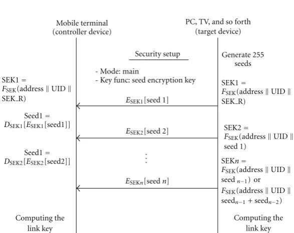
In case of the main mode, the proposed main mode is performed with the procedure as described in Figure 7. All key seeds up to 255 are transmitted to a node like the RF4CE standard, however, all seed values are encrypted by using all different SEK (seed encryption key) in order to solve the problem of key seed distribution as a plaintext. We can calculate each seed encryption key by following equations. First, the SEK1for encrypting the initial key seed value is derived by (1) using UID, IV, and SEK R of the mutual authentication procedure as the arguments ofFSEK()
function. For the generation of the SEKn, we can use (2) or (3) with the enumerated SEKR of 254 bits. If the nth bit of SEKRis 0, theFSEK() function of (2) is applied to make SEKnofnth key seed value. If not, (3) is used. The distributed all key seeds are not only encrypted by using all different encryption keys, but also cause more computation and time cost to guess a SEKieven in case a special key is exposed by the third party. Thus, the main mode can reduce the threat of key exposure and forgery due to the key seed transmission of plaintext status:
In main mod (Figure 7), each seed is encrypted using SEK1,. . ., SEKn. Existing methods have the initial problem since they use the previously sent seed as the encryption key. When the first seed is known, all information is exposed. However, our proposed method uses SEKR for randomization. Depending on each bit of SEKR, com-putation of SEKn is decided as in (2) or (3). SEKR is randomly chosen by the controller device, and transmitted as encrypted. The probability that an adversary obtains SEK R is the same as the probability that an adversary breaks the public key cryptosystem. Since RF4CE is based on 802.15.4 ZigBee standard, we could consider deploying existing WSN key distribution methods. However, such protocols require intermediate entities such as base station, while our protocol provide the peer-to-peer key exchange only between controller device and target.
4. Experimental and Implementation Results
Mobile terminal (controller device)
Security setup
Seed 1
SeedN Random selection mask
=FRSM(addressUID)
Random selection mask
=FRSM(addressUID)
Generate 255 seeds Selectnseeds
amongNseeds
Computing the link key
Computing the link key (N=255)
. . . -Mode: quick
-Key func: random selection mask
PC, TV, and so forth (target device)
Figure6: Key seed distribution-quick mode.
SEK1=
FSEK(addressUID
SEK R)
SEK1=
FSEK(addressUID
SEK R)
SEK2=
FSEK(addressUID
seed 1)
SEKn=
FSEK(addressUID
seedn−1) or
FSEK(addressUID
seedn−1+ seedn−2)
Seed1=
DSEK1[ESEK1[seed1]]
Seed1=
DSEK2[ESEK2[seed2]]
Mobile terminal (controller device)
Computing the link key Computing the
link key
Security setup Generate 255 seeds
ESEK1[seed 1]
ESEK2[seed 2]
ESEKn[seedn] - Mode: main
- Key func: seed encryption key
. . .
PC, TV, and so forth (target device)
Figure7: Key seed distribution-main mode.
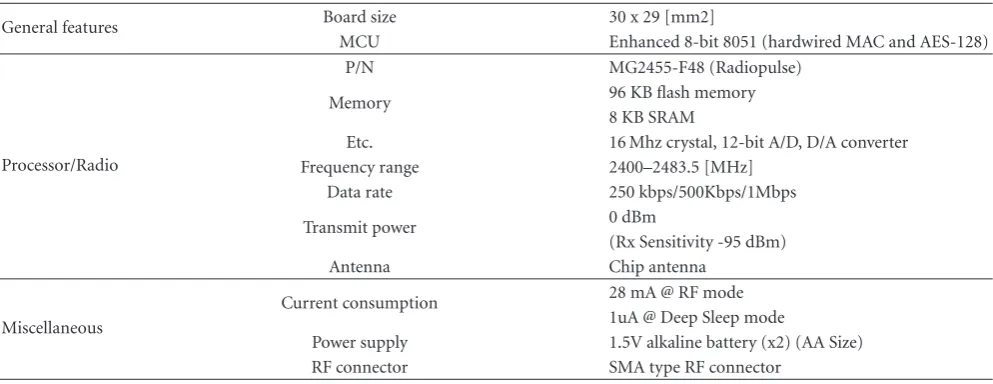
RF4CE test board. InFigure 8, it shows two kinds of RF4CE prototypes such as upper figure is RF4CE prototype with MG2455 RF4CE module [20] and lower figure is the layout of RF4CE prototype board. The specifications of the RF4CE evaluation board are shown in Table 1. MG2455 consists of 2.4 GHz RF transceiver, baseband modem, H/W MAC, 8051 MCU, and flash memory. Moreover, it has timer, UART peripheral, and normal I/O pins. Specifically, the MG2455 provides a few enhanced features as follows: Scalable Data Rate (250 kbps for ZigBee, 500 kbps and 1Mbps for private applications), Voice Codec Support, High RF RX/TX Power, 96 KB Embedded Flash Memory for Program Space, and Power Management Scheme with Deep Sleep Mode Support (under 1µA). Thus, we implemented H/W modules with IEEE 802.15.4 PHY/MAC as various types in order to be applied to mobile terminal and PC system. Specifically, we
used a small-size model with one-chip solution for a mobile terminal (e.g., Omnia phone) and a common model with enough size for multifunctional usage such as ZigBee and other IEEE 802.15.4-based simple applications (PCI board or USB board).
Figure 9is a real mobile phone with connectivity
archi-tecture module in our testbed. In order to make a testbed, we used Samsung Omnia phone (SCH-M490) and the prototype module is embedded as a type of small PCB in a battery case.
Figure 10is a prototype for PC system and it describes
Table1: Specification of RF4CE prototype board.
General features Board size 30 x 29 [mm2]
MCU Enhanced 8-bit 8051 (hardwired MAC and AES-128)
Processor/Radio
P/N MG2455-F48 (Radiopulse)
Memory 96 KB flash memory
8 KB SRAM
Etc. 16 Mhz crystal, 12-bit A/D, D/A converter
Frequency range 2400–2483.5 [MHz]
Data rate 250 kbps/500Kbps/1Mbps
Transmit power 0 dBm
(Rx Sensitivity -95 dBm)
Antenna Chip antenna
Miscellaneous
Current consumption 28 mA @ RF mode
1uA @ Deep Sleep mode
Power supply 1.5V alkaline battery (x2) (AA Size)
RF connector SMA type RF connector
Table2: Energy consumption for contents sharing scenario. TV status query
(times)
Contents list query (times)
Contents delivery (1 Mbytes)
Total energy consumption (mA) RF4CE + Wi-Fi With
Zero-configuration 2 (RF4CE) 2 (RF4CE) 447 (Wi-Fi) 97,991.8
Wi-Fi only 2 2 447 98,769.0
Bluetooth + Wi-Fi 2 (BT) 2 (BT) 447 (Wi-Fi) 98,121.0
have a PCI slot like desktop PC. The prototype for PC system consists of chipcon’s CC2420 as a radio chip (2.4 GHz Frequency, 250 Kbps, 0 dBm Output power), TI MSP430 16-bit RISC architecture with 12-16-bit A/D, and D/A converter as a microcontrol unit. Moreover, 116 Kb flash memories and 8 Kb RAM is installed as an internal memory and the board size of core module is 60×32 mm.Figure 10presents various built-in type of the prototype module in PC system.
Figure 10(a)shows that the prototype module is connected
by USB extension board to note-pc. In case of normal desktop PC, the module is installed by PCI slot as illustrated
inFigure 10(c). During debug and test, it is connected to the
development machine by USB port as shown inFigure 10(b).
4.2. Experimental and Demonstration of Connectivity Archi-tecture. In this section we constructed two testbed for zero-configuration approach and advanced pairing approach like Figures11(a)and11(b). First, the testbed of a RF4CE-based wireless zero-configuration in connectivity architecture for Smart and Easy Control of CE devices in order to validate the core functionalities with implemented zero-configuration modules has been created in our laboratory. As described in
Figure 11(a), the zero-configuration testbed consists of TV
(Samsung LED TV 8000), two Mobile terminals (Samsung Omnia phone SCH-M490), and Note-PC (Samsung SENS P50). Each device has RF4CE-based zero-configuration module and Wi-Fi interface. The two mobile terminals have the same application, however, it can be work for twofold: one is only for TV control, the other is for showing contents
sharing controller between TV and PC. Users can control TV and PC by using their own mobile terminal, remotely and freely.
On the other hand, the testbed of a simple RF4CE network for validating the fundamental functionalities of the proposed enhanced RF4CE key agreement system has been constructed in our laboratory. As shown in Figure 11(b), the RF4CE testbed is composed of two PCs as a controller and target simulator, and the simulators are connected with RF4CE prototype boards, separately. A discovery or pairing request packet from a controller node is sent to the target node, and then it is delivered to the simulator program using USB interface through UART serial socket. Thus, we can see that PC simulator is connected to RF4CE devices with USB-to-Serial interface, and then each node communicates on IEEE 802.15.4 standard.
5. Discussion of Secure and Reliable
Connectivity Architecture
Table3: Security analysis and comparisons.
Existing RF4CE Bluetooth Proposed System
Authentication
Feature None ECDH(Mode4) PKC∗.
Storage cost None Max2048 bits Max2048 bits
Computation cost None 3E∗∗ 3E∗∗
Integrity
Feature Packet level Packet level Packet level and quick mode
Storage cost 255∗80 bytes ∗∗∗ ≤255∗80 bytes
Computation cost 255 times ∗∗∗ ≤255 times
Confidentiality
Feature None (Plaintext) None (Plaintext) Main mode
Storage cost None None 128 bits
Computation cost None None <E
∗Public Key Cryptosystem;∗∗E denotes the exponentiation;∗∗∗BT does not use key seed distribution scheme.
(a) Prototype of the proposed module for Omnia (left) and its Debugging Board (right)
TTA 20p socket
Rufa
1
20 DC/
DC DC/
DC LEDs
EEPROM
Power S/W
MAX3232
Power S/W LEDs
Test S/W
Reset S/W
User INT
10
pin
header
(for
fusing)
10
pin
header
10
pin
header
Mini USB FPC
connector
RF module
RS-232
por
t
(b) Layout of the prototype and its debugging board Figure8: The Prototype of the connectivity architecture.
transmit 1 Mbyte-size content from PC to TV and measure the amount of energy consumed using the current con-sumption model in [22]. In the case of zero-configuration approach, RF4CE works for multimedia system control and Wi-Fi is used for delivering the content and the same con-figuration is applied to Bluetooth. But for the case of Wi-Fi, only Wi-Fi is used for both remote control and data sharing. Based on this experiment result, we claim that the RF4CE-based zero-configuration is more suitable to multimedia system control and contents sharing than the other solutions. In multimedia communications, energy is mostly con-sumed while devices exchange data and multimedia com-munications have not been much used for control. The age of various converged multimedia services is on its way and furthermore various hardware devices for these services are being developed. In light of this, sooner or later, these services and devices will be common in our
real life and we are going to use a control unit to remotely control them. As demonstrated in this section, multimedia control communications in using such various converged multimedia services also requires a nonnegligible amount of energy. In this sense, the proposed low-power RF4CE-based zero-configuration architecture can play a key role delivering a new device control experience with the users in the new environment of multimedia converged services
(a) (b)
Figure9: Mobile Phone (Omnia) and its embedded prototype module.
(a) (b) (c)
Figure10: Installed zero-configuration modules for PC extension (USB connection and PCI extension).
(i) Authentication. While the existing RF4CE standard does not consider any authentication method for the pairing and the key seed distribution, the proposed approach employs the authentication scheme that is used for the wireless network standards such as IEEE 802.16. Applying our approach, two entities in RF4CE communication can mutually authenticate each other during initial pairing with the preinstalled certificate issued by CA. Thus, the proposed approach is secure against not only the unauthorized device from attaching any authorized devices, but also any malicious entity from compromising or forging the node. In case of the Bluetooth, the PIN (Security mode 2, 3) or ECDH (Security mode 4) are deployed for the mutual authentication. Our proposed protocol has the additional computation cost of three exponentiations for supporting PKC (Public Key Cryptosystem) as same as the ECDH (security mode 4) of Bluetooth. In case of the computation cost, our proposed approach has the computation cost of three exponentiations due to the public key operation in the mutual authentication procedure. It means the public key operation is prevailed against other security operations. Thus, the authentication row inTable 1only has the computation cost and it shows the same level of burden compare to the cost of Bluetooth (mode 4).
(ii) Integrity. Integrity of key seeds shared among the nodes in RF4CE networks is guaranteed by FCS (Frame Check Sum) initially supported by RF4CE MAC Frame and MIC (Message Integrity Code) provided to packet in Network layer (NWK). Bluetooth also supports similar level of packet integrity. However, the previous methods could
not guarantee the security against modification or loss of the key seeds considering the integrity of transmitting max 255 number of key seeds. Instead, the proposed protocol provides the higher level of integrity than the previous methods by choosing n number of key seeds randomly from max 255 key seeds in quick mode. Note that we do not consider the integrity and confidentiality of key seeds of Bluetooth that does not use the key seed distribution. Thus, the existing RF4CE support a packet/frame level integrity function by the standard specification. And the proposed approach decreases the threat of the packet loss/interception and storage size (under 255∗80 bytes) by providing selective transmission of key seeds.
(iii) Confidentiality: The main mode of our proposed proto-col provides the high level of confidentiality in comparison with the previous methods that key seeds are transmitted in plain text during the key seed distribution, since every key seed is encrypted by different keys using 128 bits AES algorithm. In case of Bluetooth, it still has the vulnerability thatIN RANDfor generating Link Key is transmitted in a plain text in modes 2 and 3.
6. Conclusion
Digital TV (media server)
(a) Zero-configuration testbed (left)
simulator
(b) Advanced pairing testbed (right) Figure11: Testbed setup for the demonstration experiment (TV-Phone-PC).
Wi-Fi-based zero-configuration methods since RF4CE-based zero configuration is working on IEEE 802.15.4 standard technology. In case of advanced pairing, the novel approach to enhance RF4CE key agreement is presented according to these recent convergence trends. Our improved key agreement approach supports the mutual authentication using RF4CE device certification in order to resolve the threat of counterfeited or cloned devices. The quick mode of the proposed key seed distribution increases the possibility of the secure generation of a link encryption key against the disclosure to the third party and the DoS attack by providing the transmission of the selected key seeds. Key selection information is only shared between the paired nodes. The main mode solves the vulnerability of plaintext transmission through encrypting all transmitted seeds with different keys. In order to verify the zero-configuration and advanced pairing approach in the connectivity architecture, we imple-mented the prototype’s networking stack and its various prototypes H/W such as Samsung’s “Omnia” dongle for a mobile terminal and PC/note-PC side dongles. We pre-sented the implementation results with various verification scenarios using Omnia terminal, LED TV, and Note PC. The experimental scenarios demonstrated that the proposed architecture enables to construct a simple and easy control for an efficient smart home network between various devices. Moreover, we verified the feasibility and compared with the existing solutions of the proposed approach through analyzing security of Authentication, Integrity, Confidential-ity, and Known Attacks. From the various security analysis and real implementation, we can say that the proposed RF4CE key agreement approach is more robust than any other previous schemes and works efficiently with RF4CE nodes. Therefore, to the best of my knowledge, these results show the potential to bridge the convergence environments with smart devices and applications to our life using the proposed connectivity architecture with RF4CE-based Wi-Fi zero-configuration and advance pairing approach.
Acknowledgment
This research was supported by the Basic Science, Research Program through the National Research Foundation of Korea (NRF) funded by the Ministry of Education, Science and Technology (2010-0017023).
References
[1] Z. Jianliang and M. Lee, “Will IEEE 802.15.4 make ubiquitous networking a reality?”IEEE Communications Magazine, vol. 42, no. 6, pp. 140–146, 2004.
[2] E. Callaway, P. Gorday, L. Hester et al., “Home networking with IEEE 802.15.4: a developing standard for low-rate wire-less personal area networks,”IEEE Communications Magazine, vol. 40, no. 8, pp. 70–77, 2002.
[3] K. Gill, S.-H. Yang, F. Yao, and X. Lu, “A ZigBee-based home automation system,” IEEE Transactions on Consumer Electronics, vol. 55, no. 2, pp. 422–430, 2009.
[4] D. Egan, “The emergence of ZigBee in building automation and industrial controls,”IEE Computing and Control Engineer-ing, vol. 16, no. 2, pp. 14–19, 2005.
[5] ZigBee Alliance, “ZigBee specification: ZigBee document 053474r13,” Version 1.1, December 2006.
[6] ZigBee Alliance, “RF4CE Standard Specification,” Release 1.0, March 2009.
[7] IEEE STD 802.15.4-2006, “Part 15.4: Wireless Medium Access Control (MAC) and Physical Layer (PHY) Specifications for Low-Rate Wireless Personal Area Network,” September 2006. [8] Bluetooth Special Interest Group, “Bluetooth Core
Specifica-tion v3.0 + High Speed SpecificaSpecifica-tion,” Release 1.0, April 2009. [9] K. Scarfone and J. Padgette,Guide to Bluetooth Security, NIST
Special Publication 800-121, 2008.
[10] Wi-Fi alliance, “Wi-Fi Protected Setup Specification Version 1.0h,” December 2006.
[11] IEEE STD 802.15.4-2006, “Part 15.4: Wireless Medium Access Control (MAC) and Physical Layer (PHY) Specifications for Low-Rate Wireless Personal Area Network,” September 2006. [12] P. Baronti, P. Pillai, V. W. C. Chook, S. Chessa, A. Gotta, and
Y. F. Hu, “Wireless sensor networks: a survey on the state of the art and the 802.15.4 and ZigBee standards,”Computer Communications, vol. 30, no. 7, pp. 1655–1695, 2007. [13] Y.-H. Ha, “Dynamic integration of zigbee home networks into
home gateways using OSGI service registry,”IEEE Transactions on Consumer Electronics, vol. 55, no. 2, pp. 470–476, 2009. [14] N. Sastry and D. Wagner, “Security considerations for IEEE
802.15.4 networks,” inProceedings of the ACM Workshop on Wireless Security (WiSe ’04), pp. 32–42, October 2004. [15] B. Koo, T. Ahn, J. In, Y. Park, and T. Shon, “R-URC:
[16] B. Qureshi, G. Min, D. Kouvatsos, and M. Ilyas, “An adaptive content sharing protocol for P2P mobile social networks,” inProceedings of the 24th IEEE International Conference on Advanced Information Networking and Applications Workshops (WAINA ’10), pp. 413–418, 2010.
[17] P. Corcoran, “Architecture for a home media network based on PTP-IP connectivity techniques,” inProceedings of the 26th IEEE International Conference on Consumer Electronics, The Mobile Consumer (ICCE ’08), pp. 1–2, January 2008.
[18] P. William and S. Ravi, “An internet overlay architecture for global scale wireless sensor networks,” inProceedings of the Wireless Telecommunications Symposium (WTS ’10), pp. 1–6, 2010.
[19] IEEE Std 802.16-2004, “IEEE Standard for Local and Metropolitan Area Networks Part 16: Air Interface for Fixed Broadband Wireless Access Systems,” IEEE, 2004.
[20] IEEE Std 802.16e-2005, “IEEE Standard for Local and Metropolitan Area Networks Part 16: Air Interface for Fixed Broadband Wireless Access Systems, Amendment 2: Physical and Medium Access Control Layers for Combined Fixed and Mobile Operation in Licensed Bands and Corrigendum,” IEEE, 2005.
[21] Airspan Networks, “Mobile WiMAX security,” Release 1.0, September 2007.
[22] J.-S. Lee, Y.-W. Su, and C.-C. Shen, “A comparative study of wireless protocols: bluetooth, UWB, ZigBee, and Wi-Fi,” in