IJEDR1602193
International Journal of Engineering Development and Research (www.ijedr.org)1109
Open Loop Speed and Direction Control of DC Motor
Using Zigbee
Introduction, Circuit Diagram , Result, Application
Dhaval K.Patel 1, Nehal D.Tandel2, Samir I.Kuvawala 3
Student, Dep .of Electrical Engineering at Gidc Degree Engineering Colllage Abrama, Navsari Assistant Professor, Dept .of Electrical Engineering at Gidc Degree Engineering College Abrama ,
Navsari, Gujarat India
________________________________________________________________________________________________________
Abstract - As we know that in any industry, the system easily controlling is first requirements. For that we design a system which is wirelessly operated and control speed and direction of dc motor by using zigbee. Here we control a speed of a dc motor as per requirements with direction also by giving an input on laptop.
Keywords: DC motor, speed control, direction control, wirelessly controlling, zigbee.
________________________________________________________________________________________________________
I.INTRODUCTION
About dc motor summary speed control of dc motor many methods are available which are either be a mechanical or electrical for example armature control, field control, flux control method etc. but this methods required large size hardware to implement. So for easy control of speed and the direction control of dc motor the wireless speed and direction control of dc motor by using ZigBee is very much essential and economical to use. For variable ac voltage we can used a controlled rectifiers which are converted a variable ac voltage from fixed dc voltage. Recent development in the area of semiconductor technology have made faster, very small size microprocessors and microcontroller are available at in much reduced cost and easy control.
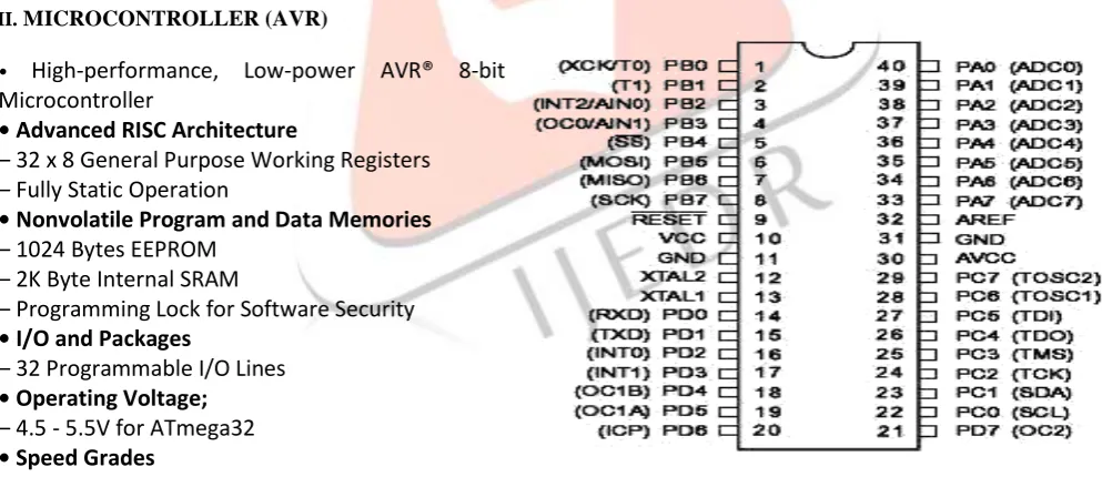
II.MICROCONTROLLER (AVR)
•
High-performance, Low-power AVR® 8-bit
Microcontroller
• Advanced RISC Architecture
– 32 x 8 General Purpose Working Registers
– Fully Static Operation
• Nonvolatile Program and Data Memories
– 1024 Bytes EEPROM
– 2K Byte Internal SRAM
– Programming Lock for Software Security
• I/O and Packages
– 32 Programmable I/O Lines
• Operating Voltage;
– 4.5 - 5.5V for ATmega32
• Speed Grades
– 0 - 16 MHz for ATmega32
FIGURE 1.ATMEGA32 PIN DIAGRAMIII.PULSE WIDTH MODULATION (PWM)
IJEDR1602193
International Journal of Engineering Development and Research (www.ijedr.org)1110
microcontroller having a 75% duty cycle then microcontroller provide a ¾ of power to the motor and finally the microcontroller provide a 100% duty cycle then microcontroller provide a full power to the motor.FIGURE 2.PULSE WIDTH MODULATION
IV.POWERSUPPLYOF5V&12V:-
FIGURE 3.POWER SUPPLY BLOCK DIAGRAM
Whole circuitry work on +5V, +12V DC power supply of 230V AC is applied to the transformer. By using transformer, rectifier, filters, IC regulators, etc. we get the desired output.
230 V
D1 D2
D3 D4
C1 C2
GND + 5 V 12V-5V
AC
IC
FIGURE 4.POWER SUPPLY CIRCUIT
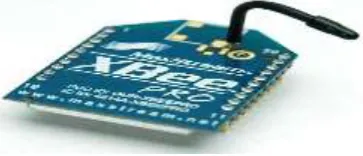
V.ZIGBEE:-
Zigbee is a specification for a suite of high level communication protocols used to create personal area networks built from small, low-power digital radios. ZigBee is based on an IEEE 802.15 standard. Though low-powered, Zigbee devices often transmit data over longer distances by passing data through intermediate devices to reach more distant ones , creating a mesh network; i.e., a network with no centralized control or high-power transmitter/receiver able to reach all of the networked devices.
IJEDR1602193
International Journal of Engineering Development and Research (www.ijedr.org)1111
Zigbee has a defined rate of 250 Kbit/s, best suited for periodic or intermittent data or a single signal transmission from a sensor or input device. Applications include wireless light switches, electrical meters with in-home-displays, traffic management systems, and other consumer and industrial equipment that requires short-range wireless transfer of data at relatively low rates.VI.DCMOTORS:
DC motors requires a basic understanding of the design and operating characteristics of the various type available: the series motor, the shunt motor, and the compound motor. Each type has unique operating characteristics and applications.
FIGURE 6.DC MOTOR
The relationship between torque v/s speed and current is linear as shown left; as the load on a motor increases, speed will decrease. The graph pictured here represents the characteristics of a typical motor. As long as the motor is used in the area of high efficiency (as represented by the shaded area) long life and good performance can be expected. However, using the motor outside this range will result in high temperature rises and deterioration of motor parts. If voltage in continuous applied to a motor in a locked rotor condition, the motor will heat up and fail in a relatively short time. Therefore it is important that there is some form of protection against high temperature rises. A motor's basic rating point is slightly lower than its maximum efficiency point. Load torque can be determined by measuring the current drawn when the motor is attached to a machine whose actual load value is known. We will select the most suitable motor for your application after receiving your information.
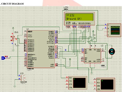
VII.CIRCUITDIAGRAM
IJEDR1602193
International Journal of Engineering Development and Research (www.ijedr.org)1112
motor D1 D2 D3 IC 12V-5V D4 LCDS1 S2 S3
S6 S5 S4
CONTROLLER AVR
MOTOR DRIVER IC Port A (PA7..P A0) Port B (PB0.. PB7) Port D (PD7.. PD0) Port C (PC7.. PC0) AC
FIGURE 8.CIRCUIT DIAGRAM
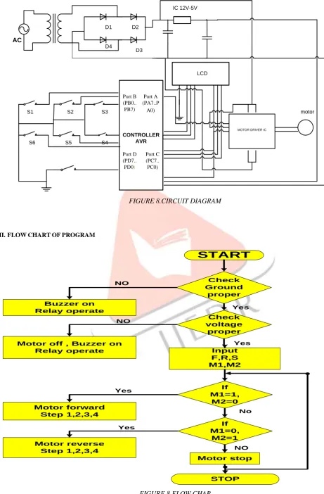
VIII.FLOWCHARTOFPROGRAM
Check Ground proper Buzzer on Relay operate Check voltage proper
Motor off , Buzzer on
Relay operate Input
F,R,S M1,M2 If M1=0, M2=1 If M1=1, M2=0 Motor forward Step 1,2,3,4 Motor reverse Step 1,2,3,4 STOP
START
Motor stop NO NO Yes Yes Yes Yes No NOIJEDR1602193
International Journal of Engineering Development and Research (www.ijedr.org)1113
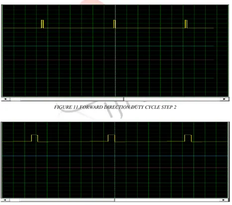
IX.PRACTICAL DUTY CYCLE OF MOTOR
1. FORWARD DIRECTION DUTY CYCLE OF MOTOR
FIGURE 10.FORWARD DIRECTION DUTY CYCLE STEP 1
FIGURE 11.FORWARD DIRECTION DUTY CYCLE STEP 2
IJEDR1602193
International Journal of Engineering Development and Research (www.ijedr.org)1114
FIGURE 13.FORWARD DIRECTION DUTY CYCLE STEP 4
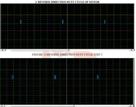
2. REVERSE DIRECTION DUTY CYCLE OF MOTOR
FIGURE 13.REVERSE DIRECTION DUTY CYCLE STEP 1
FIGURE 14.REVERSE DIRECTION DUTY CYCLE STEP 2
IJEDR1602193
International Journal of Engineering Development and Research (www.ijedr.org)1115
FIGURE 16.REVERSE DIRECTION DUTY CYCLE STEP 4
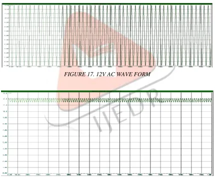
X.
Result
The direction control of the dc motor is achieved by using microcontroller programming. Direction
control has been achieved with higher performance, reliable operation and easy control.
FIGURE 17. 12V AC WAVE FORM
IJEDR1602193
International Journal of Engineering Development and Research (www.ijedr.org)1116
FIGURE 19. 5V DC WAVE FORM BY USING IC 7805
FIGURE20. INPUT WAVE FORM OF DC MOTOR
APPLICATION
- In many industry such as paper mills, rolling mills, printing machine tools, excavators and cranes etc the dc motor is used for way a product from one place to another on the conveyer belt.
- Robotics arm for peak and place purpose. - In electrical lab purpose.
REFERENCE
SOFTWARE work on Proteus
DC MOTOR CONTROL:
- SPEED AND DIRECTION CONTROL US 3,857,077 APPARATUS FOR DC MOTORS
- DIGITAL SPEED CONTROL CIRCUIT US 4,656,403 FOR A DC MOTOR
- DC MOTOR CONSTANT SPEED PWM US 6,731,082 B2 CONTROL
PROTECTION:
- DEVICE FOR DETECTING VOLTAGE US 4,795,971 FLUCTUATION
- PORTABLE GROUND FAULT US 5,034,726 DETECTOR
- POWER SYSTEM PROTECTION BOOK