Experimental Heat Transfer Study of Endwall in a Linear Cascade with IR
Thermography
Borja Rojo1,a, Carlos Jimenez1,b, and Valery Chernoray1,c
1Chalmers University of Technology, Department of Applied Mechanics, 412 96 G¨oteborg, Sweden
Abstract. This abstract presents an endwall heat transfer experimental data of air flow going through outlet guide vanes (OGVs) situated in a low speed linear cascade. The measurement technique for this experiment was infrared thermography. In order to calculate the heat transfer coefficient (HTC) on the endwall, it has been used an instrumented window with a controlled constant temperature in one side of a 5 millimeter Plexiglass in order to generate high temperature gradients and, therefore, by measuring the surface temperature one the other side of the Plexiglass, it is calculated the HTC. Due to the fact that Plexiglass material has not good optical properties at infrared spectrum, it has been used a thin layer of black paint (10-12μm) which has high emissivity (0.973) in the range of temperature that we are working. The Reynolds number for this experiment is 300000 in on and off-design configuration of the OGVs (on-design 25◦ and off-design cases are 40◦and -25◦ incident angle). Furthermore, the on-design case is run at two different Reynolds number, 300000 and 450000. During this experiments it can be seen how changing the inlet angle to the OGVs produces significant differences on the heat transfer along the endwall. The main objective for this investigation is to study the heat transfer along the endwall of a linear cascade so that it would be a well-defined test case for CFD validation.
1 Introduction
Demands from industry on improving the efficiency in all kind of energy systems, including aero engines, are lead-ing to focus on the research in more efficient propulsion systems. There are several ways to increase the energy ef-ficiency in jet engines, i.e. increasing by-pass ratio, raising the combustion temperature, decreasing the weight of any component in the aircraft etc.
OGVs are located at the outlet of the last stage of a low pressure turbine (LPT). The main purpose of adding this component to an aero jet engine is to connect the external casing and the core of these engines. The OGVs have to be able to carry all the loads from the internal to the external structure. Furthermore, through them it is possible to pro-vide access for pipes and electronics from the outer case to the shaft of the gas turbine. In addition to the structural and connecting functions, the OGVs also have an impor-tant aerodynamic role in a gas turbine engine due to the fact that they eliminate the swirl that comes from the LPT situated upstream. The flow around the OGVs is complex, there are secondary flows involved, boundary layer devel-opment and risk of flow separation as well. The design pa-rameters that are required, from an aerodynamic point of view, are the minimization of the pressure drop and the capability of withstand flow separation. Moreover, the pre-diction of flow separation and heat transfer becomes more complicated when the OGV has an inlet incidence angle far the on-design operation condition. Even though there has been performed numerous investigations on endwall heat
a e-mail:[email protected] b e-mail:[email protected]
c e-mail:[email protected]
transfer blades ([1]-[6]), very little experimental informa-tion is available in the field of the OGVs.
This paper is focused in the study of the heat transfer on the surface of a vane and endwalls situated in a low-speed linear cascade. The heat transfer study performed can help to understand better the complex heat transfer mechanisms involved in this case, and hence, the informa-tion can be used for CFD validainforma-tion purposes. Knowing the heat transfer mechanisms involved can lead to predict ac-curately the maximum temperature or thermal load on the surface of this component, and therefore, estimate the cool-ing if needed or select a lighter material that can handle the predicted thermal loads without melting or being sensitive to creep. This work is a continuation of previous investiga-tion in a large-scale linear cascade performed at Chalmers University of Technology [7],[8]. An additional motivation for this work is the comparison between the experimental results using two different heat transfer measurement tech-niques.
2 Experimental Facility
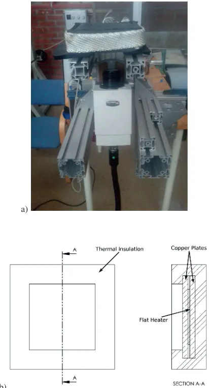
These experiments were performed in a low-speed linear cascade located in Chalmers University of Technology. The facility (see figure1) consists of a centrifugal fan (30 kW), a wide angle diffuser, a settling chamber where the out-let flow has not big wakes which were generated on the centrifugal fan, a two-dimensional contraction chamber, an inlet-section and a test section with boundary-layer suc-tion. The test section is composed by 2 parallel discs where the inner discs constitute the upper and lower endwalls of the OGVs (for more details see [9]).
The working area has a cross section of 240x1200 mm. In the test section there are located 4 OGVs and the pitch
a)
b)
Fig. 1.a) Linear cascade sections. b) Test section. [9]
between them is 240 mm. There is a vane which is instru-mented for heat transfer measurements and 3 more made of plastic material. In order to control the periodicity in the test section, there are 2 tail-boards attached to the topmost and bottommost vanes. It has been tested the periodicity by measuring the static pressure on the vanes and by check-ing the wake profiles downstream the trailcheck-ing edge of the vanes. The flow measurement procedure is explained in de-tail in [10]. The 4 OGVs are bolt to a Plexiglass wall. Fur-thermore, the level of the incoming flow turbulence inten-sity was adjusted by a turbulence grid which is located 700 mm upstream of the cascade. The OGVs are a 2D profile which is extended in the span direction.
3 Theoretical Model
For measuring the HTC on the linear cascade endwall, an instrumented window has been designed. In order to be able to measure the HTC, it is measured the temperature drop between two surfaces of the same body (in this case, a Plexiglass flat plate). Figure2shows the theoretical model that is used to explain the HTC measurement technique. All the terms can be calculated as:
qcd=
k
t(Tal−Tplexi) Conduction heat flux (1)
qcv=h(Tplexi−Tair) Convection heat flux (2)
Fig. 2.Theoretical model for the HTC measurement.[11]
qradσT4plexi−σTeq4 Net radiation heat flux (3)
Wherekis thermal conductivity of the Plexiglass which is 0.2 W m−2K−1, t is the thickness of Plexiglass which is 5 mm,Tal is the temperature on the interface between
the Plexiglass and the aluminium (see figure3) which is heated by 4 flat heaters,Tplexi is the temperature on the
external surface which is measured with the IR-camera,
Tair is the temperature of the air flow through the linear
cascade far enough from the heated endwall,is the ther-mal emissivity of the surface of the Plexiglass which has been painted using the Nextel Vetel-Coating 811-21 from Mankiewicz Gebr. & Co and its value is constant in our range of temperatures (0.973),σis the Boltzmann’s con-stant (5.67·10−8W m−2K−4) andT
eqis the equivalent
am-bient temperature which is used to estimate the heat losses via radiation to the surroundings of the endwall. In this case, the convective heat transfer coefficient is high enough so that all the surroundings are at the air temperature. Fur-thermore, it has been measure with an IR-camera the em-pirical value of this parameter. Not taking into account this term can lead to an additional error of 3 to 10% (depending on the wall temperature in each point).
qcd=qcv+qrad (4)
Afterwards, doing energy balance (eq.4) it can be ob-tained the measured HTC orh(eq.5).
HTC=
k
t(Tal−Tplexi)−(σT4plexi−σTeq4)
Tplexi−Tair
(5)
4 Experimental Setup
4.1 Instrumented Window
As it is described in section3, an instrumented window has been designed for obtaining the heat transfer on an endwall situated in a low-speed linear cascade. In order to design this window, it had to be taken into account several issues that affect the accuracy of the heat transfer measurement.
First of all, the Plexiglass plate which is situated in be-tween the air flow and the aluminium plate has to be at-tached to the aluminium plate so that there is no air gap (100μmair gap leads to 1.5◦C error in the measurement).
a)
b)
Fig. 3.a) Exploded view of the instrumented window. b) Cross
section view.
Therefore, it is critical to have a good surface contact be-tween this two flat plates. Then, the Plexiglass plate is at-tached to the aluminium plate bolting them with plastic screws. The reason for using plastic screws is that they have almost the same thermal conductivity as the Plexi-glass and hence, they would not change the HTC in the surroundings of these screws.
Furthermore, the window needs to be isolated from the steel frame where it stands on the linear cascade. If the aluminium plate touches this steel frame, most of the heat would go through the steel plate to the air flow and there-fore, it would not be any temperature gradient on the Plexi-glass. In order to isolate the aluminium from the steel plate, a plastic frame has been installed on the instrumented win-dow.
In addition, it is added in the back of the four heaters an aluminium plate. This plate has 2 functions. The first one is that it can be used to improve the contact between the heaters and the aluminium plate that provides the uniform temperature on the back of the Plexiglass. The second one is that it helps to have a more uniform temperature distri-bution in the window.
Finally, the insulating material situated on the back of the last aluminium plate adds more uniformity to the tem-perature distribution inside the instrumented window.
a)
b)
Fig. 4.a) Picture of the calibration process of the IR-camera. b)
Drawing of the calibration tool.
4.2 IR-Camera
In order to measure the temperature distribution on the end-wall and further compute the HTC, an infrared cam-era is used. This is a MWIR Phoenix Camcam-era System with a resolution of 320x256. This camera has been used in pre-vious experiments in a large-scale low-speed annular cas-cade rig (see [12], [13]). Before the experiment starts, the camera must be calibrated and a non-uniformity correc-tion is applied. In order to perform this set up for the IR-camera, it is needed to provide a uniform temperature over a surface. For this purpose, a calibration tool has been de-veloped in our lab.
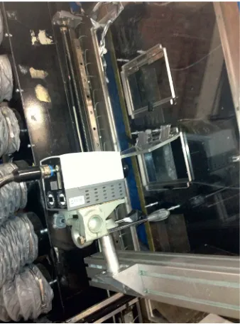
con-Fig. 5.IR-camera pointing at the instrumented window during the experiments.
trolled constant temperature so that it is possible to provide as many reference temperatures as are needed for the cal-ibration of the camera. The calcal-ibration is done by looking at 5 reference temperatures which are in the range of the expected temperatures that are measured during the exper-iment. For the non-uniformity correction it is needed a cold source (ambient temperature) and a hot source (50◦C). The accuracy of the IR-camera itself is 0.01◦C, but Finally, the accuracy of the IR-camera is about 0.1◦C due to the fact that the calibration tool has that precision.
Furthermore, it is needed to provide optical access to the camera. On one side of the linear cascade is located the instrumented window for the heat transfer measurement and on the other there is a Plexiglass window which has a low transmissivity in the infrared spectrum that this IR-camera is sensitive to (3-5μm). Therefore, there are several ways to solve this problem. It can be used a special mate-rial that has high transmissivity in our range of interest and substitute the Plexiglass by this material (at least in some important locations) or a few small windows can be per-formed with a fast opening system so that the hot endwall does not feel the flow changes during a big enough period of time so that an IR image can be taken. It is important that the frame rate of this IR-camera is around 60 Hz dur-ing this experiment, but it can be much higher by reducdur-ing the camera window size. This frame rate is fast enough to capture the needed amount of pictures and to average them within a period of time where the temperatures keep con-stant.
5 Results
5.1 On-Design conditions
For on-design conditions, the flow angle is 25◦ and the Reynolds numbers are 300000 and 450000. Figure6shows the results from the 300000 Reynolds number cases. It is important to point out that as it described in section3, the
a)
b)
Fig. 6.a) HTC distribution on the endwall without including
ra-diation losses. b) HTC including rara-diation losses.
radiation heat transfer mechanism influences the results. Especially on the areas where there is higher temperature on the endwall, and therefore where the HTC is lower, the difference between analyzing the results with and without the radiation correction can lead to a 10% error on the HTC calculation. There can also be seen that there is no separa-tion in this case. Looking at the endwall, in the areas in be-tween the two vanes, the HTC is decreasing in the stream-wise direction. This is a similar behaviour as a flat plate case where the flow is fully turbulent. On the suction side of the vane it can be appreciated an area with a very low HTC close to the trailing edge that will change its position for the different cases.
Figure 7 shows the on-design case with a Reynolds number which has been increased to 450000. There is an expected increase of the HTC in all the areas compared with the previous case due to the fact that the Nusselt num-ber is proportional to the Reynolds, and the HTC is propor-tional to the Nusselt. In this case there is almost no differ-ence in the HTC distribution on the endwall compared to the lower Reynolds on-design case. The main difference is
Fig. 7.HTC on-design case with an axial Reynolds number of 450000.
that the area with a low HTC on the suction side has been displaced downstream.
Furthermore, in both cases, there is a hot spot on the leading edge. There, the HTC achieves its highest value. This area is very important because of the cooling of this area can be critical to avoid structural damage on this com-ponent.
5.2 Off-Design conditions
Off-design conditions are very interesting because of the risk of flow separation when there are changes on the inci-dent angle to the OGV. The first off-design case is shown in figure8. The flow incident angle for this off-design case is 40◦. It can be clearly seen that there is no flow separation for this case. The flow impinges on the pressure side close to the leading edge and it is generated a vortex that rolls up downstream. Due to the adverse pressure gradient, this vortex is increasing its size. It would be expected to see also the effect of this vortex on the HTC of the vane close to the endwall affecting the flow around this vortex. In ad-dition, comparing on-design case and this case, the flow on the suction side follows almost the same pattern. The area with a low HTC on the suction side, which has been discussed in the previous cases, is displaced upstream.
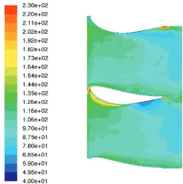
Figure9shows the second off-design case studied. In this case, the incident angle is -25◦. As it can be seen very clearly in figure9, there is flow separation on the pressure side. There is a separation bubble that decreases the HTC in between the flow and the endwall. Furthermore, the flow is much more turbulent in these cases than in any of the previous cases, which leads to a noisier image. Close to the leading edge, on the suction side of the vane, it is shown a low HTC area where the flow impinges on the vane. From there, there is a vortex that rolls up downstream. From this impingement point, a fraction of the flow moves towards the leading edge to the pressure side and detaches from it. This flow creates a strong line where the HTC is higher than in the separation bubble.
Fig. 8.HTC off-design case 40◦.
Fig. 9.HTC off-design case -25◦.
6 Conclusions
In the present experimental heat transfer study, it has been developed an instrumented window that is designed for measuring heat transfer in a low-speed linear cascade. IR technique has been used for measuring the temperatures needed for the experiment which has shown that the res-olution and accuracy of this technique is high. The main drawback is the time spent on having optical access to the endwall. Furthermore, it is important to point out that from our results, the HTC on the upper path is slightly higher than in the lower path, although the general behaviour of the flow is periodic.
Finally, in the last off-design case (-25◦), there is flow separation. It is clearly seen the separation bubble and its consequences on the HTC in the area affected by this phe-nomena. In addition, in the 40◦off-design case it has been detected a vortex that it is expected to be seen in future studies on the vane (CFD or experimental study).
References
1. Graziani, R.A., Blair, M.F, Taylor, J.R., and Mayle, R.E., An experimental study of endwall and airfoul sur-face heat transfer in a large scale turbine blade cascade, ASME J. Engineering for Power,102, 257-267 (1980) 2. Goldstein, R.J., and Spores, R.A., 1988, Turbulent
transport on the endwall in the region between adjacent turbine blades, ASME J. Heat Transfer,110, 862-869 (1988)
3. Wang, H.P., Olson, S.J., Goldstein, R.J., and Eckert, E.R.G., Flow visualization in a linear turbine cascade of high performance turbine blades, ASME J. Turboma-chinery,119, 1-8 (1997)
4. Han, S., and Goldstein, R.J., Influence of blade leading edge geometry on turbine endwall heat (mass) transfer, ASME J. Turbomachinery,128, 798-813 (2006) 5. Han, S., and Goldstein, R.J., Heat transfer study in a
lin-ear turbine cascade using a thermal boundary layer mea-surement technique, ASME J. Heat Transfer,129, 1384-1394 (2007)
6. Han, S., and Goldstein, R.J., The heat/mass transfer analogy for a simulated turbine endwall, Int. J. Heat and Mass Transfer,51, 3227.3244 (2007)
7. Wang, L., Sund´en, B., Chernoray, V., and Abrahams-son, H., Experimental study of endwall heat transfer in a linear cascade, Journal of Physics: Confernce Series395, 012028 (2012)
8. Wang, L., Sund´en, B., Chernoray, V., and Abrahams-son, H., Endwall heat transfer measurements of an outlet guide vane at on and offdesign conditions, ASME paper GT2013, 95008 (2013)
9. Hj¨arne, J., Turbine outlet guide vane flows, PhD thesis, Chalmers University of Technology, (2007)
10. Chernoray, V., Ore, S., and Larsson, J., Effect of ge-ometry deviations on the aerodynamic performance of an outlet guide vane cascade, ASME paper GT2010-22923 (2010)
11. Jimenez, C., Experimental heat transfer studies with infrared camera , Master’s Thesis, no. 2013:41, Chalmers University of Technology, Gothenburg, Sweeden (2013) 12. Arroyo, C., Aerothermal investigation of an interme-diate turbine duct, PhD thesis, Chalmers University of Technology, (2009)
13. Rojo, B., Johansson, M., Chernoray, V., and Golubev, M., Experimental Heat Transfer Study in an Intermediate Turbine Duct , 49th AIAA Joint PropulsionConference, AIAA-2013-3622
![Fig. 2. Theoretical model for the HTC measurement.[11]](https://thumb-us.123doks.com/thumbv2/123dok_us/8207911.1371270/2.595.325.527.75.200/fig-theoretical-model-for-the-htc-measurement.webp)