IJEDR1601055
International Journal of Engineering Development and Research (www.ijedr.org)349
Performance enhancement of image transmission over
MIMO WiMAX system using Convolution and RS
code
1Ashwini Anerao
1Department of Electronics and Communication Engineering,
Indore ,India
________________________________________________________________________________________________________
Abstract - The image is becomes a fundamental data for communication which needs high data rate for transmission. The image transmission over wireless communication system suffers from distortion due to the adverse effect of channel. The different techniques like convolution code and RS code are used as error correcting code to improve the performance of communication system. In this paper, the uses of the different FEC code in Wimax system are demonstrated and comparison of these detection techniques in term of BER performance is given to effective utilization of channel coding. The performance comparisons are also illustrated in this paper with RS and CC.
IndexTerms – WiMAX system, MIMO, STBC, Zero forcing, Modulation technique, PSNR, RMSE, SNR, BER, etc.
________________________________________________________________________________________________________
I. INTRODUCTION
In today’s technology wireless communication is based on radio signals. Earlier, wireless applications were voice centric and demanded only moderate data rates, while most high rate applications such as file transfer or video streaming were wire line applications. In recent years, there has been a shift to wireless multimedia applications which is reflected in the convergence of digital wireless networks and the internet. In order to guarantee a certain quality of service, not only high bit rates are required, but also a good error performance. Due to the ill effects caused due to multipath signal propagation and fading effects, makes the task impossible at a same time. In particular, given a fixed bandwidth, there is always a fundamental tradeoff between bandwidth efficiency (high bit rates) and power efficiency (small error rates). Single-antenna transmission techniques aiming at an optimal wireless system performance operate in the time domain and/or in the frequency domain. So channel coding is used to mitigate the effects of fading. When utilizing multiple antennas, the previously unused spatial domain can be used. Focus of MIMO systems is to combine the signals at the receiver in such a way that the quality, bit error rate and data rate is improved. To achieve these improvements, both transmitter and receiver must be designed in a special way.
Fig. 1 Wireless communication system [8]
IJEDR1601055
International Journal of Engineering Development and Research (www.ijedr.org)350
The image transmission from one place to another place is most common since many decades. As requirement of communication goes up, the problem of channel behavior for data takes a major limiting role during communication. Today many wireless techniques such as WiMAX etc.II. MULTIPLE-INPUT-MULTIPLE-OUTPUT (MIMO) SYSTEM
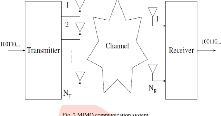
In multiple-input multiple-output (MIMO) communications, the system is equipped with multiple antennas at both the transmitter and the receiver technique. The multiple antenna schemes give a more reliable performance through array gain, diversity and spatial multiplexing. These concepts are briefly discussed below.
Fig. 2 MIMO communication system
The growing demand of multimedia services and the progress of Internet related contents lead to increasing interest to high speed communications network. The requirement for flexibility and wide bandwidth imposes the use of efficient transmission systems that would fit to the characteristics of wideband channels especially in wireless environment where the channel is very
challenging process. The fading of the signal can be mitigated by different diversity methods. To obtain diversity, in signal is transmitted through multiple independent fading paths in time, frequency or space and combined constructively at the receiver. III. FORWARD ERROR CORRECTING CODE
Claude Shannon created a mathematical foundation for the concept of channel capacity in 1948. By introducing channel capacity as a limit, he implied that instead of building a very good channel, one can achieve a desirable bit error rate by employing error-control codes.
Reed Solomon codes
Reed Solomon codes [1] are systematic linear block codes and are an important sub class of non binary BCH codes. RS codes operate on the information by dividing the message stream into blocks of data, adding redundancy per block depending only on the current inputs. The symbols in RS coding are elements of a finite field or Galois Field (GF). GF arithmetic is used for encoding and decoding of reed Solomon codes. GF multipliers are used for encoding the information block. The multiplier coefficients are the coefficients of the RS generator polynomial. Encoding is achieved by affixing the remainder of a GF polynomial division into the message. This division is accomplished by a Linear Feedback Shift Register (LFSR) implementation.
The RS encoder provided at the transmitter end encodes the input message into a codeword and transmits the same through the channel. Noise and other disturbances in the channel may disrupt and corrupt the codeword. This corrupted codeword arrives at the receiver end (decoder), where it gets checked and corrected message is passed on to the receiver.
Where, g(x) is the generator polynomial of degree 2t and given by
g(x) = (x+ ) (x+ )…… (x+ ) (x+ ) (2)
At the decoder, the syndrome of the received codeword is calculated using the generator polynomial to detect errors. Then to correct these errors, an error locator polynomial is calculated. From the error locator polynomial, the location of the error and its magnitude is obtained. Consequently a correct codeword is obtained.
Convolution code
As any binary code, convolutional codes protect information by adding redundant bits. A rate-k/n convolutional encoder processes the input sequence of k-bit information symbols through one or more binary shift registers (possibly employing feedback). The convolutional encoder computes each n-bit symbol (n > k) of the output sequence from linear operations on the current input symbol and the contents of the shift register(s). Thus, a rate k/n convolutional encoder processes a k-bit input symbol and computes an n-bit output symbol with every shift register update.
IJEDR1601055
International Journal of Engineering Development and Research (www.ijedr.org)351
decision decoding, where we are given a sequence of digitized parity bits, the branch metric is the Hamming distance between the expected parity bits and the received ones.IV. ZERO FORCING EQUALIZER
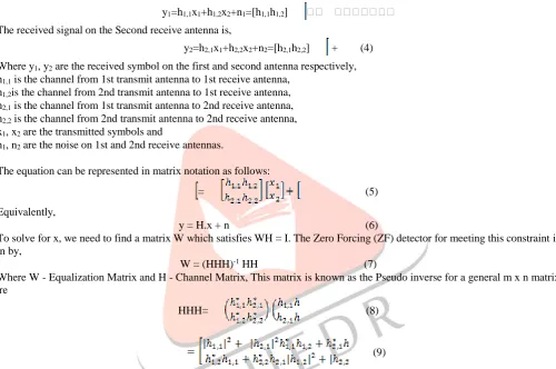
Zero Forcing Equalizer is a linear equalization algorithm used in communication systems, which inverts the frequency response of the channel. This equalizer was first proposed by Robert Lucky. The Zero-Forcing Equalizer applies the inverse of the channel to the received signal, to restore the signal before the channel. The name Zero Forcing corresponds to bringing down the ISI to zero in a noise free case. This will be useful when ISI is significant compared to noise. For a channel with frequency response F(f) the zero forcing equalizer C(f) is constructed such that C(f) = 1 / F(f). Thus the combination of channel and equalizer gives a flat frequency response and linear phase F(f)C(f) = 1.If the channel response for a particular channel is H(s) then the input signal is multiplied by the reciprocal of this. This is intended to remove the effect of channel from the received signal, in particular the Inter-symbol Interference (ISI). For simplicity let us consider a 2x2 MIMO channel, the channel is modeled as,
The received signal on the first receive antenna is,
y1=h1,1x1+h1,2x2+n1=[h1,1h1,2]
The received signal on the Second receive antenna is,
y2=h2,1x1+h2,2x2+n2=[h2,1h2,2] + (4)
Where y1, y2 are the received symbol on the first and second antenna respectively,
h1,1 is the channel from 1st transmit antenna to 1st receive antenna,
h1,2is the channel from 2nd transmit antenna to 1st receive antenna,
h2,1 is the channel from 1st transmit antenna to 2nd receive antenna,
h2,2 is the channel from 2nd transmit antenna to 2nd receive antenna,
x1, x2 are the transmitted symbols and
n1, n2 are the noise on 1st and 2nd receive antennas.
The equation can be represented in matrix notation as follows:
= (5)
Equivalently,
y = H.x + n (6)
To solve for x, we need to find a matrix W which satisfies WH = I. The Zero Forcing (ZF) detector for meeting this constraint is given by,
W = (HHH)-1 HH (7)
Where W - Equalization Matrix and H - Channel Matrix, This matrix is known as the Pseudo inverse for a general m x n matrix where
HHH= (8)
(9)
Note that the off diagonal elements in the matrix HHH are not zero, because the off diagonal elements are non zero in values. Zero forcing equalizer tries to null out the interfering terms when performing the equalization, i.e. when solving for x1 the
interference from x2 is tried to be nulled and vice versa. While doing so, there can be an amplification of noise. Hence the Zero
forcing equalizer is not the best possible equalizer. However, it is simple and reasonably easy to implement.
V. RESULT
Table 1 The WiMax system are simulated with the following parameters
S. No. Parameter Specification
1 FFT size 256
2 Cyclic Prefix 1/2
3 FEC code RS ,CC
4 Channel AWGN ,
5 Modulation technique BPSK,QPSK,QAM8
IJEDR1601055
International Journal of Engineering Development and Research (www.ijedr.org)352
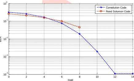
Fig. 3 Transmit image over WIMAX-MIMO process0 2 4 6 8 10 12 14
10-4
10-3
10-2
10-1
100
SNR
BER
Convolution Code Reed Solomon Code
IJEDR1601055
International Journal of Engineering Development and Research (www.ijedr.org)353
0 2 4 6 8 10 12 14 16 18
0 10 20 30 40 50 60 70 80 90
SNR
R
M
S
E
Convolution Code Reed solomon code
Fig. 5 Performance of RMSE to SNR
0 2 4 6 8 10 12 14 16 18
5 10 15 20 25 30 35 40 45 50
SNR
P
S
N
R
Convolution Code Reed Solomon Code
Fig. 6 Performance of RMSE to SNR Table 2 Performance FEC code
S.No. SNR CC RS CC RS CC RS
BER PSNR RMSE
1 0 0.3248 0.2617 9.579 12.85 84.64 58.09
2 4 0.1718 0.1565 12.53 15.43 60.25 43.13
3 8 0.0193 0.0449 22.42 20.18 19.31 24.99
IJEDR1601055
International Journal of Engineering Development and Research (www.ijedr.org)354
CONCLUSIONThe simulation results shows that the use of MIMO-WiMAX system gives better performance for image transmission. The MIMO technique is also used here with the 2 x 1 antenna system for BER performance improvement. In this paper WiMAX system is used for image transmission, zero forcing method and FEC code is used for improving. A comparison is made between the diversity gain of MIMO systems in terms of BER for High QAM modulation scheme. The simulation results also show that the image can be recovered at the receiver even at very low SNR values. It is found that with increase of modulation order the capacity enhancement but BER are degraded, the can be recovering with the increase in number of receiver antennas.
REFERENCES
[1] Bit Error Rate Performance in OFDM System Using MMSE & MLSE Equalizer Over Rayleigh Fading Channel Through The BPSK, QPSK,4 QAM & 16 QAM Modulation Technique, Vol. 1, Issue 3, pp.1005-1011.
[2] Capacity and performance analysis of space-time block coded MIMO-OFDM systems over Rician fading channel by Imran Khan, Shujaat Ali Khan Tanoli, and Nandana Rajatheva, 2009.
[3] Performance Analysis of MIMO-OFDM for 4G Wireless Systems under Rayleigh Fading Channel, International Journal of Multimedia and Ubiquitous Engineering Vol. 8, No. 1, January, 2013.
![Fig. 1 Wireless communication system [8]](https://thumb-us.123doks.com/thumbv2/123dok_us/8253007.1374921/1.595.103.502.471.682/fig-wireless-communication-system.webp)