Real-Time Hand Gesture Controlled Advanced Security
System for Robotic Vehicle
Jalli Raj Kumar & Bujja Ramesh Reddy
1
B.Tech, M.tech scholar ,
2, Professor M.tech(ph.D)
1,2
LakiReddy Bali Reddy College of Engineering, Mylavaram(v), Krishna (D),A.P
Email:
1[email protected]
,
2[email protected]
ABSTRACT: Distracted driving is one of the main
causes of vehicle collisions in the United States.
Passively monitoring a driver’s activities constitutes
the basis of an automobile safety system that can
potentially reduce the number of accidents by
estimating the driver’s focus of attention. This paper
proposes an inexpensive vision-based system to
accurately detect Eyes Off the Road (EOR). The
system has three main components: 1) robust facial
feature tracking; 2) head pose and gaze estimation;
and 3) 3-D geometric reasoning to detect EOR.
Gesture Controlled Car is a robot which can be
controlled by simple human gestures. The user just
needs to wear a gesture device in which a sensor is
included. The sensor will record the movement of
hand in a specific direction which will result in the
motion of the robot in the respective directions. The
robot and the Gesture instrument are connected
wirelessly through radio waves. User can interact
with the robot in a more friendly way due to the
wireless communication. It will allow user to control
the forward, backward, leftward and rightward
movements, while using the same sensor to control
the throttle of the car. Movement of car is controlled
by the differential mechanism. The mechanism
involves the rotation of both forth & rear wheels of
left or right side to move in the Anticlockwise
direction and the other pair to rotate in the clockwise
direction which makes the car to rotate about its own
axis without any kind of forward or backward
motion. The main advantage of this mechanism is the
car with this mechanism can take sharp turn without
any difficulty.
Keywords:MEMS,GSM,GPS,Zigbee.
INTRODUCTION
Driver distractions are the leading cause of most
vehicle Crashes and near-crashes. According to a
study Released by the national highway traffic safety
administration and the Virginia tech transportation
institute [6], 80% of crashes and 65% of near-crashes
involve some form of driver distraction. In addition,
distractions typically occurred within three seconds
before the vehicle crash. Recent reports have shown
that from 2011 to 2012, the number of people injured
in vehicle crashes related to distract driving has
increased 9% [1]. In 2012 alone, 3328 people were
killed due to distracted driving crashes, which is a
slight reduction from the 3360 in 2011. Distracted
driving is defined as any activity that could divert A
person’s attention away from the primary task of
driving. Distractions include texting, using a smart
phone, eating and drinking, adjusting a CD player,
operating a gps system or Talking to passengers. This
is particularly challenging nowadays, where a wide
Spectrum of technologies have been introduced into
the car Environment. A Gesture Controlled robot is a
kind of robot which can be controlled by hand
buttons. The user just needs to wear a small
transmitting device on his hand which includes a
sensor. Movement of the hand in a specific direction
will transmit a command to the robot which will then
move in a specific direction. At the receiving end an
RF Receiver module will receive the encoded data
and decode it by using a decoder IC. This data is then
processed by a microcontroller and passed onto a
motor driver to rotate the motors in a special
configuration to make the robot move in the same
direction as that of the hand.
METHODOLOGY
In this project, it was having two methods used for
two sections. Whereas, firstly we consider the
transmitter section and then receiver section.
TRANSMITTER SECTION:
Fig 1: Block diagram
In this transmitter section, considering a
wireless remote which was respective of the
car is used.
After dismantle the remote, using only the
transmitter circuit which consists of RF
module along with 4 tap buttons.
As per the project, developing this wireless
remote car to gesture control using a micro
controller.
Micro controller
This section forms the control unit of the whole
project. This section basically consists of a
Microcontroller with its associated circuitry like
Crystal with capacitors, Reset circuitry, Pull up
resistors (if needed) and so on. The Microcontroller
forms the heart of the project because it controls the
devices being interfaced and communicates with the
devices according to the program being written.
Fig 2: Micro controller
MEMS:
Micro-Electro-Mechanical Systems (MEMS) is the
integration of mechanical elements, sensors,
actuators, and electronics on a common silicon
substrate through micro fabrication technology.
Microelectronic integrated circuits can be thought of
as the "brains" of a system and MEMS augments this
decision-making capability with "eyes" and "arms",
to allow micro systems to sense and control the
environment. Sensors gather information from the
environment through measuring mechanical, thermal,
biological, chemical, optical, and magnetic
phenomena. The electronics then process the
information derived from the sensors and through
to respond by moving, positioning, regulating,
pumping, and filtering, thereby controlling the
environment for some desired outcome or purpose.
Because MEMS devices are manufactured using
batch fabrication techniques similar to those used for
integrated circuits, unprecedented levels of
functionality, reliability, and sophistication can be
placed on a small silicon chip at a relatively low cost.
Fig 3: MEMS IC
Fig 3.1:MEMS hand directions
RECEIVING SECTION:
Fig 4: Block diagram
HARDWARE SYSTEM
We can overcome the disadvantage of the existing
method by improving system prototype is built on the
base of one embedded platform ARM which controls
all the processes. Experimental results illuminate the
validity of this car security system. In this proposed
embedded car security system, IRS (Iris recognition
System) is used to detect the iris of the driver and
compare it with the predefined iris. For example, in
the night when the car’s owner is sleeping and
someone theft the car then IRS obtains images by one
tiny web camera which can be hidden in the car. IRS
compares the obtained image with the predefined
images if the image doesn’t match, then the
information is sent to the owner through SMS. So
now owner can obtain the alert of the thief in his
mobile as well as.
ARM7TDMI: ARM is the abbreviation of Advanced
RISC Machines, it is the name of a class of
The RISC instruction set, and related decode
mechanism are much simpler than those of Complex
Instruction Set Computer (CISC) designs.
Fig 5:ARM7
Liquid-crystal display (LCD) is a flat panel display,
electronic visual display that uses the light
modulation properties of liquid crystals. Liquid
crystals do not emit light directly. LCDs are available
to display arbitrary images or fixed images which can
be displayed or hidden, such as preset words, digits,
and 7-segment displays as in a digital clock.
GSM:
Global System for Mobile Communication (GSM) is
a set of ETSI standards specifying the infrastructure
for a digital cellular service.
Fig 7:gsm
The network is structured into a number of discrete
sections:
Base Station Subsystem – the base stations
and their controllers explained
Network and Switching Subsystem – the
part of the network most similar to a fixed
network, sometimes just called the "core
network"
GPRS Core Network – the optional part
which allows packet-based Internet
connections
Operations support system (OSS) – network
maintenance
SMS was intended to be a secure wireless
system. It has considered the user
authentication using a pre-shared key and
challenge-response, and over-the-air
encryption. However, GSM is vulnerable to
different class of attacks, each of them
aiming a different part of the network.
Fig 7 .1:GSM architecture
A buzzer or beeper is a signaling device, usually
electronic, typically used in automobiles, household
appliances such as a microwave ovens, & game
shows. The word "buzzer" comes from the rasping
noise that buzzers made when they were
electromechanical devices, operated from
stepped-down AC line voltage at 50 or 60 cycles. Other
sounds commonly used to indicate that a button has
been pressed are a ring or a beep.
A car alarm is an electronic device installed in
a vehicle in an attempt to discourage theft of the
vehicle itself, its contents, or both. Car alarms work
by emitting high-volume sound (often a
vehicle-mounted siren, klaxon, pre-recorded verbal warning,
the vehicle's own horn, or a combination of these)
when the conditions necessary for triggering it are
met. Such alarms may also cause the vehicle's
headlights to flash, may notify the car's owner of the
incident via a paging system, and may interrupt one
or more electrical circuits necessary for the car to
start. Although inexpensive to acquire and install, the
effectiveness of such devices in deterring vehicle
burglary or theft when their only effect is to emit
sound appears to be negligible.
Fig 8: Types of Buzzers
Eye Blink sensor:
This project involves measure and controls the eye
blink using IR sensor. The IR transmitter is used to
transmit the infrared rays in our eye. The IR receiver
is used to receive the reflected infrared rays of eye. If
the eye is closed means the output of IR receiver is
high otherwise the IR receiver output is low. This to
know the eye is closing or opening position. This
output is give to logic circuit to indicate the alarm.
This project helps in controlling accidents due to
unconsciousness through Eye blink. Here one eye
blink sensor is fixed in vehicle where if driver looses
consciousness, then it is indicate through alarm.
Fig 9: Eye blink sensor
Alcohol sensor:
Sensitive material of MQ-3 gas sensor is SnO2,
which with lower conductivity in clean air. When the
target alcohol gas exist, the sensor’s conductivity is
higher along with the gas concentration rising. Please
use simple electro circuit, Convert change of
conductivity to correspond output signal of gas
concentration. MQ-3 gas sensor has high sensitivity
to Alcohol, and has good resistance to disturb of
gasoline, smoke and vapor. The sensor could be used
to detect alcohol with different concentration; it is
Fig 10: Alcohol sensor
Ultrasonic sensor:
The sensor is primarily intended to be used in
security systems for detection of moving objects, but
can be effectively involved in intelligent children’s
toys, automatic door opening devices, and sports
training and contact-less-speed measurement
equipment. Infrared sensors are characterized by high
sensitivity, low cost and are widely used. But, these
sensors can generate false alarm signals if heating
systems are active or temperature change speed
exceeds some threshold level. Moreover, infrared
sensors appreciably lose sensitivity if small insects
penetrate the sensor lens. Ultrasound motion
detection sensors are characterized by small power
consumption, suitable cost and high sensitivity. That
it why this kind of sensor is commonly used in home,
office and car security systems. Existing ultrasound
sensors consist of multiple passive and active
components and are relatively complicated for
production and testing. Sensors often times require a
laborious tuning process.
Fig 11: Ultrasonic sensor
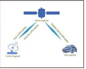
GPS:
Global Positioning System (GPS) technology
is changing the way we work and play. You can use
GPS technology when you are driving, flying, fishing,
sailing, hiking, running, biking, working, or
exploring. With a GPS receiver, you have an amazing
amount of information at your fingertips. Here are just
a few examples of how you can use GPS technology.
Fig 12:gps
SIM908 module identify your phone number
when you call it and if it is correct, the GPS
fixes the GPS satellites. The GPRS+GPS
shield will connect to the network and will
send the GPS data throught HTTP request.
Then we can show the position of the device
in Google Maps. It's very simple: a GPS
module to get position data and the 3G
the coordinates of the car. It starts to send
the HTTP request every few seconds with
data of the position (latitude and longitude).
Fig 12.1: GPS Working
ZIGBEE:
Zigbee modules feature a UART interface, which
allows any microcontroller or microprocessor to
immediately use the services of the Zigbee protocol.
All a Zigbee hardware designer has to do in this case
is ensure that the host’s serial port logic levels are
compatible with the XBee’s 2.8- to 3.4-V logic
levels. The logic level conversion can be performed
using either a standard RS-232 IC or logic level
translators such as the 74LVTH125 when the host is
directly connected to the XBee UART. The X- Bee
RF Modules interface to a host device through a
logic-level asynchronous Serial port. Through its
serial port, the module can communicate with any
logic and voltage Compatible UART; or through a
level translator to any serial device.
Data is presented to the X-Bee module through its
DIN pin, and it must be in the asynchronous serial
format, which consists of a start bit, 8 data bits, and a
stop bit. Because the input data goes directly into the
input of a UART within the X-Bee module, no bit
inversions are necessary within the asynchronous
serial data stream. All of the required timing and
parity checking is automatically taken care of by the
X-Bee’s UART.
Fig 13: ZIGBEE pin diagram
DC Motor:
Fig 14: DC Motor
A DC motor relies on the fact that like magnet poles
repels and unlike magnetic poles attracts each other.
A coil of wire with a current running through it
generates an electromagnetic field aligned with the
center of the coil. By switching the current on or off
in a coil its magnetic field can be switched on or off
the direction of the generated magnetic field can be
switched 180°.
Motor driver (L293D):
DC motors are typically controlled by using a
transistor configuration called an "H-bridge". This
consists of a minimum of four mechanical or
solid-state switches, such as two NPN and two PNP
transistors. One NPN and one PNP transistor are
activated at a time. Both NPN and PNP transistors
can be activated to cause a short across the motor
terminals, which can be useful for slowing down the
motor from the back EMF it creates. H-bridge.
Sometimes called a "full bridge" the H-bridge is so
named because it has four switching elements at the
"corners" of the H and the motor forms the cross bar.
The switches are turned on in pairs, either high left
and lower right, or lower left and high right, but
never both switches on the same "side" of the bridge.
If both switches on one side of a bridge are turned on
it creates a short circuit between the battery plus and
battery minus terminals. If the bridge is sufficiently
powerful it will absorb that load and your batteries
will simply drain quickly. Usually however the
switches in question melt.
RESULTS
Fig 15:Foward Gesture
The figure shown above represents the car moving
when the hand is tilted downwards.
That is, since the gesture is down, the movement is
forward.
Fig 16:Left Gesture
The figure shown above represents the car turning
towards left and the lights are indicated when the hand is tilted towards left. That is, since the gesture is
left, the movement is sideways (left).
Fig 17:Right Gesture
The figure shown above represents the car turning
hand is tilted towards right. That is, since the gesture
is right, the movement is
sideways (right).
Fig 18: Backward Gesture
The figure shown above represents the car moving
when the hand is tilted backwards.
That is, since the gesture is down, the movement is
backward.
CONCLUSION
The goal of the system is to detect eye gaze direction
and head pose direction to detect if eyes off the road.
Another goal is to detect drowsiness condition of
driver and alert driver in both conditions. Viola Jones
algorithm is implemented in Open CV for rapid face
detection with eyes extraction. Real time eye gaze
tracking is proposed with CAMSHIFT algorithm.
Pupil tracking is achieved Head pose estimation is
proposed with ARM and POSIT. Different gaze
zones are defined and eyes off the road can
be detected by combining eye gaze and head position.
Fatigue detection can be achieved by detecting closed
eyes. If driver eyes are off the road or if he is drowsy
then alert will be generated. System is robust as two
methods are combined to find gaze. If one method is
failed to detect properly, other will work. System is
also robust under night or low light conditions due to
use of IR illuminators and build on raspberry pi to be
compact and low cost. Future work can include
improving driver monitoring system with help of
automatic calibration, determining
vehicle states, weather conditions, vehicle speed etc.
REFERENCES
[1] Chan Wah NG, Surendra Ranganath, Real-time
Gesture Recognition System and Application Image
And Vision Computing (20): 993-1007,2002.
[2] Sergios Theodoridis, Konstantinos Koutroumbas,
Pattern Recognition, esevier Publication, Second
Edition,2003.
[3] Seyed Eghbal Ghobadi, Omar Edmond
Loepprich, Farid Ahmadov Jens Bernshausen,Real
Time Hand Based Robot Control Using Multimodal
Images, Iaengm International Journal Of Computer
Science, 35:4, IJCS_35_4_08, nov2008.
[4] Aswath S, Chinmaya Krishna Tilak, Amal Suresh
and Ganesha Udupa, “Human Gesture Recognition
for Real-Time Control of Humanoid Robot”,
International Journal ofAdvances in Mechanical and
Automobile Engineering (IJAMAE), Vol- 1, Issue 1,
PP.96-100, (2014).
[5] Shruthi B. N, Shivraj, Sumathi S, “Hand Gesture
Based Direction Control of Robocar using Arduino
Microcontroller”, International Journal of Recent
Technology and Engineering(IJRTE), Volume-3,
Issue-3, PP.-32-35, July2014.
[6] Vicky Somkuwar, Roshan Gabhane, Sandeep
Gesture Controlled Robot using Flex sensor and
Accelerometer”.
[7] C. Ahlstrom, K. Kircher, and A. Kircher, “A
gaze-based driver distraction warning system and its
effect on visual behavior,” IEEE Trans. Intell.
Transp. Syst., vol. 14, no. 2, pp. 965–973, Jun. 2013.
[8] A. Nabo, “Driver attention—Dealing with
drowsiness and distraction,” Smart Eye, Gothenburg,
Sweden, Tech. Rep., 2009.
[9] J. P. Batista, “A real-time driver visual attention
monitoring system,” in Pattern Recognition and
Image Analysis, vol. 3522, Berlin, Germany:
Springer-Verlag, 2005, pp. 200–208.
[10] L. M. Bergasa, J. Nuevo, M. A. Sotelo, R.
Barea, and M. E. Lopez, “Realtime system for monitoring driver vigilance,” IEEE Trans. Intell.
Transp. Syst., vol. 7, no. 1, pp. 63–77, Mar. 2006.
AUTHORS DETAILS
STUDENT DETAILS :
Name : Jalli Raj Kumar
Jalli Raj Kumar Receivedthe B.Tech in Electronics &
Communication Engineering from JNTUK Kakinada
in 2016 and Pursuing M. Tech in VLSI &
EMBEDDED SYSTEMS from Lakireddy Bali
Reddy College of Engineering, Mylavaram.
FACULTY DETAILS:
Name: Bujja Ramesh Reddy
Bojja Ramesh Reddy Received the B.Tech in
Electronics & Communications Engineering from
NBKRIST Nellore in 1995 and M.E in UVCE from
Bangalore in 2002. PhD pursuing at JNTUH college
of Engineering. His are as of interest is SIGNAL
PROCESSING. Presently he is working as a
Professor &HoD, Department of Electronics and
Communication Engineering, LakiReddy Bali Reddy