DEFINITY
®
Communications
System
Generic 3 Installation
(For Single-Carrier Cabinets)
Contents
Table of Contents
iAbout This Book
xv■ This Book’s Organization xv
■ Other Books xvi
■ Trademarks xvii
1
Overview and Roadmap
1-1■ System Reliability 1-1
Standard Reliability 1-2
High Reliability 1-2
Critical Reliability 1-2
■ DEFINITY System Installation Roadmap 1-3
Plan and Prepare the Site 1-3
Unpack the Cabinets 1-3
Install and Connect the Cabinets 1-3 Install Telecommunications Cabling 1-4 Install Generic 3 Management Terminal (G3-MT) 1-4
Activate the System 1-5
Test the System 1-5
Install and Wire Telephones and Other
Equipment 1-6
Administer the DEFINITY System According to
Customer Requirements 1-7
Test Telephones and Other Equipment 1-7
2
Plan and Prepare the Site
2-1■ Check the Customer’s Order 2-1
Generic 3 Management Terminal
(G3-MT) Requirements 2-2
Cross-Connect Fields 2-2
Space Requirements 2-2
Room Layout 2-2
Figure Notes: 2-3
Cable Slack Manager (Optional) Requirements 2-4
Tools Needed 2-4
Lay Out and Ensure Ap propriate Power 2-6 Power Arrangements for AC Power 2-6 Power Arrangements for DC Power 2-7
■ Lay Out and Ensure Appropriate Grounding 2-8
Connect Coupled Bonding Conductor 2-8
■ Determine the Location of the Equipment Closets 2-9 ■ Determine External Trunk Locations 2-9
■ Create a Provisioning Plan 2-9
3
Unpack the Cabinet
3-1Unpack and Inspect for Damage 3-1
4
Install and Connect the Cabinets
4-1■ Install Earthquake Mounting 4-2
■ Position and Stack the Cabinets 4-2 ■ Connect System Cabinet Grounds 4-3
Figure Notes: 4-4
■ Connect Battery Leads 4-5
■ Connect Power 4-6
Connect AC Power 4-6
Connect DC Power 4-6
Figure Notes: 4-8
Connect Power Plant Ground 4-9
Figure Notes: 4-9
Connect Frame Ground 4-10
Figure Notes: 4-10
Contents
Figure Notes: 4-11
Connect Single-Carrier Network Grounding 4-11
Figure Notes: 4-12
Coupled Bonding Conductor (CBC) 4-12
Figure Notes: 4-13
Connect DC Power to Networks 4-14 Connect AC Power to DC Power Cabinet 4-14
Test DC Power Plant 4-14
Connect Stand-by Power 4-14
■ Locate and Connect Time Division
Multiplexing (TDM) Bus 4-15
Figure Notes: 4-16
■ Locate and Connect Inter-Cabinet Cables (ICC) 4-17
Figure Notes: 4-18
■ Install Fibre-Optic Cables 4-19
Fibre-Optic Cable Operation 4-19
Locate Fibre-Optic Cable Connections 4-19 General Rules and Recommendations for
Connecting Fibre-Optic Cables 4-20
Figure Notes: 4-22
Figure Notes: 4-23
Raised Floor or Cable Slack Managers 4-23
Cable Connections 4-24
Standard Reliability Fibre-Optic Cable Connections 4-25 High Reliability Fibre-Optic Cable Connections 4-26 Critical Reliability Fibre-Optic Cable Connections 4-27
■ Verify Port Cabinet Address Plugs 4-29
■ Install Back Panels 4-30
■ Install Ground Plates 4-30
Figure Notes: 4-30
Install Ground Plates on Systems with
Earthquake Protection 4-31
Install Ground Plates on Systems without
Earthquake Protection 4-31
Figure Notes: 4-31
■ Install Cable Clamps 4-34
Figure Notes: 4-34
Install Front Plates on Systems with
Earthquake Protection 4-35
Install Cabinet Clip On Systems without
Earthquake Protection 4-35
Figure Notes: 4-36
5
Install Telecommunications Cabling
5-1■ Install the Cross-Connect Field 5-1
Typical Cross-Connect Field Using
110-Type Hardware 5-1
Figure Notes: 5-2
Hardware Installation 5-3
■ Install Cable Slack Managers 5-3
■ Route Cables from Cabinet to Cross-Connect Field 5-3
Figure Notes: 5-5
Figure Notes: 5-6
■ Connect Control Carrier Outputs Cable 5-6
Label Cables 5-7
■ Install Trunk Cables Among Network
Interface, Sneak Current Protector, and
Switch Cabinet 5-7
6
Install Generic 3 Management Terminal
6-1■ Generic 3 Management Terminal
(G3-MT) Requirements 6-1
■ Connect Generic 3 Management Terminal (G3-MT) 6-2
Figure Notes: 6-4
■ Set Up G3 Management Terminal (G3-MT) 6-6 ■ Remotely Connect Generic 3
Management Terminal (G3-MT) 6-7
Figure Notes: 6-7
7
Activate the System
7-1■ Power Up Switch 7-2
Contents
Power up AC-Powered Switch 7-3
Power up DC-Powered Switch 7-3
Verify Messages on Terminal 7-3
■ Introduction to Terminal Screens and Commands 7-4
Screens 7-4
Commands 7-5
Getting Help 7-5
■ Log in to the System 7-5
■ Set Required Country Options 7-6
■ Change Craft Password 7-9
■ Set Date and Time 7-11
■ Set System Maintenance Parameters 7-14
■ Save Translations 7-15
Logoff 7-17
8
Test the System
8-1■ Check the System Status for Each Cabinet 8-1 ■ Check Circuit Pack Configuration 8-4 ■ Test Time Division Multiplexor (TDM)
Bus in Processor Port Network (PPN) 8-9
■ Test Tone-Clock Boards 8-10
■ Test Switch Processing Element (SPE)
Duplication Memory Shadowing Link 8-11
■ Test Duplicated Switch Processing
Element (SPE) Interchange 8-12
■ Test Expansion Interface Boards 8-14 ■ Test Time Division Multiplexer (TDM)
for each Expansion Port Network (EPN) 8-15
■ Test Tone-Clock for each Expansion
Port Network (EPN) 8-16
■ Test Tone-Clock Interchange for each
Expansion Port Network (EPN) 8-17
■ Test Expansion Interface Exchange for
Each Expansion Port Network (EPN) 8-17
Re-install Front Doors 8-20
■ Next Steps 8-20
9
Install and Wire Telephones and
Other Equipment
9-1■ Telephone Connection Example 9-1
Connect Adjunct Power 9-3
■ Analog Station or 2-Wire Digital Station Example 9-5
■ Analog Tie Trunk Example 9-6
■ Digital Tie Trunk Example 9-9
■ Auxiliary Connector Outputs 9-10
■ APP Connector and Cable Diagrams (Pinout Charts) 9-15 ■ Install Initialization and Administration System (INADS)
Interface 9-21
Figure Notes: 9-21
Figure Notes: 9-22
■ Install Emergency Transfer Units and
Associated Telephones 9-23
Install the 808A Emergency Transfer Panel 9-23
■ Install External Ringing 9-24
Requirements 9-24
Installation 9-24
Figure Notes: 9-25
■ Install Queue Warning Indicator 9-25
Requirements 9-25
Installation 9-26
■ Install the 1145B1 Power Supply 9-26
Wall-Mounting Plates 9-27
Figure Notes: 9-28
Mount the 1145B1 Power Supply 9-29
Figure Notes: 9-29
Mount the 1146B1 Power Distribution Unit 9-30
Battery Mounting/Wiring 9-30
Power Up and Test 9-31
Contents
Figure Notes: 9-32
Reset Light Emitting Diodes (LED) on Power Distribution
Unit 9-33
■ Install the MSP-1 Power Supply 9-34
Underwriter’s Laboratories (UL) Information 9-34 Important Safety Instructions 9-35 Description of the MSP-1 Power Supply 9-36 Locate the MSP-1 Power Supply 9-36 Mount the MSP-1 Power Supply 9-36
Connect the Power Supply 9-37
Figure Notes: 9-38
Figure Notes: 9-39
■ Install the Basic Rate Interface (BRI)
Terminating Resistor 9-39
Terminating Resistor Adapter 9-40
Closet Mounted (110RA1-12) 9-41
Figure Notes: 9-41
Figure Notes: 9-42
■ Install Multipoint Adapters 9-42
BR851-B Adapter (T-Adapter) 9-43
367A Adapter 9-44
Basic Multipoint Installation Distances 9-45
Figure Notes: 9-46
■ Install Power Adapters 9-47
400B2 9-47
400F2 9-48
■ Install Auxiliary Equipment 9-49
Auxiliary Equipment Description 9-49 Install Loudspeaker Paging and Music-on-Hold 9-50 Install Loudspeaker Paging Access without
Paging Adapter 9-50
Requirements 9-50
Figure Notes: 9-51
Install Loudspeaker Paging Access 9-51 Install Music-on-Hold Access 9-52
Requirements 9-52
Install Federal Communications Commission
(FCC) Registered Music Source 9-54 Install Recorded Announcement Equipment 9-54
Requirements 9-54
Figure Notes: 9-55
■ Install Processor Data Modules (PDMs) 9-55
Requirements 9-55
Installation 9-56
Figure Notes: 9-57
Connection to Individual Processor Data Modules
(PDMs) 9-57
Figure Notes: 9-58
■ Install Call Management System (CMS) Interface 9-58
Figure Notes: 9-59
■ Install Property Management System (PMS) Interface 9-59
Requirements 9-59
Figure Notes: 9-61
■ Install Customer-Provided Terminal
Using Asynchronous Data Unit (ADU) 9-61
Requirements 9-61
Installation 9-61
■ Install Station Message Detail
Recording (SMDR)/Call Detail
Recording Unit (CDRU) Interface 9-62 Interface Cabling to Station Message Detail
Recording (SMDR) Output Device 9-63
Figure Notes: 9-64
Switch Settings for Processor Data Module (PDM), Trunk Data Module (TDM), or 212-Type
Modem 9-65
212-Type Modem Switch Setting 9-66
■ Implement and Administer System Data 9-66
10
Test Telephones and Other Equipment
10-1■ Make Test Calls (Single-Cabinet Switch) 10-2
Description 10-2
Procedure 10-2
Contents
Description 10-3
Procedure 10-3
■ Make Test Calls (Three-Cabinet Switch) 10-4
Description 10-4
Procedure 10-5
■ Test the Attendant Console 10-8
Description 10-8
Procedure 10-8
■ Test the Selector Console 10-9
Description 10-9
Procedure 10-9
■ Test External Ringing 10-9
Description 10-9
Procedure—Ringing Device Installed 10-9 Procedure—Ringing Device Not Installed 10-10
■ Test Queue Warning Indicator 10-10
Description 10-10
Procedure—Queue Warning Indicator Installed 10-10 Procedure—Queue Warning Indicator Not
Installed 10-11
■ Test Integrated Announcement 10-12
Description 10-12
Procedure — Record Announcement 10-12 Procedure — Playback Announcement 10-12 Procedure —Delete Announcement 10-12
■ Test Music-on-Hold 10-13
Description 10-13
Procedure 10-13
■ Test Emergency Transfer 10-13
Description 10-13
Procedure 10-14
■ Test Remote Access Interface (known
as Initialization and Administration
System) 10-14
Description 10-14
Procedure—Local Test 10-15
■ Test Basic Rate Interface (BRI) 10-15
Description 10-15
Procedure—Dial Tone 10-15
Procedure—Make and Receive Calls 10-15 Procedure—Checking the Service Profile
Identifier (SPID) 10-16
A
Approved Grounds
A-1■ Definition of Ap proved Ground A-1 ■ Acceptable Mediums for Protective Ground A-1
■ Approved Floor Grounds A-2
B
Earthquake Protection Procedures
B-1■ Install Floor Mounting to Attach Cabinet to Floor B-1
Figure Notes: B-2
Figure Notes: B-3
■ Install Ground Plates on Cabinet Backs B-4
■ Install Front Plates B-4
C
DEFINITY AUDIX System Power Procedures
C-1■ Manually Power Down DEFINITY AUDIX System C-1 ■ Manual Power Up DEFINITY AUDIX System C-3
D
Country Differences
D-1■ United States to United Kingdom and
France Terminology Translations D-1
■ Country-Specific Hardware D-1
E
Installing the 9400-Series Telephones
E-1■ Installing the 9400-Series Telephones E-1
Contents
Distance Limitations E-4
Figure Notes: E-5
Figure Notes: E-5
■ Wall Mounting E-6
■ Using the Test Feature E-9
The Test Feature E-9
■ Button Labels E-10
F
Wire Conversion Information
F-1■ Common Wire Colours F-1
■ AWG to SWG Conversion
(Stranded Wire) F-1
■ Wire Gauge Comparison
(Solid Conductor) F-4
G
Electrical Code Equivalencies
G-1■ North American Electrical Code G-1 ■ International Electrical Codes G-1
H
Option Switch Settings
H-1■ Distributed Communications System
(DCS) Option Settings for G3i Systems H-1
■ Modem Pooling (Combined) Option Settings H-2
■ 103JR Modem Option Settings H-2
■ 201CR Modem Option Settings H-4
■ 202SR Modem Option Settings H-6
■ 208BR Modem Option Settings H-9
■ Asynchronous 212AR Modem Option Settings H-11 ■ Synchronous 212AR Modem Option Settings H-14 ■ Asynchronous 2224A Modem Option Settings H-17 ■ Synchronous 2224A Modem Option Settings H-18
■ 7400A Option Settings H-19
■ Printer Option Settings H-20
475 Printer Used as System Printer H-21
■ 475 or 476 Printer Used as Journal
Printer for Hospitality Feature H-21
■ 470 or 471 Printer Used as Journal
Printer for Hospitality Feature H-28
■ 572 Printer H-30
■ Station Message Detail Recording
(SMDR) Interface Option Settings H-34
■ Audio Information Exchange (AUDIX)
Interface Option Settings for G3i Systems H-36
■ TN760 Tie Trunk Circuit Pack Option Settings H-37 ■ TN464C, D, E, F Option Settings H-41
TN464C/D Option Settings H-41
Figure Notes: H-42
TN464E/F Option Settings H-42
Figure Notes: H-44
I
References
I-1■ Basic I-1
■ Call Center I-5
■ Networks I-6
■ Application Specific I-7
ABB
Abbreviations
ABB-1About This Book
This book supports DEFINITY® Communications Systems Generic 3 Version 3 and later. This book provides procedures and information for installing the hardware and initially testing the DEFINITY Communications System Generic 3, Models G3i and G3s. The information in this book applies to single-carrier cabinet switches only.
DEFINITY is a registered trademark of AT&T. DEFINITY Communications System Generic 3 is abbreviated as G3.
This Book’s Organization
This book is organized into 10 chapters and 10 appendices. The procedures in this book should be read and followed sequentially.
■ Chapter 1, "Overview and Roadmap"
Provides an overview of system reliability options and a step-by-step roadmap for installing and testing the system.
■ Chapter 2, "Plan and Prepare the Site"
Explains how to plan and prepare the site and includes typical floor plans.
■ Chapter 3, "Unpack the Cabinet"
Explains how to safely unpack the cabinets.
■ Chapter 4, "Install and Connect the Cabinets"
Explains how to install cabling between the switch and the cross-connect field.
■ Chapter 6, "Install Generic 3 Management Terminal"
Explains how to install and bring up the Generic 3 Management Terminal.
■ Chapter 7, "Activate the System"
Explains how to activate and initialize the system.
■ Chapter 8, "Test the System"
Explains how to test the system.
■ Chapter 9, "Install and Wire Telephones and Other Equipment"
Explains how to install and wire telephones and other equipment to the switch.
■ Chapter 10, "Test Telephones and Other Equipment"
Explains how to test the equipment installed in Chapter 9.
■ Appendix A, "Approved Grounds"
■ Appendix B, "Earthquake Protection Procedures"
■ Appendix C, "DEFINITY AUDIX System Power Procedures"
■ Appendix D, "Country Differences"
■ Appendix E, "Installing the 9400-Series Telephones" ■ Appendix F, "Wire Conversion Information"
■ Appendix G, "Electrical Code Equivalencies" ■ Appendix H, "Option Switch Settings" ■ Appendix I, "References"
■ Abbreviations ■ Index
Other Books
In addition to this book, other system description, installation and test, maintenance, and administration books are available. A complete list of DEFINITY Generic 3 books available in United States English can be found in the
Global Business Communications Systems Publications Catalog, 555-000-010. A
Trademarks
This catalog and all DEFINITY Communications System Generic 3 documentation in United States English can be ordered directly from:
General Business Communications System Publications Fulfillment Centre at 1-317-361-5353.
Trademarks
This book contains references to the following trademarked products:
1
This chapter presents general information about the methods to configure your DEFINITY System Generic 3 for system availability.
It also provides a roadmap (a high-level overview of the sequence of steps) for the installation of the system. The roadmap provides references to the
appropriate chapter in this book or other books for detailed instructions.
System Reliability
The DEFINITY System G3 provides various system reliability configurations or duplication options. These reliability configurations provide for duplication of G3 system components for higher system availability. The following three types of reliability supply your system’s needs:
■ Standard Reliability ■ High Reliability ■ Critical Reliability
Within these configuration options, you can duplicate the following components:
■ Processor Port Network (PPN) Control Carrier ■ Expansion Port Network (EPN) Control Carrier
■ Inter-Port Network (PN) Connectivity (fibre-optic cabling) ■ Tone-Clock
Overview and Roadmap
Standard Reliability
DEFINITY System G3 standard reliability systems provide the most cost-effective product. This is the only reliability offering for a G3s system. Standard reliability systems do not duplicate Tone-Clock(s), the Control Carriers, or any inter-Port Network (PN) connectivity.
Standard reliability systems use the following components:
■ One control carrier per port network (Expansion Port Network (EPN) or
Processor Port Network (PPN))
■ One Tone-Clock per port network
■ Simplex inter-Port Network (PN) connectivity (via fibre-optic cables)
High Reliability
The G3i high reliability option provides duplication of hardware associated with the Processor Port Network (PPN) Control Carrier.
High Reliability systems use the following components:
■ Duplicate Control Carriers in the Processor Port Network (PPN) ■ Duplicate Processor Port Network (PPN) Tone-Clocks, one in each
Control Carrier
■ One Tone-Clock per Expansion Port Network (EPN) ■ Simplex inter-Port Network (PN) connectivity
Critical Reliability
G3i critical reliability option provides the highest reliability through duplication of the control carrier(s), inter-Port Network (PN) connectivity, and Tone-Clocks. Critical Reliability systems use the following components:
■ Duplicate control carriers in the Processor Port Network (PPN) and
Expansion Port Network (EPN)
■ Duplicate Tone-Clocks in each port network (Processor Port Network
(PPN) and Expansion Port Network (EPN))
■ Duplicate inter-Port Network (PN) connectivity, using duplicated
Roadmap
This section is intended to provide a high-level sequence for the installation process and also a roadmap to the information in this book. It is also noted where specific steps are covered in other books.
Plan and Prepare the Site
Complete this task by following the instructions provided in Chapter 2. 1. Determine what was ordered for the customer: DEFINITY System
Generic 3, number of cabinets and port networks, management
terminals, adjuncts, consoles, telephones, modems, external trunks, etc. 2. Locate DEFINITY System equipment room and lay out equipment room
floorplan for system cabinets, management terminal and desk, cross-connect hardware and adjuncts, etc.
3. Lay out and ensure appropriate power for switch and management terminal in equipment room and arrange for an electrician to install. 4. Lay out and ensure appropriate grounding in equipment room (refer to
Appendix A, "Approved Grounds").
5. Determine location of equipment closets where large cables can be connected out into smaller ones.
6. Determine where external trunk lines come into the building and where external trunk converters and adapters will be installed.
7. Determine an appropriate available port circuit on DEFINITY System for each telephone, trunk, and peripheral connection needed and create a provisioning plan.
Unpack the Cabinets
Complete this task by following the instructions provided in Chapter 3. 1. Unpack and inspect the cabinets.
2. Check circuit packs.
Install and Connect the Cabinets
Complete this task by following the instructions provided in Chapter 4. 1. Install earthquake floor mounting if needed (refer to Appendix A,
Overview and Roadmap
4. Connect battery leads.
5. Connect AC power or DC power.
6. Locate and connect Time Division Multiplexer (TDM) Bus.
7. Locate and connect inter-cabinet cables, if system has duplicated Switch Processor Elements (SPEs) in Processor Port Network (PPN) control cabinets (high or critical reliability configurations).
8. Install fibre optic cables between port networks (if the system has more than one cabinet stack).
9. Verify port cabinet address plugs. 10. Replace cabinet back panels. 11. Install ground plates.
12. Install cable clamps.
13. Install front plates (if needed for electromagnetic shielding and/or earthquake protection — see Ap pendix B, "Earthquake Protection Procedures").
14. Install cabinet clip (if you do not have earthquake protection or electromagnetic shielding).
Install Telecommunications Cabling
Complete this task by following the instructions provided in Chapter 5. 1. Install cross connect equipment.
2. Install cable slack manager.
3. Route cables from cabinet to cross-connect field. 4. Connect control carrier outputs cable.
5. Label cables.
6. Install trunk cables among network interface, sneak fuse or circuit breaker panel, and switch cabinet.
7. Install coupled bonding conductor grounding.
Install Generic 3 Management Terminal (G3-MT)
Complete this task by following the instructions provided in Chapter 6. 1. Connect Management Terminal.
2. Set up Management Terminal.
Complete this task by following the instructions provided in Chapter 7. 1. Power up switch.
2. Log in to the system.
3. Set required country options. 4. Change craft password. 5. Set date and time.
6. Set system maintenance parameters, if Packet Controller (TN778 Circuit Pack) is included.
7. Save and back up translations.
Test the System
Complete this task by following the instructions provided in Chapter 8. 1. Check the system status for each cabinet.
2. Check circuit pack configuration.
3. Test Time Division Multiplexer (TDM) bus in Processor Port Network (PPN).
4. Test Tone-Clock boards.
5. Test Switch Processor Element (SPE) duplication memory shadowing link, only for high and critical reliability systems.
6. Test duplicated Switch Processor Element (SPE) interchange, only for high and critical reliability systems.
7. Test expansion interface boards, if present.
8. Test Time Division Multiplexer (TDM) for each Expansion Port Network (EPN), if Expansion Port Networks (EPN) are present.
9. Test Tone-Clock for each Expansion Port Network (EPN), if Expansion Port Networks (EPN) are present.
10. Test Tone-Clock interchange for each Expansion Port Network (EPN), only for critical reliability systems with Expansion Port Networks (EPN) present.
11. Test expansion interface exchange for each Expansion Port Network (EPN), if Expansion Port Networks (EPNs) are present.
12. Check circuit pack configuration, again.
Overview and Roadmap
Install and Wire Telephones and Other
Equipment
Complete this task by following the instructions provided in Chapter 9.
NOTE:
For easier reference, installation steps and test steps are grouped in separate chapters. It may be better to install each hardware component, administer it, and then test it before going on to install another component. As an example, install the Attendant Console using the procedures in Chapter 9, "Install and Wire Telephones and Other Equipment", administer it using the procedures in "Administer the DEFINITY System According to Customer Requirements" on page 1-7, and test it using the procedures in Chapter 10, "Test Telephones and Other Equipment".
1. Make and label wiring cross connections for this customer, using provisioning plan as directed in Step 7 of Chapter 2, "Plan and Prepare the Site".
2. Install and label equipment. 3. Install the attendant consoles. 4. Install the telephones.
5. Install the trunks.
6. Install the interface for the remote management terminal (known as INADS).
7. Install the emergency transfer units and associated telephones. 8. Install external ringing.
9. Install queue warning indicator. 10. Install auxiliary power.
11. Install Basic Rate Interface (BRI) telephone, Basic Rate Interface (BRI) terminating resistor, multipoint adapter, and power adapter.
12. Install auxilliary equipment
13. Install the Processor Data Module (PDM).
14. Install the Call Management System (CMS) interface. 15. Install Property Management System (PMS).
16. Install any customer-provided terminals using Asynchronous Data Units (ADUs).
Customer Requirements
After the hardware is installed and the system is activated, the data for system and telephone features must be administered, using the provisioning plan created for this customer in Step 7 in Chapter 2, "Plan and Prepare the Site". All steps for the administration of the system are provided in the United Kingdom English book, DEFINITY Communications System Generic 3 Implementation, 555-230-655.
Test Telephones and Other Equipment
Complete this task by following the instructions provided in Chapter 10. 1. Make test calls (single-port-network switch).
2. Make test calls (two-port-network switch). 3. Make test calls (three-port-network switch). 4. Test the attendant console and selector console. 5. Test external ringing.
6. Test queue warning indicator. 7. Test integrated announcement. 8. Test music-on-hold.
9. Test emergency transfer.
2
Plan and Prepare the Site
This chapter describes tasks required to plan, prepare, and provision the site depending upon which DEFINITY System Generic 3 was ordered. Perform the following:
■ Check the customer’s order.
■ Locate and lay out the equipment room. ■ Lay out and ensure appropriate power. ■ Lay out and ensure appropriate grounding. ■ Determine location of equipment closets. ■ Determine location of external trunk lines. ■ Create a provisioning plan.
Check the Customer’s Order
Determine what was ordered for the customer: DEFINITY System Generic 3, the number of cabinets, port networks, management terminals, adjuncts, consoles, telephones, modems, external trunks, etc.
NOTE:
One port network is equivalent to one single-carrier-cabinet stack.
Room
Determine where the DEFINITY System Generic 3 equipment room is located, and then lay out the equipment room floor plan for DEFINITY System cabinets, management terminal and desk, cross-connect hardware and adjuncts, etc.
Generic 3 Management Terminal
(G3-MT) Requirements
In general, the Management Terminal must be directly connected to the cabinet with the shortest possible cable. For maintenance purposes, the terminal must be located in the same equipment room as the cabinet, or in sight of the cabinet. Power for the terminal must be obtained from a single-phase standard 120 Volt 60 Hz or 230 Volt 50 Hz AC receptacle in the equipment room.
Cross-Connect Fields
Recommended hardware is the wall-mounted 110 SYSTIMAX premises distribution equipment for structured cabling systems.
Space Requirements
The floor plan shown in Figure 2-1 provides dimensions for the Processor Port Network (PPN) cabinets and Cable Slack Managers.
Room Layout
Locate and Lay Out the Equipment Room
Additional Notes:
AC receptacles must be separately current protected (fuse or circuit breaker) and not under the control of a wall switch. Receptacles must not be shared with other equipment and should be located away from the cross-connect field.
System must be grounded by one of the approved methods. See Appendix A.
Earthquake protection and/or electromagnetic shielding may be required. See Appendix B.
Figure 2-1. Typical Floor Plan for G3i Single-Carrier Processor Port Network (PPN) with Expansion Port Network (EPN) Cabinets
3
8 4
9
5
10 1
6 7
2
14
13
12 12
11
1. Printer (Optional)
2. Wall
3. Table
4. Trunk/Auxiliary Field. May be Located within Cross-Connect Field.
5. G3 Management Terminal (G3-MT)
6. Processor Port Network (PPN) Cabinets
7. Cable Slack Manager
8. Cross-Connect Field
9. Cable Slack Manager (Optional)
10. Expansion Port Network (EPN) Cabinets (optional). Space indicated by callouts 9 and 10 needed for each Expansion Port Network (EPN) in system.
11. 22 Inches (55 cm)
12. 27 Inches (68 cm)
13. 32 Inches (81 cm)
A cable slack manager (optional) is 32 inches (81 cm) wide and 40 inches (102 cm) deep. Normally, one slack manager is needed for each cabinet stack. Extra slack managers may be ordered, if necessary.
Tools Needed
Locate and Lay Out the Equipment Room
* Electric drill and drill bits are required for earthquake mounting.
† Since U.S./English fasteners are used, U.S./English tools are required unless an exact match can be found among metric tools.
‡ Required when installing an AC powered switch.
Table 2-1. Tools and Test Equipment Inventory
Tasks Equipment Required
Recommended Type
Recommended Types for Europe
Unpacking Cabinet
Tin Snips
Utility Knife
Adjustable Wrench 6- or 8-inch
Installing
Cabinet* Electric Drill Impact type
Masonry Bit 1/2-inch
Drill Bit
(for Computer Floors only)
5/8-inch
Drift Punch Length as required to reach from computer floor to concrete floor
Chalk Line
Rule 30-inch
Adjustable Wrench 6- or 8-inch
Ratchet 1/2-inch 1/2-inch †
Sockets 5/16-, 1/2-, and 3/4-inch
5/16-, 1/2-, and 3/4-inch †
Nut driver 1/4-inch 1/4-inch †
Screwdriver 8-inch flat blade
Allen Wrench ‡ 1/8-inch Checking
Commercial Power
Digital Multimeter KS-20599
Circuit Pack Voltage Check
Voltage Tester TN2036 (optional)
Initializing Switch Generic 3 Management Terminal 715 Management Terminal
Installing cables and telephones
Diagonal cutters
Phillips screwdriver
Electric drill for installing information outlets
Impact tool for cross-connect hardware
1. Lay out and ensure appropriate power for switch cabinets and management terminal in equipment room.
2. Provide one power outlet per single-carrier cabinet.
3. Have an electrician check the commercial power and verify power is available and present.
Power Arrangements for AC Power
The following procedures apply to both the Processor Port Network (PPN) cabinet(s) and Expansion Port Networks (EPN) cabinet(s) (as provided), except where noted.
The following illustration shows a typical power and grounding layout, and the illustration after that shows the AC power receptacle requirements. The power circuit must be dedicated to the DEFINITY System Generic 3 only and must be on a separately current limited (fuse or circuit breaker) circuit. It must not be shared with other equipment and must not be under the control of a wall switch. The power supply for the Generic 3 Management Terminal (G3-MT), however, does not have to be dedicated
Locate and Lay Out the Equipment Room
Power Arrangements for DC Power
The following table shows the input DC requirements for the system -48 VDC Input Power Requirements
Parameter Requirements
Static Voltage -48 VDC nominal, -42.5 VDC minimum, -52.5 VDC maximum (measured at input to System cabinet) under normal operating conditions.
Dynamic Voltage
Transient change in voltage— +/- 5% of steady state voltage. Allowed transient duration—Up to 200 milliseconds.
AC Ripple Voltage
Maximum wideband AC ripple— 450 mvpp (millivolts peak-to-peak) in the 3 kHZ to 20 MHZ band.
Low Voltage Disconnect
Automatic disconnect—Occurs when input voltage is less than -42.5 VDC (control provided with battery plant). Overvoltage
Protection
Input voltage at switching cabinets shall not exceed -52.5 VDC.
Voltage Drop Maximum drop—Must not exceed 0.5 VDC one way on feeder cables between the power board and the System cabinet. Feeders must be Underwriter Laboratories (UL) approved (or equivalent) and Canadian Safety Association (CSA) certified. Recommended -48 VDC feeder cable— Royal Electric #X4905 or equivalent No. 1 AWG is required for distances up to 50 feet (15 meters). Cable resistance must be equal to or less than 0.1290 ohms per 1000 feet 304 meters).
Current Draw The battery plant rectifiers must be capable of providing current for the System including that required for System holdover and for charging the batteries. In addition, this may include DC current required for an inverter that provides Occupier to peripheral equipment if it is installed and for future growth.
Circuit Breaker An Underwriter Laboratories (UL) listed and Canadian Safety Association (CSA) certified circuit breaker must be provided at the battery plant power board for each System cabinet feeder. The recommended circuit breakers are 75 ampere Airpax UPL-1-1REC2-52-753 or Heinemann AM1-B2-A-75-2.
Lay Out and Ensure Appropriate
Grounding
Grounding is relatively simple for an AC-powered switch. First, connect the cabinets to each other. Then, connect a single ground wire from the Processor Port Network (PPN) to the approved protective ground.
Grounding of the system must comply with the general rules for grounding contained in Article 250 of the National Electrical Code (NEC), National Fire Protection Agency (NFPA) 70, or the applicable electric code in your country. See Ap pendix A for a description of “approved ground.”
Connect Coupled Bonding Conductor
The Coupled Bonding Conductor connects to the single-point-ground-block and runs adjacent to pairs in an associated telecommunications cable. The mutual coupling between the bonding conductor and the pairs reduces potential differences in terminating equipment. The conductor consists of a 10 AWG wire that must be tie-wrapped to the inside wiring cable and terminated at the coupled bonding conductor terminal bar at the switch cross-connect field. Refer to Ap pendix F for wire conversion information.
Refer to Figure 4-9 on page 4-13 for an illustration of a Coupled Bonding Conductor.
If the approved protective ground or approved floor ground can only be accessed inside a dedicated power equipment room, you should have an electrician make the connections to this ground.
Electrical Noise
Voice band noise from the battery plant to the system must be less than 32 dBrnC (decibels above reference noise with C-filter or -58 dBmp (decibels below 1 milliwatt
psophometric).
Grounding A single point ground must be maintained. A ground conductor must be installed from the battery plant GROUND DISCHARGE BAR to the closest “Ap proved Ground” via the shortest and most direct route as required by the National Electrical Code or applicable electrical code in your area. The gauge must be no smaller than the largest conductor in the System and larger than 6 AWG. Grounding between the system cabinet and the battery plant should be connected using the procedures given later in this chapter.
Lightning Protection
Determine the Location of the Equipment Closets
NOTE:
Check location of the AC power receptacle. The receptacle must be on a separately current limited (fuse or circuit breaker) circuit not controlled by a wall switch.
Determine the Location of the
Equipment Closets
Determine the location of the equipment closets where large cables can be connected out into smaller ones. Determine locations of terminating resisters for Basic Rate Interface (BRI) station circuits to be installed in equipment closets.
Determine External Trunk Locations
Determine where external trunk lines come into the building and be routed to the equipment room. Determine where external trunk converters and adapters as well as sneak-current fuse panels will be installed in the switch room (preferably close or next to the cross connect fields).
Create a Provisioning Plan
Determine an appropriate available port circuit on the DEFINITY System for each telephone, trunk, and peripheral connection needed, and, in addition, plan for auxiliary power for Basic Rate Interface (BRI) and certain display sets.
Create a provisioning plan to include the following (see the example on the following page):
■ Station or trunk type or feature/service.
■ Building location (floor/room/desk/information outlet). ■ Extension number or trunk group and member number.
■ Port circuit location on the switch for each endpoint (DEFINITY System
Generic 3 cabinet/carrier/slot/circuit.
Table 2-2. Example of a Provisioning Plan
Station or Trunk Type or
Feature/Service
Building Location (floor/room/ desk/ information outlet
Extension Number or Trunk Group and Member
DEFINITY G3 cabinet/ carrier/slot/ circuit
Route from equipment closets
Auxiliary Power Required?
8410 8403
Attendant Console Analog CO
Digital Tie ...
3
Unpack the Cabinet
This chapter describes the system unpacking procedures.
The DEFINITY System Generic 3 (G3) single-carrier cabinets are shipped in a polyethylene bag, packed in a cardboard container. The cabinet is fastened to a wood/Styrofoam pallet with two metal bands. The cardboard container is
strapped to the pallet with another metal band.
!
DANGER:
Lifting the cabinet requires two people, as it may weigh as much as 130 pounds/60 kilograms. Use caution to avoid injury.
Unpack and Inspect for Damage
Unpacking the Cabinets
To unpack the cabinets, complete the following steps:
1. Check the status of the SHOCKWATCH and/or TILTWATCH indicators on the cardboard container. These indicators are white under normal conditions. If the container has been shaken or tilted beyond
specifications, the indicators will be red, indicating potential damage. Report any damage according to local shipping instructions.
2. Remove the cabinet from the cardboard container.
!
DANGER:
Take care to avoid injury while cutting and removing bands.
Deep knife penetration may damage the cabinet.
4. Open and remove the front door and back panels from cabinet. The screw location is shown in the following figures.
Figure Notes:
1. Screw that opens front cabinet door
Figure 3-1. Front Cabinet Door Latch Screw Location
Figure Notes:
1. Screws to remove
2. Screws to loosen
3. Screws to remain
Figure 3-2. Back Cabinet Panel Screw Locations
1. Remove all packing material from inside the cabinet.
Inspect Cabinet
2. Inspect cabinet for any damage that may have occurred during ship ping. Report any damages according to local shipping instructions.
3
2
1
1
2
2
3
2
rear of each cabinet corresponds to your local voltage type.
!
DANGER:
If the label is different than the voltage type at your site, notify your A T & T representative immediately for a replacement power supply. Do not, under any circumstances, connect the system to power!
Check Circuit Packs
4
Install and Connect the Cabinets
This chapter describes how to install the Processor Port Network (PPN) and Expansion Port Network (EPN) single-carrier cabinets for DEFINITY System Generic 3. Directions are provided for the following configurations:
■ Standard reliability ■ High reliability ■ Critical reliability
Refer to About This Book for a description of each configuration.
This chapter discusses single-carrier cabinets only. For information on multiple-carrier cabinets, refer to the DEFINITY Communications System Generic 1 and
Generic 3 Installation and Test document.
To install the cabinets, complete the following steps as detailed in this chapter: 1. Install earthquake floor mounting (if earthquake protection is required) 2. Position and stack cabinets
3. Connect grounds and Connect AC power or DC power 4. Connect Time Division Multiplexing (TDM) cables 5. Connect inter-cabinet cables (ICC)
6. Verify address plug settings 7. Install back plates
8. Install ground plates
9. Install front cabinet clips or ground plates 10. Connect fibre-optic cables
If earthquake protection is required for your area, install earthquake floor mounting as directed in Ap pendix B.
Position and Stack the Cabinets
Follow the diagram in the Customer Service Document (CSD) shipped with each cabinet, and stack the DEFINITY System Generic 3 cabinets using these steps:
1. Place the control cabinet in position at the location determined when room layout was planned.
NOTE:
Check location of the AC/DC power receptacle. The receptacle must be on a separately fused circuit not controlled by a wall switch. It must be located within 10 feet (3 meters) of the cabinet, and should be located outside the cross-connect field area. 2. Stack the single-carrier cabinets by letter, according to the serial
numbers and lettered designation strips in the Customer Service Document (CSD), and as shown in Figure 4-1.
Figure 4-1. Cabinets Stacked by Letter
3. Remove the front cabinet door and back cabinet panel. See "Unpack and Inspect for Damage" on page 3-1 for more information.
D
B C
Connect System Cabinet Grounds
Connect System Cabinet Grounds
To connect ground, refer to Figure 4-2 on page 4-4 and perform the following: 1. At lower left rear of the Processor Port Network (PPN) cabinet (Control
Cabinet A), connect a 6 AWG ground wire to the cabinet ground block. See Ap pendix F for international wire conversions for outside North America.
NOTE:
A screwdriver is required to loosen and tighten the screws securing the ground wire to the ground block.
2. Run the ground wire to an approved ground. Refer to Appendix A. 3. At the Expansion Port Network (EPN) cabinet(s) (as provided), connect a
6 AWG ground wire to the A-c abinet ground block.
4. Run the ground wire from the Expansion Port Network (EPN) to the Processor Port Network (PPN) cabinet and connect it to the cabinet ground block.
NOTE:
If the Expansion Port Network (EPN) cabinet is remotely located from the Processor Port Network (PPN) cabinet (in a separate room or building), run the 6 AWG cabinet ground wire to an approved protective ground.
Figure 4-2. Typical AC Power and Grounding Arrangement for Single-Carrier Cabinet (Rear View)
ON ON OFF OFF
ON ON OFF OFF ON ON
OFF OFF ON ON
OFF OFF
8
13
9
5
10 6
11
7
7 7
7 12
12
1 1
3 4 2
1. Expansion Port Network (EPN) Control Cabinet A
2. Circuit breaker
3. Power sup ply
4. Power receptacle in power supply
5. Processor Port Network (PPN) Control Cabinet A
6. Cabinet-stack single-point ground block
7. Power cord 2.5 meters
8. National Electrical Manufacturer’s Association (NEMA) 5-15 or National Electrical Manufacturer’s Association (NEMA)5-20 receptacle or equivalent locally provided receptacles
9. 6 AWG ground wire to approved ground
10. Generic 3 Management Terminal (G3-MT)
11. 10 AWG Coupled Bonding Conductor
12. 6 AWG cabinet-stack ground conductor
Connect Battery Leads
Connect Battery Leads
To prevent the batteries from discharging, the control cabinet is shipped with the battery lead disconnected. To connect the batteries, perform the following: At cabinet(s):
1. Ensure the circuit breakers on each cabinet are OFF.
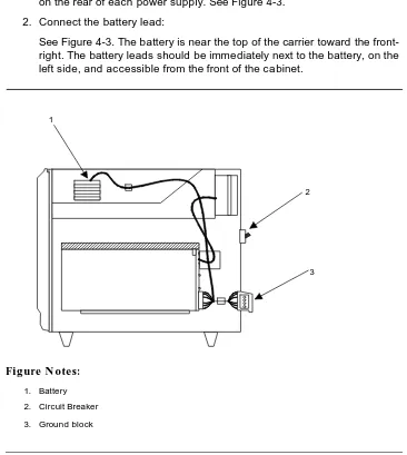
Each cabinet has its own power supply and the circuit breaker is located on the rear of each power supply. See Figure 4-3.
2. Connect the battery lead:
See Figure 4-3. The battery is near the top of the carrier toward the front-right. The battery leads should be immediately next to the battery, on the left side, and accessible from the front of the cabinet.
Figure Notes:
1. Battery
2. Circuit Breaker
3. Ground block
Figure 4-3. Single Carrier Cabinet Control Cabinet Battery Location, Right Side View
1
2
Connect either AC or DC power as described in this section.
Verify the label near the circuit breaker on the power supply toward the rear of each cabinet corresponds to your local voltage type.
!
DANGER:
If the label is different than the voltage type at your site, notify your A T & T representative immediately for a replacement power supply. Do not, under any circumstances, connect to power!
Connect AC Power
Figure 4-2 applies to multiple Processor Port Networks (PPN) and Expansion Port Network (EPN) cabinet arrangements. If multiple Expansion Port Network (EPN) cabinets are required, you must provide the receptacles for the 4-cabinet Processor Port Network (PPN) arrangement in addition to the receptacles for a 2-, 3-, or 4-cabinet Expansion Port Network (EPN) arrangement. Provide one receptacle per single-carrier cabinet.
1. Verify the circuit breakers are OFF .
2. Connect cabinet AC line cords to the AC power receptacles. The AC line cords for the cabinets must first be connected to the cabinets and then to the AC power receptacles.
Connect DC Power
The following procedures apply to both the Processor Port Networks (PPN) and Expansion Port Networks (EPN).
Connect Power
GRD -48V -48V RTN 1
GRD -48V -48V RTN 1
GRD -48V -48V RTN 1
GRD -48V -48V RTN 1
-48V RTN
-48V
GRD 1
1
1
1
1
1
1
1
3
8
13
18 4
9
14 5
5
10
15
15
15
15 1
1
1
6
11
11
16
16
16 2
2
2
2
7
7 7
12
17
(-48V RTN & GRD)
75A -48V
-48V
Figure 4-4. Typical Single-Carrier Cabinet System Direct Current (DC) Power and Grounding Wiring
!
CAUTION:
Grounding of the system shall comply with the general rules for grounding contained in Article 250 of the National Electrical Code (NEC), National Fire Protection Agency (NFPA) 70, or the applicable code in your area. See Appendix G for more information.
Determine the approved ground in the building to be wired. See Ap pendix A. Connect your system to an approved ground as described below.
1. Ground plate (three required)
2. 3 Conductor No.10 line cord (one per cabinet)
3. Plug (male)
4. J58890CG DC Distribution Unit
5. Receptacle (female)
6. Cabinet single-point ground block
7. 6 AWG wire
8. 25 Amp Fuse (4 required)
9. Coupled bonding conductor to terminal bar at cross-connect field
10. Ground discharge bar
11. 1 AWG wire
12. Approved ground
13. To cabinet single-point ground block in next port cabinet
14. To DC distribution unit for next port network
15. 676B DC Power Sup ply
16. Port Cabinet
17. Control Cabinet
Connect Power
Connect Power Plant Ground
To connect the power plant ground, complete the following steps:
1. At the DC power cabinet, connect a 1 AWG ground wire to the GROUND DISCHARGE bar.
2. Route the ground wire out of the cabinet and terminate it on the approved ground (see Figure 4-5). The approved ground must be identified with a grounding tag (AT&T FORM 15657NR, or equivalent).
Figure 4-5. Power Plant Grounding 1
2
3
4
1. 1 AWG wire
2. Approved ground. Must be connected to an approved ground using the correct gauge cable, terminated with a listed clamp, and identified with an AT&T ground tag or equivalent.
3. DC Power Cabinet
Connect the 6 AWG frame ground cable to the cabinet frame by following these steps:
1. Measure and cut a length of 6 AWG cable. Use the provided cable or measure and cut a length of 6 AWG cable long enough to reach between the GROUND CONNECTION terminal in the DC Battery Cabinet and the GROUND DISCHARGE bar in the DC Power Cabinet.
2. Crimp terminal lugs on each end of the wire. Terminal lugs are furnished as part of D-181895, Kit of Parts.
3. At DC power cabinet, connect wire to the GROUND DISCHARGE bar. 4. Route the wire through one of the holes in the side of the cabinet and terminate it on the GROUND CONNECTION terminal in the DC Battery Cabinet (see Figure 4-6).
Figure 4-6. Frame Ground Grounding 1
3 4
5
2
1. 6 AWG wire
2. Ground discharge bar
3. DC battery cabinet
4. Ground connection terminal
Connect Power
Connect DC Power Distribution Box Grounding
Run the 6 AWG ground cable from the DC Power Cabinet to each DC Power Distribution Unit, using the following steps:
1. At the DC Power Cabinet, connect 6 AWG wire to the GROUND DISCHARGE bar. Route the cable to the DC Power Distribution Unit. Connect the cable to the GRD Terminal Block in the DC Power Distribution Unit (see Figure 4-6).
2. Repeat Step 1 for each remaining DC Power Distribution Unit.
Figure 4-7. DC Power Distribution Unit Grounding (J58890CG)
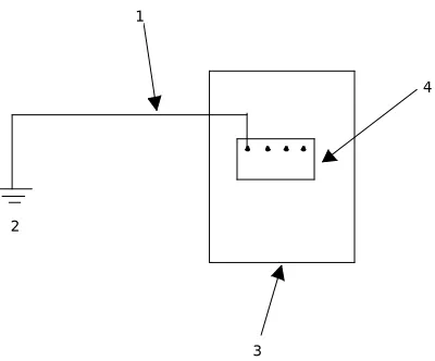
Connect Single-Carrier Network Grounding
Each port cabinet must have a 6 AWG ground cable connected from the ground block of Control Cabinet A to the DC Power Cabinet.
Use the following instructions to connect each network ground: 1
2
3 4
5
6
1. 6 AWG wire
2. To additional J58890CG as provided
3. DC power cabinet
4. Ground discharge bar
5. Power distribution unit
DISCHARGE bar. Route the cable to the port Cabinet Carrier A. Connect the cable to the single-point ground block in the Control Carrier (see Figure 4-7).
2. Repeat Step 1 for each port Cabinet Carrier A in the system.
Figure 4-8. Ground Connection for Single-Carrier Network
Coupled Bonding Conductor (CBC)
The coupled bonding conductor (CBC) connects the cabinet single-point ground block to the approved protective ground located nearest the (telephone company owned) protector block at the building entrance facility. Follow these steps to connect the coupled bonding conductor:
1
2
3 4
5 6
7
8
9
10
1. 6 AWG wire
2. Ground plate
3. Cabinet stack single point ground block
4. To additional Port Cabinet as provided
5. DC Power Cabinet
6. Ground discharge bar
7. Port Cabinet D
8. Port Cabinet C
9. Port Cabinet B
Connect Power
1. Connect a 10 AWG wire to the power cabinet ground discharge bar. See Figure 4-9).
2. Repeat for each port network cabinet.
NOTE:
A Coupled Bonding Conductor (CBC) must be tie-wrapped to all trunk cables and terminated at the coupled bonding conductor terminal bar.
Figure 4-9. Coupled Bonding Conductor
3
3
3
8
13 4
9
14
14
5
10 15 1
6
11
2
7
12 12
1. 25-Pair tip and ring cables to network cabinets.
2. Coupled bonding conductor terminal block
3. Tie wraps
4. Cable shield or six spare pairs
5. Ground on carbon block protector or equivalent
6. To external trunk interface
7. 10 AWG wire
8. Trunk cable
9. To network cabinets
10. Battery plant ground discharge bar for DC or AC system single point ground
11. Cross-connect ground block
12. Cross-connect field
13. To other cross-connect ground blocks
14. Approved Ground
!
CAUTION:
System grounding shall comply with the general rules for grounding contained in Article 250 of the National Electrical Code (NEC), National Fire Protection Agency (NFPA) 70, or your applicable local electrical code. See Appendix A for a description of “approved ground.”
Connect DC Power to Networks
Each port cabinet stack must have a DC Power Distribution Unit associated with it. Each DC Power Distribution Unit furnishes DC power for four single-carrier cabinets. The DC Power Distribution Unit comes equipped with four power cords. Each 10 foot (3 meter) cord is equipped with the appropriate connectors. Perform the following to connect each network to the DC Power Distribution Unit:
1. Connect 1 AWG wire for -48V and -48V return from DC Battery Plant to each DC Power Distribution Unit.
2. At the J58890CG DC Power Distribution Unit, connect the power cable to an available receptacle. Route the cable to the rear of Cabinet A.
Connect the power cord to the DC connector on the rear of Cabinet A. 3. Repeat Step 1 for Cabinets B, C, and D as required.
4. Repeat Steps 1 and 2 for all remaining port cabinets.
Connect AC Power to DC Power Cabinet
Connect the AC power to the DC Power Cabinet by performing the following: 1. Ensure the associated circuit breakers at the AC power panel OFF. 2. Have an electrician connect AC power leads to the rectifiers using the
instructions provided with the rectifiers in the DC Power Cabinet. Each rectifier should have its own branch circuit. Terminate leads on the AC INPUT terminal block of each rectifier.
Test DC Power Plant
To test the DC power plant, refer to the Installation Test Procedure (ITP) in the
LINEAGE 2000 ECS Power System Battery Plant Product Manual, 167-790-020.
Connect Stand-by Power
Locate and Connect Time Division Multiplexing (TDM) Bus
Locate and Connect Time Division
Multiplexing (TDM) Bus
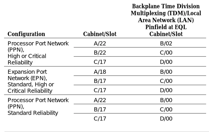
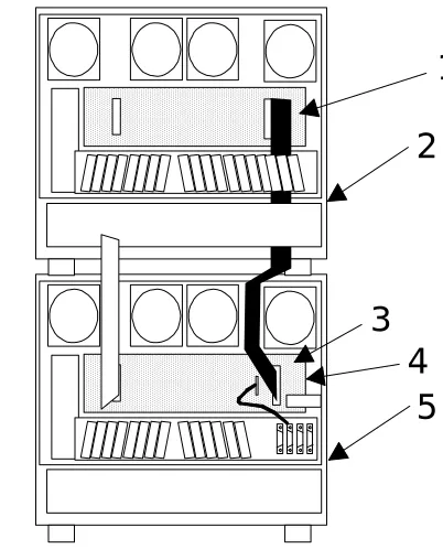
Locate the white fabric-covered Time Division Multiplexing (TDM) bus cable. Refer to Table 4-1 for slot information.
Follow these instructions to connect the bus to the appropriate slots.
1. Remove the Time Division Multiplexing (TDM) bus terminator on Slot 22 of Control Cabinet A and move it to the Time Division Multiplexing
(TDM)/Local Area Network (LAN) pinfield at the equipment location (EQL) on the top port cabinet. See Figure 4-10.
2. Connect the bus cables as shown in Figure 4-10. The cable is located behind the lower panel when the cabinet is shipped.
Table 4-1. Time Division Multiplexing (TDM) Bus Connections
Configuration Cabinet/Slot
Backplane Time Division Multiplexing (TDM)/Local
Area Network (LAN) Pinfield at EQL
Cabinet/Slot
Processor Port Network (PPN),
High or Critical Reliability
A/22 B/02
B/22 C/00
C/17 D/00
Expansion Port Network (EPN), Standard, High or Critical Reliability
A/18 B/00
B/17 C/00
C/17 D/00
Processor Port Network (PPN),
Standard Reliability
A/22 B/00
B/17 C/00
Figure 4-10. Time Division Multiplexing (TDM) Bus Connections for Standard-Reliability Processor Port Network (PPN)
AAAA AAAA AAAA AAAA AAAA AAAA AAAA AAAA AAAA AAAA AAAA AAAA AAAA AAAA AAAA AAAA AAAA AAAA AAAA AAAA AAAA AAAA AAAA AAAA AAAA AAAA AAAA AAAA AAAA AAAA AAAA AAAA AAAA AAAA AAAA AAAA A A A A A A AAAA AAAA AAAA AAAA AAAA AAAA AAAA AAAA AAAA AAAA AAAA AAAA AAAA AAAA AAAA AAAA AAAA AAAA AAAA AAAA AAAA AAAA AAAA AAAA AAAA AAAA AAAA AAAA AAAA AAAA AAAA AAAA AAAA AAAA AAAA AAAA AAAA AAAA AAAA AAAA AAAA AAAA A A A A A A A 3 3 2 4 1 5 AAAA AAAA AAAA AAAA AAAA AAAA AAAA AAAA AAAA AAAA AAAA AAAA AAAA AAAA AAAA AAAA AAAA AAAA AAAA AAAA AAAA AAAA AAAA AAAA AAAA AAAA AAAA AAAA AAAA AAAA AAAA AAAA AAAA AAAA AAAA AAAA A A A A A A AAAA AAAA AAAA AAAA AAAA AAAA AAAA AAAA AAAA AAAA AAAA AAAA AAAA AAAA AAAA AAAA AAAA AAAA AAAA AAAA AAAA AAAA AAAA AAAA AAAA AAAA AAAA AAAA AAAA AAAA AAAA AAAA AAAA AAAA AAAA AAAA A A A A A A 1 3 2 4 2 4
1. Time Division Multiplexing (TDM) bus terminator AHF110 on Time Division Multiplexing)/Local Area Network pinfield (TDM/LAN)
2. Time Division Multiplexing/Local Area Network pinfield (TDM/LAN) at equipment location (EQL) (see Table 4-1 on page 4-15)
3. Time Division Multiplexing (TDM) bus cable WP91716 L3
4. Port cabinet (standard reliability), or duplicate control cabinet (high or critical reliability)
Locate and Connect Inter-Cabinet Cables (ICC)
Locate and Connect Inter-Cabinet
Cables (ICC)
Connect the Inter-Cabinet Cables (ICC) using these steps:
1. Remove the Inter-Cabinet Cable (ICC) from the lower back shelf of the cabinet.
2. Connect the cables as shown in Figure 4-11 and Table 4-2.
Table 4-2. Inter-Cabinet Cable Connections
From Cabinet A To Cabinet B
Cabinet Carrier Connection Carrier Connection
Processor Port Network (PPN)
J58890L (ICC) A J58890M (ICC) A
(ICC) B (ICC) B
(ICC) C (ICC) C
Expansion Port Network (EPN)
J58890N (ICC) A J58890H (ICC) A
Figure 4-11. Inter-Cabinet Cable (ICC) Connections for Standard Reliability Expansion Port Network (EPN) Cabinet Stack
AAAA AAAA AAAA AAAA AAAA AAAA AAAA AAAA AAAA AAAA AAAA AAAA AAAA AAAA AAAA AAAA AAAA AAAA AAAA AAAA AAAA AAAA AAAA AAAA AAAA AAAA AAAA AAAA AAAA AAAA AAAA AAAA AAAA AAAA AAAA AAAA AAAA AAAA AAAA AAAA AAAA AAAA AAAA AAAA AAAA AAAA AAAA AAAA AAA AAA AAA AAA AAA AAA AAA AAA AAAA AAAA AAAA AAAA AAAA AAAA AAAA AAAA AAAA AAAA AAAA AAAA AAAA AAAA AAAA AAAA AAAA AAAA AAAA AAAA AAAA AAAA AAAA AAAA AAAA AAAA AAAA AAAA AAAA AAAA AAAA AAAA AAAA AAAA AAAA AAAA AAAA AAAA AAAA AAAA AAAA AAAA AAAA AAAA AAAA AAAA AAAA AAAA AAA AAA AAA AAA AAA AAA AAA AAA
1
2
3
4
5
1. Pinfield per Table 4-2
2. Cabinet in Position B
3. Inter-Cabinet Cables
4. Backplane
5. Control Cabinet A Position
Install Fibre-Optic Cables
Install Fibre-Optic Cables
This section discusses the hardware and methods required to connect and route fibre-optic cables.
The Expansion Port Network (EPN) cabinet is normally positioned next to the Processor Port Network (PPN) cabinet(s), but may also be installed in a different room or a different building. Fibre-optic cables connect the cabinets together.
Fibre-Optic Cable Operation
Fibre-optic cables carry signals between the cabinets that compose your switch. To do this, the electronic signals at the connectors on the back of a cabinet are converted into optical signals. The optical signals from another cabinet are then converted back into electronic signals. AT&T provides opto-electronic devices, the 9823-type lightwave transceivers, that perform this task. A completed signal from one cabinet goes through a transceiver, a fibre-optic cable, and another transceiver to reach another cabinet. If the two cabinets are close together, the optical signal may go through a single, directly connected fibre-optic cable. If the two cabinets are far apart, it may be convenient to connect the cabinets through the cross-connect field.
Figure 4-13 shows how to connect fibre-optic cables for direct connections. Figure 4-14 shows how to connect fibre-optic cables through a cross-connect field. .
Locate Fibre-Optic Cable Connections
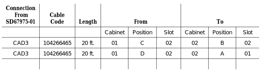
Packed with the system is a Customer Service Document (CSD) that includes an “Inter-Cabinet Cable Running List.” Each row on the list represents a fibre-optic cable connection.
The list includes the AT&T comcode of the cable to be used, its length (in feet) and the addresses of each cable’s source and destination. These addresses include the numbers of the cabinets, carrier positions, and slots to which you are to connect the cables. Use the information from the Running List to determine where to connect each fibre-optic cable.
Figure 4-12. Typical Fibre-Optic Cable Running List
In the example Running List in Figure 4-12, connect a cable labeled 104266465 (20 feet long) from Cabinet 1, Carrier C, Slot 2, to Cabinet 2, Carrier B, Slot 2.
NOTE:
The following tasks refer to the Running List and offer typical installation instructions. If any conflict between specific details in the Running List and the instructions given in the following procedures arise, cable your system according to the Running List provided with your system.
General Rules and Recommendations for
Connecting Fibre-Optic Cables
Although fibre-optic cables withstand some misuse, it does require careful handling and routing.
Follow these rules and recommendations when installing fibre-optic cables:
Rule 1
Cross-connect the fibre-optic cable between two 9823-type lightwave transceivers. That is, run the cable from the connector marked TX on one transceiver to the connector marked RX on the other transceiver, and in reverse for the other cable.
Do this for each connection (row) on the Running List contained in the Customer Service Document (CSD) shipped with your system. See Figure 4-12 for a sample Running List.
Rule 2
Use the 9823A (shortwave) transceiver for distances of up to 4900 feet. Use the 9823B (longwave) transceiver for distances of up to 25,000 feet. Ensure all 9823As are connected to 9823As and all 9823Bs are connected to the corresponding 9823Bs.
Connection From SD67975-01
Cable
Code Length From To
Cabinet Position Slot Cabinet Position Slot
CAD3 104266465 20 ft. 01 C 02 02 B 02
Install Fibre-Optic Cables
Rule 3
Route fibre-optic cables away from groups of other cables where they may be stretched by the weight of metal cable bundles, as fibre-optic cables are quite flexible.
Rule 4
Avoid bending fibre-optic cables to a radius smaller than 1-1/2 inches (4 cm), to prevent mechanical stress on the cables, as they are rather delicate. Plan your use of cable ties to avoid crimping the cable or creating a fixed stress point where, at a later time, movement of the cable causes it to exceed the minimum bend radius.
Rule 5
Ensure fibre-optic cables are not pressed against any sheet metal edges by subsequently installed cables.
Recommendation
In some such systems it may be required to run fibre-optic cables with the input/output cables, such as in the cable slack manager or under a raised floor. In these situations, protect the cable by running it in a dedicated area if
possible. When you must run the cable with other cabling, protect it by running it through flexible conduit.
Figure 4-13. Fibre-Optic Cable Installation Between Shortwave Transceivers, Direct Connection
TX
RX
1
2
2
1
TX
RX 1
2
3
4
1. Processor Port Network (PPN) Cabinet A Slot 2A01 / 9823-Type lightwave transceiver
2. FL2P-P-20 Fiber optic cable
3. Expansion Port Network(EPN) Cabinet A Slot 1A01 / 9823-Type lightwave transceiver
4. Fiber optic cable sheath, containing two fibers, each labeled 1 and 2,
Install Fibre-Optic Cables
Figure 4-14. Fibre-Optic Cable Installation Between Longwave Transceivers Through Fibre-Optic Cross-Connect Field
Raised Floor or Cable Slack Managers
Figure 4-15 shows the recommended fibre-optic cable routing for a single-carrier cabinet system with a cable slack manager or on a raised floor. In these situations, use the following steps to route the cable:
1. Route the fibre-optic cable up toward the top of the cabinet. The excess cable should be looped and draped from the B25A cable clamp on the top ground plate in the stack.
2. Dress the cable running up the back of the cabinets by tie wrapping the cable to the outside of the B25A cable clamp (do not put the cable inside the clamp holding the B25A cables).
TX
RX
1
2
2
1
TX
RX 1
2
3
4 5
6
1. Processor Port Network (PPN) Cabinet A Slot 2A01 / 9823-Type lightwave transceiver
2. FL2P-P-20 Fiber optic cable
3. Expansion Port Network (EPN) Cabinet A Slot 1A01 / 9823-Type lightwave transceiver
4. Fiber optic cable sheath, containing two fibers, each labeled 1 and 2,
respectively
5. 100A LIU
Do not route fibre-optic cables and the B25A cables together.
Figure Notes:
Figure 4-15. Single-Carrier Cabinet Fibre Routing
Cable Connections
When routing fibre-optic cables, connect the cables (according to the Running List provided in the Customer Service Document (CSD)) to the
transceiver, and plug the transceiver into the appropriate slot on the back of the cabinet, as illustrated in Figure 4-16 through Figure 4-18.
3 4
4
4
4
4
4
5 5
1
2
1. B25A Cables
2. Loop and Drape Excess Fiber Optic Cable. Do Not Route Fiber Optic Cable and B25A Cables Together.
3. Fiber Optic Cable Sheath
4. Port Cabinet
Install Fibre-Optic Cables
Standard Reliability Fibre-Optic Cable
Connections
For Standard Reliability system configuration, route the fibre-optic cable as illustrated below.
Figure 4-16. Fibre-Optic Cable Connections for Standard Reliability Single-Carrier Cabinet System
1 2 3 4 5 6 7 8 9 10 11 12 13 14 15 16 17 18 1 2 3 4 5 6 7 8 9 10 11 12 13 14 15 16 17 18 1 2 3 4 5 6 7 8 9 10 11 12 13 14 15 16 17 18 1 2 3 4 5 6 7 8 9 10 11 12 13 14 15 16 Terminal AUX A B C D
Port Cabinet Port Cabinet Port Cabinet Control Cabinet
1 2 3 4 5 6 7 8 9 10 11 12 13 14 15 16 17 18 1 2 3 4 5 6 7 8 9 10 11 12 13 14 15 16 17 18 1 2 3 4 5 6 7 8 9 10 11 12 13 14 15 16 17 18 B C D
Port Cabinet Port Cabinet
Port Cabinet 1 2 3 4 5 6 7 8 9 10 11 12 13 14 15 16 17 18 1 2 3 4 5 6 7 8 9 10 11 12 13 14 15 16 17 18 1 2 3 4 5 6 7 8 9 10 11 12 13 14 15 16 17 18 B C D
Port Cabinet Port Cabinet
Port Cabinet 1 2 3 4 5 6 7 8 9 10 11 12 13 14 15 16 17 18 A
Expansion Control Cabinet
1 2 3 4 5 6 7 8 9 10 11 12 13 14 15 16 17 18 A
Expansion Control Cabinet
Terminal Terminal AUX AUX AAAA AAAA AAAA AAAA AAAA AAAA AAAA AAAA AAAA AAAA AAAA AAAA AAAA AAAA AAAA AAAA AAAA AAAA AAAA AAAA AAAA AAAA AAAA AAAA AAAA AAAA AAAA AAAA AAAA AAAA AAAA AAAA AAAA AAAA AAAA AAAA AAAA AAAA AAAA AAAA AAAA AAAA AAAA AAAA AAAA AAAA AAAA AAAA AAAA AAAA AAAA AAAA AAAA AAAA AAAA AAAA AAAA AAAA AAAA AAAA AAAA AAAA AAAA AAAA AAAA AAAA AAAA