AT&T SYSTEM 25
R2V1
Contact: Your AT&T sales representative, or
Call: 800-432-6600, Monday through Friday between 7:30 am and 6:00 pm EST, or
In Canada call: 800-255-1242
Write: AT&T Customer Information Center 2855 North Franklin Road P.O. Box 19901
Indianapolis, Indiana 42619
Every effort was made to ensure that the information in this document was complete and accurate at the time of printing. However, this information is subject to change. This document will be reissued periodically to incorporate changes.
R2V1 Reference Manual Prepared by System 25
Document Development Group and the AT&T Documentation
following:
MEANS OF CONNECTION
Connection of this telephone equipment to the nationwide telecommunications network shall be through a standard network interface USOC RJ21X jack. Connection to private line network channels requires USOC RJ2GX jack for tie lines or USOC RJ21X jack for off-premises station lines. These can be ordered from your telephone company.
NOTIFICATION TO THE TELEPHONE COMPANY
If the system is to be connected to off-premises stations (OPSs), you must notify the telephone company of the OPS class of service, OL13C, and the service order code, 9.0F.
Upon the request of the telephone company, inform them of the following:
—
—
—
—
—
The Public Switched Network “lines” and the Private “lines” to which you will connect the telephone equipment.
The telephone equipment’s “registration number” and “ringer equivalence number” (REN) from the label on the equipment.
For private line connections, provide the facility interface code, TL31M for tie lines. You must also specify the service order code, 9.0F.
The quantities and USOC numbers of the jacks required.
For each jack, provide the sequence in which lines are to be connected; the type lines and the facility interface code and the ringer equivalence number by position, when applicable.
This telephone equipment should not be used on coin telephone lines. Connection to party line service is subject to state tariffs.
REPAIR INSTRUCTIONS
Your telephone company may make changes in its facilities, equipment, operations, or procedures that could affect the proper functioning of your equipment. If they do, you will be notified in advance to give you an opportunity to maintain uninterrupted telephone service.
HEARING AID COMPATIBILITY
The voice terminals described in this manual are compatible with inductively coupled hearing aids as prescribed by the FCC.
FCC REGISTRATION INFORMATION
Registration Number AS593M-71565-MF-E
Ringer Equivalence 0.5A
Network Interface RJ21X or RJ2GX
PRIVATE LINE SERVICE
Service Order Code 9.0F
Facility Interface Code
● This equipment generates, uses, and can radiate radio frequency energy and, if not installed and used in accordance with the instruction manual, may cause interference to radio communications.
● It has been tested and found to comply with the limits for a Class A computing device pursuant to Subpart J of Part 15 of FCC Rules, which are designed to provide reasonable protection against such interference when operated in a commercial environment.
● Operation of this equipment in a residential area is likely to cause interference in which case the user at his or her own expense will be required to take whatever measures may be required to correct the interference.
DANGER
C O N T E N T S
Section 1—Overview
Section 2—Features and Services
Section 3—Functional Description
Section 4—Hardware Description
Section 5—Technical Specifications
Section 6—Environmental Requirements
Section 7—Parts Information
Section 8—Reference Documentation
Section 9—Glossary
System 25 Description
Call Handling Capabilities
Safety
Business Communications Needs
Incoming Business Communications
Outgoing Business Communications
Internal Call Movement
Data Communications
Growth & Rearrangement
Conclusions
1-1
1-4
1-4
1-5
1-5
1-7
1-9
1-10
1-13
OVERVIEW
Introduction
This reference manual provides general technical information on AT&T System 25 (System 25). It includes a description of the system, its hardware and software, features and services, environmental requirements, and technical specifications. This manual is intended to serve as an overall technical reference for System 25.
This manual is released specifically to cover Release 2 Version 1 (R2V1) of System 25. It does not contain information that applies only to the earlier releases of System 25.
Organization
This manual is divided into 10 sections. The remaining sections are as follows:
● SECTION 2—FEATURES AND SERVICES
● SECTION 3—FUNCTIONAL DESCRIPTION
● SECTION 4—HARDWARE DESCRIPTION
● SECTION 5—TECHNICAL SPECIFICATIONS
● SECTION 6—ENVIRONMENTAL REQUIREMENTS
● SECTION 7—PARTS INFORMATION
● SECTION 8—REFERENCE DOCUMENTATION
● SECTION 9—GLOSSARY
● SECTION 10—INDEX.
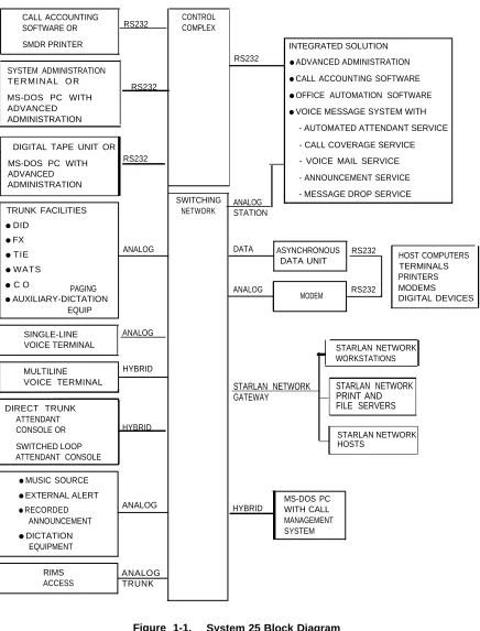
System 25 Description
CONTROL COMPLEX CALL ACCOUNTING
SOFTWARE OR RS232
SMDR PRINTER INTEGRATED SOLUTION
● ADVANCED ADMINISTRATION
● CALL ACCOUNTING SOFTWARE
● OFFICE AUTOMATION SOFTWARE
● VOICE MESSAGE SYSTEM WITH - AUTOMATED ATTENDANT SERVICE - CALL COVERAGE SERVICE - VOICE MAIL SERVICE - ANNOUNCEMENT SERVICE - MESSAGE DROP SERVICE RS232
SYSTEM ADMINISTRATION T E R M I N A L O R
RS232 MS-DOS PC WITH
ADVANCED ADMINISTRATION
DIGITAL TAPE UNIT OR
MS-DOS PC WITH RS232
ADVANCED ADMINISTRATION ANALOG STATION SWITCHING NETWORK TRUNK FACILITIES
● DID
● FX
● TIE
● WATS
● C O PAGING
● AUXILIARY-DICTATION EQUIP
DATA ASYNCHRONOUS RS232
DATA UNIT HOST COMPUTERS
TERMINALS PRINTERS
ANALOG RS232 MODEMS
MODEM DIGITAL DEVICES
ANALOG
SINGLE-LINE ANALOG
VOICE TERMINAL STARLAN NETWORK
WORKSTATIONS
MULTILINE HYBRID
VOICE TERMINAL STARLAN NETWORK
GATEWAY STARLAN NETWORK PRINT AND FILE SERVERS DIRECT TRUNK ATTENDANT
CONSOLE OR HYBRID
SWITCHED LOOP ATTENDANT CONSOLE
STARLAN NETWORK HOSTS
● MUSIC SOURCE
● EXTERNAL ALERT
● RECORDED ANNOUNCEMENT
● DICTATION EQUIPMENT
MS-DOS PC HYBRID WITH CALL MANAGEMENT SYSTEM ANALOG
RIMS ANALOG
ACCESS TRUNK
Voice communications features combine traditional telephone features, such as Transfer and Hold, with advanced features, such as Individual and Group Coverage, Hands-Free Answer On Intercom, and Speed Dialing (see Section 2, “Features and Services”).
Data communications features provide switched data connections supporting transmission of voice and data over Premises Distribution System wiring. Data connections can be made between two digital data modules (asynchronous data units), between two analog modems, or between an analog modem and a digital data module. System 25 also provides access to STARLAN NETWORKs (Release 2 of STARLAN only). The system has data modules that provide an RS-232 interface for full duplex, asynchronous, transmission of data up to 19,200 bps, and an integrated 212A-compatible modem pool resource.
System 25’s Integrated Solution offers customers a unique package of integrated call management, switch management, and office automation applications. The Integrated Solution is a set of application programs that run on a Master Controller (UNIX® PC). The applications include Advanced Administration Software (AAS), which permits customers to administer System 25’s features themselves; Call Accounting System (CAS); and an integrated Voice Message System (VMS) that provides call coverage, leave word calling, automated attendant, and voice mail services. In addition, a number of generic office automation applications (word processing, data base management, and spreadsheet) are also available for the Integrated Solution; these applications may be run simultaneously with the VMS and CAS applications.
System 25 supports the following:
● Trunk and Network Facilities— Dual Tone Multifrequency (DTMF) and Dial Pulse
Signaling on incoming and outgoing trunks (dial pulse only on DID trunks).
— Loop Start (LS)
— Ground Start (GS) (Strongly Preferred over Loop Start in most installations)
— Tie Trunks (Type I and Type I Compatible E&M, Type V Simplex)
— Direct Inward Dialing (DID)
● Voice Terminals — Single-Line Touch-Tone, Single-Line Rotary, MET, and 7300H
Series Multiline Sets from the MERLIN® Communications System.
● Data Facilities
— Digital Data End Points — RS-232 Interfaces via Asynchronous Data Units
— Analog Data End Points — Tip/Ring-Type Modem Interfaces
● Networking Capability
— Remote Access
— Tie Trunks
— Tandem Trunking
— Endpoint in Electronic Tandem Network (Tributary only, not Satellite)
— Endpoint of Enhanced Private Switched Communications Services (EPSCS)
— Endpoint of Tandem Tie Trunk Network (TTTN)
— Endpoint of Common Control Switching Arrangement (CCSA).
Call Handling Capabilities
System 25 can be arranged as a stand-alone system or can be part of a private network. The system provides 256 ports to support the following:
● 115 simultaneous two-party conversations
● Traffic Handling Capacity of 4140 CCS (Trunking Limited)
● Busy Hour Call Capacity of 2500 calls (DTMF Register Limited)
● Up to 104 trunk ports including Central Office (CO), DID, Tie, Foreign Exchange (FX),
Wide Area Telecommunications Service (WATS), and 800 Service
● An Auxiliary Trunk interface for paging and dictation systems
● Up to 240 ports that support a combination of the following:
— Up to 200 ports for voice terminals and auxiliary feature port equipment.
— Up to 104 data ports providing RS-232 connections to data terminals, personal or multiport computers.
Refer to Hardware and Software Parameters as provided in ''Technical Specifications” (Section 5) for detailed specifications.
Safety
Business Communications Needs
The remainder of this section describes how System 25’s features may be used to satisfy a customer’s communications needs. This material may be thought of as the reverse of the “Features and Services” in Section 2.
The business communications capabilities of the majority of small businesses with more than 30 phones are provided by a PBX. System 25 is a PBX designed to meet the business communications needs of customers in the 30 to 150 station range.
The communications needs of most business customers may be broken down into five basic categories. Customer experience has shown that a PBX needs to provide—
● Prompt handling of incoming calls to maximize revenue opportunities and client
satisfaction,
● Ease of access to and cost control of outgoing calls over public network and private
facilities,
● Easy movement of calls between on-premises phones and between on-premises and
off-premises phones,
● Sharing of data between PCs and/or host computers and data terminals, and
● Growth and rearrangement of facilities.
The following pages outline System 25’s outstanding ability to provide these services.
Incoming Business Communications
Successful call termination is the key to capturing all incoming communications associated with revenue issues, client inquiries, decision data, etc. Call termination involves identifying the called party and routing the call to a primary or secondary answering position. System 25 provides powerful tools for both call screening and call termination.
● Attendant Consoles allow one or two attendants to answer, screen, and steer
incoming calls using either Direct Trunk or Switched Loop operation. With attendant operation, incoming calls can be screened and extended to the appropriate party for resolution or forwarded to alternate locations, and messages can be taken for absent clients. Calls may arrive over any of the network facilities described in later sections of these notes.
● System 25’s Integrated Solution can provide Automated Attendant service, either
● Direct Inward Dialing allows incoming callers to reach specific individuals or facilities
without attendant assistance. This allows specific numbers to be advertised for direct customer access to brokers, emergency services, etc., over a shared pool of DID trunks.
● The Call Management System provides Automatic Call Distribution (ACD) service and
associated call traffic and agent performance reports.
● Direct Group Calling (DGC) allows incoming calls to be directed to a specific group of
stations. Calls to a DGC group hunt for an idle station in a circular manner, starting at the station following the last one called. If all group members are busy, calls are queued and can be sent to a delay announcement. A DGC group can terminate calls to sales, services, computer, announcement, etc., over either ordinary CO trunks or DID trunks.
● Personal Lines provide dedicated outside lines for multiline voice terminal users and
are accessed via a dedicated button for both incoming and outgoing service. Up to 16 terminals may share a Personal Line with up to 4 parties simultaneously off-hook. A personal line provides direct access to brokers, emergency service, etc., over a dedicated loop start or ground start trunk.
● Call Waiting lets users know that they have another incoming call and helps avoid
missing important calls.
● Remote Access allows employees to use the services and facilities of System 25
from home or when they are on the road. Barrier codes prevent unauthorized access.
Frequently, the called party is not available to handle an incoming call. System 25 provides a number of methods for redirecting incoming calls to alternate resources.
● Coverage allows calls that are not answered within a specified number of rings to be
redirected to an individual covering station and/or a group of covering stations. This is especially useful for Boss-Secretary arrangements, staff backup, and message service. This feature is versatile enough to permit suitable alternate answering arrangements for virtually every level of employee. Special features, such as the Send All Calls feature which routes a user’s calls directly to covering station(s), accommodate the day-to-day variations that occur in an employee’s work schedule.
● Following and Forwarding allow users who are away from their normal locations to
receive their calls at other phones inside the system or (Forwarding only) outside the system. This feature supports roving personnel and shared office space for company staff.
● The Integrated Solution can provide call coverage service, along with integrated voice
mail and Leave Word Calling.
● The Bridging feature permits calls on a user’s System Access buttons to be
● Station Hunting provides automatic redirection of incoming calls to an idle member of
a hunt group when the called party is busy.
● Pickup allows a user to answer a call ringing at another terminal. Directed Pickup
allows a user to answer a call ringing at any terminal by dialing the pickup code and the Personal Dial Code (PDC) of the ringing station. Group Pickup permits calls to any other terminal in the pickup group to be answered by dialing the group call pickup code. With Pickup, users do not have to leave their phone to answer other’s calls. This feature is especially useful for local coverage in group offices not supported by secretarial service and equipped with economical single-line phones.
When alternate resources are not available to handle an incoming call, System 25 provides for attendant handling of the call utilizing camp-on, redirection, and/or message service.
● Camp-On allows the attendant to extend an outside call to a busy station. A burst of
tone is heard at the called station to notify the user of the camped-on call. The caller is placed on hold and hears music-on-hold, if available. When the user hangs up, the camped-on call begins ringing immediately. The Return Coverage on Busy feature returns unanswered camped-on calls to the attendant for service after a specified interval.
● Return Coverage on Don’t Answer returns unanswered attendant-extended calls for
additional service (redirection/messaging).
● Messaging Service supports activation of a light-emitting diode (LED) at the called
station to indicate that the attendant, message desk, or another station has a message for the user.
Special arrangements are needed to handle incoming calls during periods when the normal staff is not available, for example, at night and on weekends. System 25’s Night Service feature allows on-duty personnel to answer incoming attendant-seeking calls when the attendant is not on duty. Directed Night Service redirects incoming attendant-seeking calls to designated voice terminals, such as a guard desk or coverage position. Trunk-Answer-From-Any-Station (TAAS) Night Service allows users to answer incoming calls from any station by dialing the Night Service access code. Night personnel can be alerted by a night bell.
Outgoing Business Communications
One of the key functions of a customer premises communications system is to provide easy access to the most cost effective network facilities for outgoing calls. The system needs to be capable of steering calls based on cost, and must also keep records of incoming and outgoing calls and associated costs. Building on its ground start trunk capability, System 25 features control costs and record usage as follows.
● Call Restrictions allow the manager to restrict users from making certain types of
● Automatic Route Selection provides manager defined routing of calls over the telecommunications network based on preferred routes (normally the least expensive route available at the time the call is placed) with capacity for multiple common carriers and routing through tandem switch points. The user dials a standard Direct Distance Dialing (DDD) number and the system selects the call route.
● Station Message Detail Recording (SMDR) generates detailed call information on all incoming and outgoing calls and sends this information to an output device (PC or printer).
● C a l l A c c o u n t i n g S y s t e m s p r o v i d e m u l t i p l e t y p e s o f c u s t o m e r r e p o r t s o n communication costs and usage.
● Account Code Entry allows a user to associate calls with an account code for charge-back purposes. This feature can be administrated (on a per-station basis) to force the entry of the required codes before outgoing calls can be made.
Ease of access to multiple types of network facilities (provided for minimum cost) is managed by the following features.
● Automatic Route Selection (ARS) allows the customer to dial a standard DDD number. ARS selects the preferred route and does any number conversions required for the facilities selected.
● System 25’s Virtual Facility feature provides convenient and inexpensive access to Other Common Carriers (OCCs). This feature provides access to OCC facilities over a user specified physical facility; dedicated OCC trunks are not needed. Local OCC access numbers and account codes are automatically added by System 25. System 25’s Virtual Facility feature is fully integrated with its ARS, Toll Restriction, and SMDR/CAS features.
● Callback Queuing provides a simple way to complete calls to busy trunk pools without having to manually repeat the calling procedures. Such calls are put into a queue; when the busy facility is available, the originator is alerted and the call is completed.
● Last Number Dialed automatically saves the last number dialed and allows the user to retry the number without redialing (multiline voice terminals only).
● Callback Queuing puts a call made to a busy facility into a queue, notifies the calling user when the facility becomes available to receive the call, and completes the call.
● Repertory Dialing allows multiline voice terminal users to store a telephone number or account and associate that number with a button on their voice terminal. Pressing a Repertory Dialing button is equivalent to dialing the stored number (one-touch dialing).
● Pooled Facility-Dial/Direct Access allows both multiline and single-line voice terminal users to access a common pool of trunks for outgoing calls by dialing a facility access code, or, on multiline voice terminals, by pressing a button. This grouping provides resource pooling, which results in better service with a given number of trunks.
● Personal Lines provide dedicated outside lines for multiline voice terminal users. Personal lines are accessed via a dedicated feature button. Up to 16 terminals may share a personal line.
● Third-Party Call Setup allows PCs to set up calls between a System 25 voice/data terminal and any other facility. A PC application program could use this capability to retrieve information from a data base.
Last Number Dialed, Repertory Dialing, and Speed Dialing are also applicable to dialing and managing internal calls. Personal lines provide both incoming and outgoing service.
Internal Call Movement
Typically, about 40 percent of PBX calls are internal calls, call transfers to another location, conference of multiple locations, temporarily suspended calls, page to locate the called party, etc. Rapid placement of internal calls and easy call movement from the answering station to a new station are supported with numerous features in System 25.
To provide easy internal call setup, System 25 provides the following
● Direct Station Selection (DSS) allows one-button access
features.
from a multiline voice terminal to another voice terminal, a pooled facility, paging zone, or DGC group. The DSS status LED reflects the idle/busy status of the associated termination point. This feature is used to track and contact frequently called associates.
● Automatic Intercom allows multiline voice terminal users to call each other by use of a dedicated line appearance. A private dedicated path ensures that a path is always available. This feature is frequently used in Boss/Secretary arrangements.
Efficient internal call termination is supported with the following features.
● Distinctive Ringing provides various patterns of ringing to allow users to distinguish outside calls, inside calls, callbacks on queued calls, and calls set up at an associated data terminal.
● Hands-Free Answer on Intercom (HFAI) allows Speakerphone and HFAI terminals to auto-answer inside or attendant extended calls. With HFAI active, the set generates a tone burst over its speaker to alert the calling and called party of the call completion. Both parties may then converse; no action by the called party is required.
Frequently, the first termination point for a call is not its final destination. To support internal call movement, System 25 provides the following features.
● Bridging of System Access and Personal Lines allows calls to be passed in a manner that key system users are familiar with.
● Transfer allows a user to transfer any call to another voice terminal. This feature supports transfer of calls from the answering position to another location for completion of a transaction. Examples are secretary to boss, office to lab, broker to specialist, etc.
● Conference allows up to five parties (maximum two outside), including the originator, to participate in a call. This feature supports add-on of additional parties to a call for joint consultation, crisis management, schedule coordination, etc.
● Hold allows a user to suspend a call. The Hold feature allows users to temporarily disconnect from one conversation and either place or answer another call. Music or information bulletins may be provided to the held party. Called parties frequently use the hold period to access computer data bases, search categories, and/or consult with others via a second phone call.
● Following and Forwarding provide users with ways to answer their incoming calls while temporarily away from their home terminals.
● Park allows a user to place a call or conference on hold and then pick up the call from any voice terminal. The user can page another party to pick up the parked call or may move to another location and then re-access the call.
Data Communications
following features.
● Circuit switched data communications up to 19,200 bps (RS-232 interface) provide circuit switched connections from asynchronous data terminals, PCs, or host computers to host computers or network facilities. Users can be located and/or moved to any on-premises office equipped with the standard AT&T 4-pair wiring plan. Thus an asynchronous terminal or PC can have access to multiple host computers, remote data bases via a modem pool, and a local area network (STARLAN) via System 25’s STARLAN NETWORK gateway.
● Packet switched data connections at 1 million bps over AT&T’s STARLAN NETWORK local area network provide data transfer between client PCs and servers (PCs/host computers/printers, etc.) on the local area network (LAN). LAN users can be located and/or moved to any on-premises office equipped with standard AT&T 4-pair wiring. The LAN allows PCs to share facilities (printers, disk systems, modem pools, etc.).
● System 25’s STARLAN NETWORK ACCESS software and STARLAN NETWORK gateway provide access to the STARLAN NETWORK for off-premises and occasional on-premises users. These users do not need to install a Network Access Unit (NAU) in their PCs to use the STARLAN NETWORK ACCESS software. The data transfer rate is limited to 9600 bps or, for off-premises users, by the modem.
Note: System 25 is compatible only with Release 2 of the STARLAN NETWORK.
LAN users can access hosts connected to System 25, or, if their System 25 is equipped with a modem pool, remote hosts. Finally, terminals and PCs connected to System 25 data ports can access host computers on the LAN.
Frequently a user needs to access a LAN data base at or from a remote location (home, motel, client office, branch, etc.). To support out-of-building access to computer data over network facilities or Off-Premise Station (OPS) lines, System 25 provides the following features.
● Modem pooling allows data terminals to communicate over analog facilities utilizing the standard dialing plan and provides full access to all network facilities, cost control mechanisms, ARS, and incoming call management tools (DID/attendant/DGC, etc.).
● Transfer to data allows a data call to be set up on a voice terminal and then to be transferred to a data terminal or computer, This feature can also be used to enter an account code for the data call.
● The System 25 STARLAN NETWORK gateway allows the LAN environment to be extended to occasional users or remote locations. Off-premises users can access the LAN utilizing all the network features, cost control mechanisms, and incoming call management facilities of System 25. The data transfer rate is governed by the modem.
● The integrated voice-data dialing plan recognizes the different types of data endpoints (digital/ analog and remote/Iocal) in a connection and automatically inserts the required data communication equipment. In addition, autobauding supports the alignment of equipment with the capacity to transmit at different data rates.
● Station Hunting supports the use of a single dial code to access a group of host computer ports.
● Terminal Dialing provides the user with fast access to data communications via keyboard dialing at a terminal or PC.
● Command Mode provides a menu of data services supporting terminal dialing and display and control of user data port options. A user friendly Change Options menu is provided for user administration of data options.
● Expert Mode is an enhancement that provides an alternative method of accessing Command Mode functions. It eliminates the display of menus and allows multiple commands to be entered on a single line. Expert mode is suitable for use with computer-driven scripts for call setup.
● Communication Access Manager (CAM) is an MS-DOS* software application that provides a phone manager for placing voice and data calls for the user and VT100† terminal emulation. CAM may be used on either STARLAN NETWORK client workstations or on PCs connected to System 25. CAM has a 200-entry directory with one-touch dialing for both voice and data calls and auto-login capability for data calls to host computers. CAM’s Remote Access feature provides password protected unattended access to PC files and electronic mail. File transfer is supported with the popular XMODEM protocol.
● STARLAN NETWORK ACCESS is an MS-DOS software application that allows PCs not connected to the STARLAN NETWORK to call through the System 25 STARLAN NETWORK Interface and run STARLAN NETWORK client software to access file and printer servers on the STARLAN NETWORK. ACCESS uses a PC’s serial communications port to communicate with the STAR LAN NETWORK Interface. ACCESS is compatible with NETBIOS, permitting execution of most applications written for the IBM‡ PC Network and IBM Token Ring Network.
* Registered trademark of Microsoft Corp. † Trademark of Digital Equipment Corp.
Growth & Rearrangement
Historical data indicates that clients in the System 25 station range have a need for communications systems capable of significant growth and rearrangement. Clients need flexibility over the life of the system to easily add capacity, move stations, modify cost control options, etc. The architecture of System 25 was implemented with the objective to meet this need.
● Advanced Administration (optional) is an easy-to-use, menu driven personal computer software package for configuring the rich set of system options. Versions of this software are available for both MS-DOS and UNIX personal computers.
● Uniform Wiring Plan (four-pair) allows a building to be prewired for the rich set of AT&T Small Business PBX service offerings. This modular wiring plan supports client reconfiguration of an office with variations in station type (Analog, MET, MERLIN Communications System, futures) and data configurations (LAN, asynchronous, synchronous). It supports simultaneous voice and data from standard 4-pair modular jacks.
● System 25/75/85 Standard Architecture supports efficient growth with modular cabinets, universal carrier slots, nonblocking network, and uniform wiring plan. Every circuit slot in the system can be used for trunk cards or voice/data station cards. All these attributes allow the client to add future capability without breakage and re-engineering of existing equipment. Thus, the client is able to minimize initial investment while not restricting future growth.
Over time, the type of tools and facilities that a business utilizes changes. It is important that a PBX provide support for the full set of telephone company network options over its installed life, even when only a subset is initially used. Trunks link two switching systems, such as System 25 and the local Central Office or System 25 and another PBX. System 25 supports five different telephone company trunk interfaces to provide desired connectivity at minimum expense. Thus the opportunity exists to select the best trunk types, depending on tariffs and customer needs. For example:
● Loop Start (LS) trunks for public network access at minimum tariff. These trunks handle outgoing and incoming attendant calls, incoming DGC calls, outgoing pooled facility calls, and personal line calls.
● Ground Start (GS) trunks for public network access. These trunks handle the same type of calls as LS trunks. They provide protection against call reorigination without toll restriction, more reliable automatic route selection, virtual facilities, SMDR, and CAS. Simultaneous incoming and outgoing call seizure of the same trunk under heavy traffic conditions is essentially eliminated with ground start trunks. GS trunks should usually be selected in preference to LS trunks unless tariff considerations are overriding. Note, however, that Centrex Service requires LS trunks.
● Tie Trunks for linking PBXs with dedicated private circuits for high volume calling. Dial access to stations, other trunks, answering groups (Direct Group Calling), and an Electronic Tandem Network endpoint capability are provided.
● Off-Premises Stations (OPS) allow a single-line voice terminal to be located remotely and connected to System 25 via arrangements with the local telephone company. This service is used to provide users at secondary sites (or their residences) many of the same features as an on-premises single-line station.
To enhance the usage and control of the above set of network facilities, System 25 provides the rich set of access features outlined in the Outgoing Business Communications section. In addition, System 25 can support networking between systems by:
● Serving as an endpoint on an electronic tandem network (ETN) using its tie trunks and flexible dialing plan.
● Serving as an off-network or on-network access point with its dial access/transfer between tie trunks and telephone company trunks (LS/GS/DID). This allows usage of tie trunks to reach a distant System 25 and then connect through that System 25 to local telephone company facilities to complete the call.
To support efficient utilization of trunks, they can be grouped together (up to 16 groups) if all trunks in the group perform
the same
function. This resource pooling provides better service with a given number of trunks, and simplifies administration and calling.Types of trunks that can be assigned in System 25 are as follows.
Central Office, which provide a link with the local telephone company for incoming and outgoing calls (LS/GS)
Foreign Exchange (FX), which connect to a CO other than the local CO for high volume calling to/from a distant location
Wide-Area Telecommunications Service (WATS), which connect to an Outward WATS office or a dial “800” Service Office
Direct Inward Dialing (DID), which provide incoming service from a CO to directly access a station or facility (STARLAN NETWORK interface, trunk group)
Tie, which provide a link with another private switching system.
Conclusions
Account Code Entry, Optional
2-11Attendant Call Extending
Attendant Camp-On
Attendant Cancel
Attendant Console, Direct Trunk
Attendant Console, Switched Loop
Attendant Direct Extension Selection
Attendant Forced Release (SLAC Only)
Attendant Join (SLAC Only)
Attendant Message Waiting
Attendant Position Busy
Attendant Release
Attendant Return Coverage On Busy
Attendant Return Coverage On Don't Answer
Attendant Source and Destination (SLAC Only)
Attendant Splitting One-Way Automatic
Attendant System Alarm Indication
Automatic Intercom
Automatic Route Selection (ARS)
2-14
2-16
2-18
2-19
2-24
2-34
2-39
2-40
2-41
2-43
2-46
2-48
2-50
2-52
2-53
2-54
2-55
2-57
Bridging of System Access Buttons
Busy-To-Idle Reminder
2-67
Calling Restrictions
Call Management System (CMS)
Call Progress Tones
Call Waiting
Command Mode
Communications Access Manager (CAM)
Conference
Conference Drop
Coverage, Group
Coverage, Individual
Data Call Setup
Data Services Overview
Data Terminal Dialing
Dial Access to Message Waiting Indicators
Dial Plan
Dictation System Access
Digital Tape Unit (DTU)
Direct Group Calling (DGC)
Direct Group Calling Delay Announcement
Direct Inward Dialing (DID)
Directory
2-88
2-91
2-94
2-95
2-97
2-101
2-103
2-106
2-108
2-114
2-117
2-118
2-124
2-128
2-129
2-132
2-134
2-136
2-139
2-141
End-To-End Signaling
Exclusion
Expert Mode
Extended Stations
External Alerts
Following
Forwarding
Hands-Free Answer on Intercom (HFAI)
Headset Adapter Adjunct
Hold
Inspection
Integrated Solution
Intercept Treatment With Reorder Tones
Interdigit Timeouts
Last Number Dialed
Leave Word Calling
Line Selection
Line Status and I-Use Indications
Local Display
Manual Signaling
Message Center-Like Operation (SLAC Only)
2 - 1 6 1
2 - 1 6 2
2 - 1 6 4
2 - 1 6 7
2 - 1 6 8
2 - 1 7 1
2 - 1 7 4
2 - 1 8 0
2 - 1 8 3
2 - 1 8 8
2 - 1 9 0
2 - 1 9 3
2 - 1 9 6
2 - 1 9 7
2 - 1 9 8
2 - 2 0 1
2 - 2 0 4
2 - 2 0 7
2 - 2 0 9
2 - 2 1 2
Night Service
Night Service Delay Announcements
Off-Premises Stations (OPS)
Out-of-Building Stations
Paging System Access
Park
Personal Dial Lode (PDC)
Personal Lines
Pickup
Pooled Facility - Dial Access
Pooled Facility - Direct Access
Power Failure Transfer (PFT)
Program
Recall
Remote Access
Remote Administration Interface
Remote Initialization and Maintenance Service (RIMS)
Repertory Dialing
Send All Calls
Speaker
Speakerphone Adjunct
2-226
2-229
2-231
2-232
2-233
2-238
2-241
2-243
2-245
2-247
2-249
2-251
2-256
2-261
2-262
2-266
2-267
2-268
2-270
2-273
Station Message Detail Recording (SMDR)
Station-to-Station Message Waiting
System Administration
System Maintenance
Tandem Trunking
Test
Third-Party Call Setup
Tie Trunks
Touch-Tone and Dial Pulse Services
Transfer
Transfer To Data
Trunk Groups
Trunk-To-Trunk Transfer
User Changeable Options
Virtual Facilities
Voice Message System
2-293
2-306
2-307
2-317
2-319
2-321
2-322
2-326
2-328
2-329
2-332
2-334
2-337
2-338
2-344
Figure 2-4 Figure 2-5 Figure 2-6 Figure 2-7 Figure 2-8 Figure 2-9 Figure 2-10 Figure 2-11 2-30 2-33 2-35 2-38 2-64 2-66 2-67 2-79 Figure 2-12 2-80 Figure 2-13 Figure 2-14 Figure 2-15 Figure 2-16 Figure 2-17 2-102 2-133 2-134 2-135 Figure 2-18 Figure 2-19 Figure 2-20 Figure 2-21 Figure 2-22 Figure 2-23 2-140 2-169 2-170 2-174 2-184 2-185 Figure 2-24 2-186 Figure 2-25 Figure 2-26 Figure 2-27
Buttons and Display of BIS-34D
S w i t c h e d L o o p A t t e n d a n t C o n s o l e C o n n e c t i o n s
Model 23A1 Attendant Direct Extension Selector Console
Attendant Direct Extension Selector Console Connections
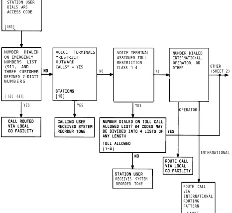
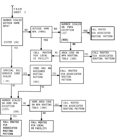
Automatic Route Selection Flow Chart
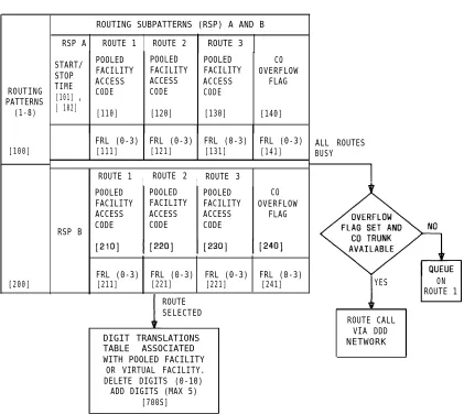
Automatic Route Selection Routing Pattern
T y p i c a l B r i d g i n g A r r a n g e m e n t
Call Accounting System —On-Premises Direct Connections (Sharing Same AC Outlet)
Call Accounting System— On-Premises Direct Connections (Greater Than 50 Feet From System Cabinet or Not Sharing Same AC Outlet)
Communications Access Manager Architecture
Asynchronous Data Unit Interface Signals
Dictation System Connections (FCC Registered)
Digital Tape Unit
Digital Tape Unit— On-Premises Direct Connections (Sharing Same AC Outlet)
Delay Announcement Equipment Connections (FCC Registered)
External Alert Connections
Supplemental Alert Adapter Connections
Stages of Call Forwarding
500A/502A/502B Headset Adapter
Typical Headset Adapter to 7300H Series Voice Terminal Connections Not Requiring Auxiliary Power
Typical Headset Adapter to 7300H Series Voice Terminal Connections Requiring Auxiliary Power
Typical Headset Adapter Connections For 12-Button MET Sets
Music-On-Hold Equipment Connections (FCC Registered)
Music-On-Hold Equipment Connections (Non-Registered)
2-187
2-224
2-253 2-254 2-255 2-276 Figure 2-31 Figure 2-32 Figure 2-33 Figure 2-34 Figure 2-35
10B Emergency Transfer Unit (ETU)
Emergency Transfer Unit Connections
Multiple ETU Arrangements
Speakerphone Adjuncts
Speakerphone Connections For 7300H Series Multiline Voice
Terminals (Except 34-Button Sets) 2-277
2-278
2-279
2-285 Speakerphone Connections For 34-Button Voice Terminals
Figure 2-36
Figure 2-37
Figure 2-38
Figure 2-39
Speakerphone Connections For 12-Button MET Sets
STARLAN NETWORK and System 25 Configuration
STARLAN NETWORK Connection to System 25 (With 2500
Single-Line Telephone) 2-289
Figure 2-40 STARLAN NETWORK Connection to System 25 (With ATL-Type
Telephone) 2-290 2-298 2-299 2-300 Figure 2-41 Figure 2-42 Figure 2-43 Figure 2-44
Typical SMDR Call Detail Report
SMDR Call Record Format
SMDR Call Record Header Format
SMDR Output Equipment—On-Premises Direct Connections
(Sharing Same AC Outlet) 2-301
Figure 2-45 SMDR Output Equipment— On-Premises Direct Connections (Greater Than 50 Feet From System Cabinet or Not Sharing
Same AC Outlet) 2-302
2-303
2-304
2-305
2-311
2-312 SMDR Output Equipment— On-Premises Switched Connections
Figure 2-46
Figure 2-47
Figure 2-48
Figure 2-49
Figure 2-50
Figure 2-51
SMDR Output Equipment— Off-Premises Direct Connections
SMDR Output Equipment—Off-Premises Switched Connections
Model 703 System Administration Terminal
SAT On-Premises Direct Connections (Sharing Same AC Outlet)
SAT On-Premises Direct Connections (Greater Than 50 Feet
From System Cabinet or Not Sharing Same AC Outlet) 2-313
2-314 2-315 2-316 Figure 2-52 Figure 2-53 Figure 2-54
SAT On-Premises Switched Connections
SAT Off-Premises Direct Connections
Table 2-A
Table 2-B
Table 2-C
Table 2-D
Table 2-E
Table 2-F
Table 2-G
Table 2-H
Table 2-I
Table 2-J
Table 2-K
Table 2-L
System Features
Station Features
Network Features
Data Features
Attendant Features
Bridged Ringing Options
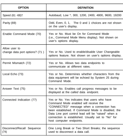
Partial List of Permissible Data Port (TN726) Options
Typical Option Profiles for Data Port Endpoints
Call Progress Messages for Data Terminal Dialing
Special Descriptors
LED lndications
User Changeable Options
2-3
2-4
2-5
2-6
2-7
2-68
2-99
2-100
2-126
2-152
2-207
FEATURES AND SERVICES
Introduction
This section describes the System Features, Station Features, Network Features, Data Features, and Attendant Features of AT&T System 25. It also covers certain services that support and implement the features; included in this category are the digital tape unit, the dial plan, system administration, and system maintenance. A general discussion of data topics is also provided.
The feature descriptions are arranged in alphabetical order, regardless of the feature group to which they belong. Information for each feature is presented under one or more of the following five subheadings: Description, Considerations,
Requirements, and Hardware Requirements. Headings that are
● Description
Defines the feature, describes what it does for the user,
● Considerations
Discusses the applications parameters and factors to be
● Interactions
●
●
Interactions, Administration not applicable are omitted.
and how it is used.
and benefits of the feature, followed by feature considered when the feature is used.
Lists and briefly describes other features that can affect the feature being described. Interacting features are those that:
— Depend on each other— One of the features must be provided if the other one is.
— Cannot coexist—One of the features cannot be provided if the other one is.
— Affect each other—The operation of one feature modifies, or is modified by, the operation of the other.
— Enhance each other—The features, in combination, provide improved service to the user.
Administration Requirements
States whether or not administration is required and lists items requiring administration.
Hardware Requirements
Symbols Used in Illustrations
Many feature descriptions in this section contain illustrations of equipment and connections. In the connection figures, modular jacks are shown as triangles; 25-pair cable connectors are indicated by shaded blocks. Unterminated wiring that requires cutdown or other termination does not have symbol designations. The 103A Connecting Block is a typical modular wall jack that provides cutdown connections for building (station) wiring.
Feature Tables
Tables 2-A through 2-E list all the features of System 25. Each feature is specified as Standard or Optional.
Standard features are built into the system. They are always provided but may require administration to make them operational. Standard features are identified in the feature tables by the letter S.
Optional features require both administration and additional equipment. Music-On-Hold is an example. Optional features are identified by the letter O.
System Features
System features (Table 2-A) are those that affect the entire operation of the system.
Table 2-A. System Features
FEATURE NAME FEATURE
T Y P E
Call Accounting System (CAS) O
Call Management System (CMS) O
Dial Plan
s
Dlctatlon System Access O
Digital Tape Unit O
Direct Group Calling S
Direct Group Calling Delay Announcement O
End-to-End Signaling S
Extended Stations O
External Alerts O
Integrated Solution O
Intercept Treatment With Reorder Tone S
Interdigit Timeouts S
Music-On-Hold O
Night Service (Directed and TAAS) S/O*
Night Service Delay Announcements O
Out-Of-Building Stations O
Paging System Access O
Personal Dial Codes S
Pooled Facility-Dial Access S
Power Failure Transfer O
Remote Administration Interface O
Remote Initialization and Maintenance Services (RIMS) S
Station Message Detail Recording (SMDR) O
System Administration O
System Maintenance S
Touch-Tone and Dial Pulse Service S
deice Message System O
Station Features
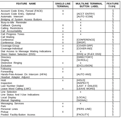
The many Station Features (Table 2-B) available allow individual user needs to be met. As these needs change, assigned features can also be changed. Station Features provide important services that help save time and make calling more convenient.
Table 2-B. Station Features
FEATURE NAME SINGLE-LINE MULTILINE TERMINAL FEATURE
TERMINAL BUTTON LABEL TYPE
Account Code Entry, Forced (FACE) x S
Account Code Entry, Optional x [ACCT ENTRY] S
Automatic Intercom [AUTO ICOM] S
Bridging of System Access Buttons x S
Busy-to-Idle Reminder x S
Callback Queuing x x S
Calling Restrictions x x S
Call Accountability x x S
Call Progress Tones x x S
Call Waiting x S
Conference x [CONFERENCE]
s
Conference Drop x [DROP] S
Coverage-Group x [COVER-GRP] S
Coverage-lndividual x [COVER-IND] S
Dial Access to Message Waiting Indications x Direct Station Selection (DSS)
x S
[DSS] or [FLEX DSS] S
Directory [DIRECTORY] O
Display [SCROLL] O
Distinctive Ringing x x S
Exclusion [EXCLUSION] S
Following x x S
Forwarding x S
Hands-Free-Answer On Intercom (HFAI) [AUTO ANS] O
Headset Adapter Adjunct x O
Hold x [HOLD] S
Inspection [INSPECT] O
Last Number Dialed [LAST # DIALED] S
Leave Word Calling (LWC) x [LEAVE WORD] O
Line Selection x
Line Status And l-Use Indications
S S
Local Display [LOCAL] O
Manual Signaling [SIGNAL] S
Messaging Services x x S
Park x S
Personal Lines [PERS LINE] S
Pickup x S
Pooled Facility-Button Access [FACILITY] S
Table 2-B. Station Features (Contd)
FEATURE NAME SINGLE-LINE MULTILINE TERMINAL FEATURE
TERMINAL BUTTON LABEL TYPE
Program x x S
Recall x S
Repertory Dialing [REP DIAL] S
Send All Calls [SEND ALL CALLS] S
Speaker (Spokesman Service) [SPEAKER] S
Speakerphone Adjunct x x O
Speed Dialing x x S
Station Hunting x S
Station-To-Station Message Waiting [MSG WAIT] S
Test S
Transfer x [TRANSFER] S
Trunk-To-Trunk Transfer x x S
Network Features
This group of features (Table 2-C) supports communications with the public network and with other locations in the private network of which System 25 can be a part.
Table 2-C. Network Features
FEATURE NAME FEATURE
TYPE
Automatic Route Selection S
Direct Inward Dialing O
Off-Premises Stations O
Remote Access S
Tandem Trunking O
Tie Trunks O
Trunk Groups S
Data Features
Data Features (Table 2-D) support the switched data services of the system. Data services provide switched connections between analog and digital data endpoints.
Table 2-D. Data Features
FEATURE NAME
I
MULTILINE TERMINAL BUTTON LABELCommand Mode
Communications Access Manager Data Call Setup
Data Terminal Dialing Expert Mode Modem Pooling
AT&T STARLAN NETWORK Access Third-Party Call Setup
Transfer to Data
User Changeable Options
[DATA]
FEATURE TYPE
Attendant Features
Attendant Features (Table 2-E) are available to the attendant using the Direct Trunk Attendant Console (DTAC) or the Switched Loop Attendant Console (SLAC) and the optional Direct Extension Selector Console. In addition, most muitiline voice terminal station features are available to the attendant.
Table 2-E. Attendant Features
FEATURE NAME CONSOLE BUTTON FEATURE
LABEL TYPE
Attendant Call Extending [START] S
Attendant Camp-On S
Attendant Cancel [CANCEL] S
Attendant Console, Direct Trunk O
Attendant Console, Switched Loop O
Attendant Direct Extension Selection O
Attendant Forced Release (SLAC only) [FORCED RELEASE] S
Attendant Join (SLAC only) [JOIN] S
Attendant Message Waiting (DTAC) [ATT MSG] S
Attendant Message Waiting (SLAC) [ATTENDANT
MESSAGE WAITING] S
Attendant Position Busy [POS BUSY] S
Attendant Release [RELEASE] S
Attendant Return-Coverage-on-Busy [RTN-BUSY]* S
Attendant Return-Coverage-on-Don’t-Answer [RTN-DA]* S
Attendant Source/Destination (SLAC only) [SOURCE], [DEST] S
Attendant Splitting One-Way Automatic S
Attendant System Alarm Indication [ALARM] S
Message Center-Like Operation (SLAC only) S
Night Service [NIGHT] S
Account Code Entry, Forced
Description
This feature forces selected station users to enter account codes before dialing certain calls out of System 25. Users at stations that have Forced Account Code Entry (FACE) are required to enter account codes either for all outgoing calls or for just “dial 0 or 1” toll calls. The code entries appear in the ACCOUNT field of the SMDR records.
To make a FACE-restricted call, the user must dial the Account Code Entry access code *0 followed by an account code before dialing the rest of the call. The account code entry is terminated when the number of digits entered equals the number administered for system account codes or when # is entered. The user hears second dial tone after the code is entered and can then dial the necessary access codes and other numbers to reach the destination.
If the user makes an error while entering the account code, the procedure can be corrected by dialing *0 followed by the correct account code.
The user receives reorder tone when an account code is required on a call but not entered.
Considerations
FACE ensures that specified outgoing calls include information (project, client, department, etc.) to be used for accounting and billing purposes.
The voice terminal user cannot use the Account Code Entry feature button for forced entry. This button is used with the Optional Account Code Entry feature only.
An account code entry cannot be forced for the following types of calls:
● Personal Line calls
● Direct Facility Access calls ● Remote Access
● Calls to 911 and the three ARS-administered emergency numbers, when using ARS. FACE requirements apply to calls using these facilities and features:
● Repertory Dialing
● Personal/System Speed Dialing
The system does not check the validity of account codes. It checks only for the proper number of digits or the code terminator #.
Calls that do not require FACE can still be assigned an account code, as in previous releases of System 25. Refer to the “Account Code Entry, Optional” feature description in this manual for the procedures.
Interactions
The following features interact with Forced Account Code Entry.
Bridging of System Access Buttons: Calls made from Bridged Access (BA) buttons on a
bridging station follow the FACE restrictions of the bridging station, not of the associated principal station.
Call Accountability: The account code entry may be made before or after the Call
Accountability entry. Dial tone is returned to the user after either entry.
Callback Queuing: An account code entered before queuing is saved for SMDR.
Conference: Calls can be conference in both directions between a FACE-restricted station
and a non-FACE station.
Display: When a user activates the Forced Account Code Entry feature by dialing *0, the
system displays the prompt ACCT?. As the user enters the account code, the digits are displayed to the right of the prompt. If the number of digits exceeds 9, the system automatically scrolls to Screen 2; the continuation character “-” and the remaining digits appear on Screen 2.
The prompt and digits remain displayed until one of the following occurs:
— The user enters either “#” or the administered number of code digits.
— The user restarts the Account Code Entry feature by dialing *0 to correct an erroneous entry.
— The system time-out for Account Code Entry is reached.
— The user selects another button that overwrites the display.
Forwarding: Stations with FACE administered for all calls cannot forward calls to any
outside numbers, Stations with FACE administered for “dial 0 or 1” calls can forward calls to any outside number except for “dial 0 or 1” numbers.
Intercept Treatment with Reorder Tone: The user receives reorder tone when an account
code is required on a call but is not entered.
Last Number Dialed: The access code *0 and the account code are not stored by this
Remote Access: Remote access callers cannot enter account codes.
Third-Party Call Setup: If the source station is FACE-restricted, the third-party data terminal
must prefix the outside destination number with *0 and an account code.
Transfer: Calls can be transferred in both directions between a FACE-restricted station and
a non-FACE station.
Administration Requirements
Account code entry is administered on a per-station basis— Optional, Forced for all Outgoing Calls, or Forced for Dial 0 or 1 Toll Calls Only; default = Optional.
Account Code Entry, Optional
Description
Optional Account Code Entry allows voice terminal users to associate an account code with incoming and outgoing calls. The account code is appended to the SMDR call record and can be used later for accounting or billing purposes.
For an incoming call, the user must enter the account code at the end of the call. For an outgoing call, the user has a choice of entering the code at the beginning of the call, before the destination is dialed, or at the end of the call. An account code entry is terminated when the number of digits entered equals the number administered for system account codes, when # is entered, or when the user hangs up. The procedures for associating an account code with a call are as follows:
● Single-Line Voice Terminal User
Get dial tone (by going off-hook at the beginning of a call or by flashing the switchhook before hanging up) and dial *0; then dial the account code directly or dial a System or Personal Speed Dialing Number that contains the account code. If the code is dialed incorrectly (before the last digit), redial *0 and the correct number.
● Multiline Voice Terminal User
At the beginning of an outgoing call, get dial tone and dial *0; then dial the account code directly or dial a System or Personal Speed Dialing Number that contains the account code. If the code is dialed incorrectly (before the last digit), redial *0 and the correct number. At the end of a call, press ACCT ENTRY and enter the code before hanging up. A Repertory Dialing (REP DIAL) button can also be used to enter an account code. If the code is dialed incorrectly (before the last digit), press ACCT ENTRY again and dial the correct number.
When the correct number of account code digits has been entered (or # is entered to signal end-of-dialing), confirmation tone is returned to the user, and the account code is appended to the SMDR call record.
Considerations
Optional Account Code Entry provides an easy method of allocating the costs of specific calls (and associated staff time) to the correct project, department or user. The account code is appended to the SMDR call record and sent to the SMDR output channel.
Account Codes can contain up to 15 digits.
The system does not check the validity of account codes. It only checks for the proper number of digits or the code terminator #.
Erroneous account codes that are not corrected before the last digit is entered are recorded and cannot be changed. Partial account codes entered by going on-hook before completing the entry are recorded and cannot be changed.
If, before all digits have been entered, (1) the user goes on-hook, (2) a button other than ACCT ENTRY is pressed, or (3) 30 seconds have elapsed since the feature was invoked, the SMDR call record will show the digits dialed up to that point.
Optional Account Code Entry cannot be invoked for a call on hold.
Interactions
The following features interact with Optional Account Code Entry.
Bridging of System Access Buttons: Account codes can be entered for incoming or outgoing calls on Bridged Access buttons using normal feature operations.
Callback Queuing: An account code entered before queuing is saved for SMDR.
Conference: If more than one user attempts to enter an account code on a Conference Call,
the first to enter a code will prevail.
Display: When a user activates the Account Code Entry feature by dialing *0 or pressing
ACCT ENTRY, the system displays the prompt ACCT?. As the user enters the account code, the digits are displayed to the right of the prompt. If the number of digits exceeds 9, the system automatically scrolls to Screen 2; the continuation character “-” and the remaining digits appear on Screen 2.
The prompt and digits remain displayed until one of the following occurs:
● The user enters either “#” or the administered number of code digits.
● The user restarts the Account Code Entry feature by dialing *0 or pressing ACCT ENTRY again, to correct an erroneous entry.
● The system time-out for Account Code Entry is reached. ● The user selects another button that overwrites the display.
Remote Access: Remote access callers cannot enter account codes.
Repertory Dialing: An account code can be stored on a REP DIAL button.
Speed Dialing: An account code can be stored in a System or Personal Speed Dialing code.
Transfer: A user can transfer a call to another user, then, before hanging up, enter an
Administration Requirements
System:
● Assign number of Account Code digits (0-15; default = 15). Voice Terminal Port:
● Multiline terminals—Assign Account Code Entry button. ● Single-line terminals—no administration required.
Hardware Requirements
Attendant Call Extending
Description
This feature allows the attendant to put a call in a special hold condition, call another station, then connect the two calls together. The attendant can withdraw from the connection and separate the call from the console or remain connected to the other parties. Attendant Call Extending is a feature used at either a Direct Trunk Attendant Console (DTAC) or a Switched Loop Attendant Console (SLAC).
Note: In general, the attendant should not use the TRANSFER button, which invokes the standard multiline voice terminal Transfer feature, to extend calls. If Transfer is used, busy or unanswered calls cannot return to the attendant console for further handling.
The attendant, after placing or answering a call, can use Procedure 1 or 2 to extend this call to an inside extension or Procedure 1 to extend it to an outside number:
1. Press START to place the incoming call on hold via the Attendant Splitting One-Way Automatic feature. After receiving Dial Tone, the attendant then dials the requested inside or outside number.
or
2. Press the Selector Console Group Select and Direct Extension Selection (DXS) buttons associated with the requested inside station. This operation is equivalent to pressing START and dialing the extension.
If ringing tone is heard, the attendant presses RELEASE (Manual Release) to connect the caller to the ringing line and separate the call from the console. As an alternative, a DTAC attendant or a SLAC attendant (with Automatic Release administered) can go straight to another call by pressing any facility button, such as System Access, Loop, Automatic Intercom, or an outside line; this completes the call extending procedure. (if a SLAC attendant has Automatic Hold administered instead of Automatic Release, pressing a facility button simply puts the incoming call on hold and does not extend it.)
The attendant has the option of staying connected to the ringing line to announce the call before connecting the two parties. The attendant can then release or (SLAC only) join the other parties in a 3-way connection by using the Attendant Join feature.
If busy tone is heard and Attendant Camp-On (see associated feature description) is not desired, the attendant presses CANCEL and is reconnected to the calling party.
Calls extended to an idle voice terminal that are not answered within a specified time return to the Attendant Console on an idle LOOP button (SLAC only) or on the Return-On-Don’t-Answer (RTN-DA) button (DTAC only). Calls camped-on at a busy voice terminal that are not answered within a specified time return to the Attendant Console on an idle LOOP button (SLAC only) or on the Return-On-Busy (RTN-BUSY) button (DTAC only). If a SLAC is not available to incoming calls (busy on another call, in Position Busy mode, etc.), a returning call remains in the console queue until the console can handle it. If the Return buttons on a DTAC are busy, an extended call remains at the called terminal until that button becomes idle.
Considerations
Attendant Call Extending allows the attendant to utilize the additional attendant related features such as Attendant Splitting One-Way, Release, Cancel, Return-On-Don’t-Answer, Return-On-Busy, Forced Release (SLAC), Join (SLAC), and Source/Destination (SLAC).
For information on related Attendant Features (Table 2-E), refer to the individual feature descriptions.
Interactions
The following feature interacts with Attendant Call Extending.
Forwarding: Calls extended by an attendant to a forwarding station will be given normal
Forwarding treatment.
Administration Requirements
System:
● Number of seconds before a Camped-On call returns to the Attendant Console (1-120 or 0 for no Attendant Camp-On; default = 30).
Attendant Camp-On
Description
This feature allows the attendant to extend a trunk call to a busy voice terminal and leave it waiting or “camped on” there. After hearing busy tone, the attendant presses RELEASE to camp-on this call at the busy terminal. When this is done, a burst of tone is heard in the handset of the called terminal and the caller is placed on hold (hearing music-on-hold if available). When a System Access button at a multiline set becomes idle or a single-line terminal hangs up, the camped-on call is connected automatically and ringing begins.
Considerations
A camped-on call can be answered by a busy single-line user without losing the current call by momentarily pressing the switchhook (which places the current call on hold) and then dialing *9. Multiline terminal users cannot do this. However, if they have a System Access-Originate Only button, they can place all other calls on hold, go off-hook on that button and dial *9 to pick up the camped-on call.
If the camped-on call is not answered within a specified time, the call will be returned to the Attendant Console in one of the following ways:
● Switched Loop Attendant Console
The call returns to the common queue, where it remains until the console can receive it at a LOOP button.
● Direct Trunk Attendant Console
The call returns to the Return-On-Busy (RTN-BUSY) button. If that button is busy, the call remains camped-on at the called terminal until the RTN-BUSY button of the console becomes idle.
For information on related Attendant Features (Table 2-E), refer to the individual feature descriptions.
Interactions
The following features interact with Attendant Camp-On.
Call Waiting: Trunk calls camped onto a station by an attendant are given priority over other
waiting calls.
Callback Queuing: Trunk calls camped onto a station by an attendant are given priority over
queued calls.
Coverage: If the called party is a sender in a Coverage group and all receivers of the
Direct Group Calling: The attendant can camp-on more than one call per DGC group. Voice
terminals in the group do not receive a burst of tone when a call is camped on. Trunk calls camped onto a busy DGC group go into the DGC queue and are eligible for delay announcement and music-on-hold.
Direct Inward Dialing (DID): DID calls can be covered by the attendant and then given
Camp-On treatment. They do not automatically receive Call Waiting.
Station Hunting: If the called party is a member of a hunt group and all members of the
group are busy, the call camps onto the originally-dialed station. Once camped-on, calls will no longer hunt even if another member of the hunt group becomes idle.
Administration Requirements
System:
Attendant Cancel
Description
This feature allows the attendant to terminate an attempt to extend any incoming call if the called station does not answer, or if the station answers but declines to accept the call. The attendant presses CANCEL and is automatically reconnected to the calling party. The call can then be ended by hanging up or by pressing RELEASE.
Pressing CANCEL when the Start facility is not active will be ignored.
Considerations
Attendant Cancel allows the attendant to terminate a call transfer incoming held party via a one-button operation. This enhances handle calls quickly and efficiently.
Attendant
Description
In System 25
Console, Direct Trunk
the Attendant Console is used to answer incoming trunk calls that are not directed to specific user stations, to answer calls from inside users, to extend calls to inside stations and outside numbers, and to assist system users in placing outgoing calls and setting up conferences. The attendant can also manage and monitor some areas of system operation. System 25 supports either the Direct Trunk Attendant Console (DTAC) or the Switched Loop Attendant Console (SLAC), which is covered in the next feature description in this manual. Consoles of both types cannot be installed in the same system.
The DTAC (Figure 2-1) can be one of the Merlin Communications System multiline voice terminals listed below, administered with special features, buttons, and capabilities to serve as an attendant position.
● 7305H02D (34 programmable feature buttons each with I-use and status LEDs) ● 7305H03B (34 programmable feature buttons; built-in speakerphone)
● 7316H01A (34 programmable feature buttons each with I-use and status LEDs; built-in speakerphone)
In addition to the attendant features, most standard multiline terminal features are also available. (Refer to the Hardware Description section of this manual for a complete identification of the external controls, indicators, and components of the DTAC voice terminal.)
DIRECT TRUNK ATTENDANT OPTIONAL SELECTOR
CONSOLE CONSOLE
Figure 2-1. Typical Direct Trunk Attendant Console Position
● Start [START]: Initiates the call extending process by placing a cal