User Manual
Part Number 1200180L1
Part Number 1200227L1
DMS 100 is a registered trademark of Northern Telecom. 5ESS is a registered trademark of AT&T.
AT&T is a registered trademark.
901 Explorer Boulevard P.O. Box 140000 Huntsville, AL 35814-4000
(256) 963-8000 © 1999 ADTRAN, Inc.
ADTRAN has established a Year 2000 program to ensure that our products will correctly function in the new millennium. ADTRAN warrants that all products meet Year 2000 specifications regardless of model or revision. Information about ADTRAN's Year 2000 compliance program is available at the fol-lowing:
Product Matrix www.adtran.com/y2kfax.html
E-mail [email protected]
Faxback Document Line (256) 963-8200
Y2K plans and product certifications are listed in the Product Matrix (see above)
1. This equipment complies with Part 68 of the FCC rules. The required label is affixed to the bottom of the chassis.
2. An FCC-compliant telephone cord and modular plug is provided with this equipment. This equip-ment is designed to be connected to the telephone network or premises wiring using a compatible modular jack which is Part 68-compliant. See Chapter 2, Installing the ATLAS 800, for details. 3. If your telephone equipment (ATLAS) causes harm to the telephone network, the telephone
com-pany may discontinue your service temporarily. If possible, they will notify you in advance. But if advance notice isn’t practical, you will be notified as soon as possible. You will be advised of your right to file a complaint with the FCC.
4. Your telephone company may make changes in its facilities, equipment, operations, or procedures that could affect the proper operation of your equipment. If they do, you will be given advance notice to give you an opportunity to maintain uninterrupted service.
5. If you experience trouble with this equipment (ATLAS), please contact ADTRAN at (256) 963-8000 for repair/ warranty information. The telephone company may ask you to disconnect this equip-ment from the network until the problem has been corrected or until you are sure the equipequip-ment is not malfunctioning.
6. This unit contains no user-serviceable parts.
7. The following information may be required when applying to your local telephone company for leased line facilities.
Service Type REN/SOC FIC USOC
1.544 Mbps - SF 6.0N 04DU9-BN RJ-48C
1.544 Mbps - SF and B8ZS 6.0N 04DU9-DN RJ-48C
1.544 Mbps - ESF 6.0N 04DU9-1KN RJ-48C
1.544 Mbps - ESF and B8ZS 6.0N 04DU9-1SN RJ-48C
This equipment has been tested and found to comply with the limits for a Class A digital device, pur-suant to Part 15 of the FCC Rules. These limits are designed to provide reasonable protection against harmful interference when the equipment is operated in a commercial environment. This equipment generates, uses, and can radiate radio frequency energy and, if not installed and used in accordance with the instruction manual, may cause harmful interference to radio frequencies. Operation of this equipment in a residential area is likely to cause harmful interference in which case the user will be required to correct the interference at his own expense.
Shielded cables must be used with this unit to ensure compliance with Class A FCC limits.
• An affidavit is required to be given to the telephone company whenever digital terminal equipment without encoded analog content and billing protection is used to transmit digital signals contain-ing encoded analog content which are intended for eventual conversion into voiceband analog sig-nals and transmitted on the network.
• The affidavit shall affirm that either no encoded analog content or billing information is being transmitted or that the output of the device meets Part 68 encoded analog content or billing protec-tion specificaprotec-tions.
• End user/customer will be responsible for filing an affidavit with the local exchange carrier when connecting unprotected customer premise equipment (CPE) to 1.544 Mbps or subrate digital ser-vices.
For the work to be performed in the certified territory of ________________________(telco name) State of ________________
County of ________________
I, _____________________________ (name), __________________________________(business address), ____________________ (telephone number) being duly sworn, state:
I have responsibility for the operation and maintenance of the terminal equipment to be connected to 1.544 Mbps and/or ________ subrate digital services. The terminal equipment to be connected com-plies with Part 68 of the FCC rules except for the encoded analog content and billing protection speci-fications. With respect to encoded analog content and billing protection:
( ) I attest that all operations associated with the establishment, maintenance, and adjustment of the digital CPE with respect to analog content and encoded billing protection information continu-ously complies with Part 68 of the FCC Rules and Regulations.
( ) The digital CPE does not transmit digital signals containing encoded analog content or billing information which is intended to be decoded within the telecommunications network.
( ) The encoded analog content and billing protection is factory set and is not under the control of the customer.
I attest that the operator(s)/maintainer(s) of the digital CPE responsible for the establishment, mainte-nance, and adjustment of the encoded analog content and billing information has (have) been trained to perform these functions by successfully having completed one of the following (check appropriate blocks):
( ) A. A training course provided by the manufacturer/grantee of the equipment used to encode analog signals; or
( ) B. A training course provided by the customer or authorized representative, using training mate-rials and instructions provided by the manufacturer/grantee of the equipment used to encode analog signals; or
( ) C. An independent training course (e.g., trade school or technical institution) recognized by the manufacturer/grantee of the equipment used to encode analog signals; or
_________________________________Signature _________________________________Title _________________________________ Date Transcribed and sworn to before me This ________ day of ________, 199___ _________________________________ Notary Public
My commission expires:
Before installing this equipment, users should ensure that it is permissible to be connected to the facil-ities of the local telecommunications company. The equipment must also be installed using an accept-able method of connection. In some cases, the company's inside wiring associated with a single line individual service may be extended by means of a certified connector assembly (telephone extension cord). The customer should be aware that compliance with the above conditions may not prevent deg-radation of service in some situations.
Repairs to certified equipment should be made by an authorized Canadian maintenance facility desig-nated by the supplier. Any repairs or alterations made by the user to this equipment, or equipment malfunctions, may give the telecommunications company cause to request the user to disconnect the equipment.
Users should ensure for their own protection that the electrical ground connections of the power util-ity, telephone lines and internal metallic waterpipe system, if present, are connected together. This precaution may be particularly important in rural areas.
The Load Number (LN) assigned to each terminal device denotes the percentage of the total load to be connected to a telephone loop which is used by the device, to prevent overloading. The termination on a loop may consist of any combination of devices subject only to the equipment that the total of the LNs of all devices does not exceed 100.
The ringer equivalence number (REN) assigned to each terminal adapter is used to determine the total number of devices that may be connected to each circuit. The sum of the RENs from all devices in the circuit should not exceed a total of 5.0.
The Industry Canada Certification label identifies certified equipment. This certification means that the equipment meets certain telecommunications network protective, operational, and safety requirements. The Department does not guarantee the equipment will operate to the user's satisfaction.
The ATLAS_800 system consists of the Base Unit and one or more option modules. (Each option mod-ule includes its own user manual which contains specific information about installing, configuring, and testing the option module; insert the option module manuals into this binder.) This ATLAS User Manual provides the information you need to install, configure, test, and troubleshoot the ATLAS_800 system; when applicable, this manual refers you to the individual option module user manual. The arrangement of this user manual allows you to quickly and easily find the information you need. An overview of the contents of this manual follows:
Introduction
• Chapter 1, Introducing the ATLAS 800, familiarizes you with the ATLAS_800 Base Unit and provides some sample ATLAS_800 applications.
Getting Started
• Chapter 2, Installing the ATLAS 800, describes the rear panel layout and how to install the ATLAS_800.
• Chapter 3, Operating the ATLAS 800, describes the front panel layout and different ways to operate the ATLAS_800.
Reference Information
• Chapter 4, Using the Front Panel, describes how to use the front panel. This chapter also describes each menu option that is accessible through the front panel.
• Chapter 5, Navigating the Terminal Menu, describes how to navigate the terminal menu.
• Chapter 6, Terminal Menu and System Control, describes the terminal menus used for system control. • Chapter 7, Modules Terminal Menu, describes the terminal menus used for module and T1/PRI port
control.
• Chapter 8, Dedicated Maps Terminal Menu, describes the terminal menus used for Dedicated Maps and provides some examples.
• Chapter 9, Dial Plan Terminal Menu, describes the terminal menus used for Dial Plans and provides some examples.
Working with the ATLAS_800
• Chapter 10, Updating Firmware, provides step-by-step instruction on how to update the ATLAS_800 firmware.
• Chapter 11, SNMP Management, describes how to control the ATLAS_800 via SNMP.
• Chapter 12, ADTRAN Utilities, describes the SysLog, Telnet, VT-100, and TFTP Server programs de-livered with the ATLAS_800.
Appendices
• Appendix A, System Event Logging, describes the events monitored by the ATLAS_800.
• Appendix B, Troubleshooting, describes how to diagnose different problems you may experience. • Appendix C, Warranty and Technical Support Information, describes your warranty and how to
con-tact technical support.
• Appendix D, Acronyms and Abbreviations, lists acronyms and abbreviations used for the ATLAS 800 and its option modules.
Cautions signify information that could prevent service interruptions.
List of Figures ... xix
List of Tables... xxi
Chapter 1 Introducing the ATLAS 800 ... 1-1
Product Overview ...1-1 ATLAS_800 Base Unit ...1-1 ATLAS_800 Features ...1-5
Chapter 2 Installing the ATLAS 800 ... 2-1
Inspect the ADTRAN Shipment ...2-1 Contents of ADTRAN Shipments ...2-1 Check the Power Connection ...2-1 AC Powered Unit ...2-2 DC Powered Unit ...2-2 Grounding Instructions ...2-2 Review the Rear Panel Design ...2-3 Control/Chain In Port ...2-4 Connection... 2-4 Control/Chain Out Port ...2-5 Connection... 2-5 Network Connection ...2-6 Connection... 2-6 10BaseT Ethernet Connection ...2-6 Connection... 2-6 MON ...2-7 Option Slots ...2-7 Install Any Option Modules ...2-7 Power-Up ...2-8
Chapter 3 Operating the ATLAS 800 ... 3-1
Methods of Operating the ATLAS 800 ...3-1 Using the Front Panel ...3-1 Using the Terminal Menu ...3-2 Using Telnet ...3-3 Starting a Telnet Session ... 3-4 Using VT-100 Terminal Emulation ...3-4 Using T-Watch PRO ...3-5
Chapter 4 Using the Front Panel ... 4-1
Status... 4-7 S0 System ... 4-7 S1—S8 ... 4-7 Config... 4-7 S0 System ... 4-7 S1—S8 ... 4-9 Util ... 4-9 Time/Date ... 4-9 Software Rev ... 4-9 Selftest ... 4-10 Set Passcode ... 4-11 Password Reset ... 4-11 ALRM Menu ... 4-11 Active Alarms ... 4-11 View History ... 4-12 Clear History ... 4-12
Chapter 5 Navigating the Terminal Menu ... 5-1
Terminal Menu Window ... 5-1 Menu Path ... 5-1 Window Panes ... 5-2 Window Pane Navigation ... 5-2 Right Window Pane Notation... 5-2 Additional Terminal Menu Window Features ... 5-3 Navigating Using the Keyboard Keys ... 5-3 Moving through the Menus ... 5-3 Session Management Keystrokes ... 5-4 Configuration Keystrokes ... 5-4 Getting Help ... 5-5
Chapter 6 Terminal Menu and System Control ... 6-1
Chain Port Rx Bytes ...6-6 Chain Port Overrun Errs ...6-6 Chain Port Framing Errs ...6-6 Clear Chain Port Countrs ...6-6 System Config... 6-6 Primary Timing Source ...6-7 Backup Timing Source ...6-7 ADLP Address ...6-7 Session Timeout ...6-7 Max Telnet Sessions ...6-7 Ethernet Port ...6-8 Chain Port ...6-8 SNMP ...6-9 System Event Logging ...6-10 Syslog Setup ...6-10 Real Time Clock ...6-10 Access Passwords ...6-11 System Utility ... 6-12 Update Firmware ...6-12 Update Status ...6-15 Config Transfer ...6-15 System Utilization ...6-16 System Selftest ...6-16 Ping ...6-17 Reboot System ...6-18 Factory Default System ...6-18
Chapter 7 Modules Terminal Menu... 7-1
Menus ... 7-1 Submenus ...7-1 Modules ... 7-1 Slt ...7-1 Type ...7-1 Menu ...7-2 Alarm ...7-2 Test ...7-2 State ...7-2 Status ...7-3 Rev ...7-3 Modules (T1/PRI) Menu ...7-3
Chapter 8 Dedicated Maps Terminal Menu ... 8-1
Designing the Dedicated Map for Example 2 ... 8-6 Configuring the Ports for Example 2 ... 8-7 Defining the Connections for Example 2 ... 8-8
Chapter 9 Dial Plan Terminal Menu ... 9-1
Overview ... 9-1 Network Term ... 9-2 # ... 9-3 Slot ... 9-3 Port ... 9-3 Sig ... 9-3 Out#Accept ... 9-3 Out#Rej ... 9-4 Ifce Config ... 9-5 User Term ... 9-5 Slot/Svc ... 9-5 Port/Link ... 9-5 Sig ... 9-5 In#Accept ... 9-5 Out#Rej ... 9-7 Ifce Config ... 9-7 Global Param ... 9-7 End of Number Timeout ... 9-7 Area Code ... 9-7 Nbr Complete Templates ... 9-8 Number Type Templates ... 9-8 Automatic Routeback Rejection ... 9-9 Quad T1/PRI Interface Configuration ... 9-9 Network Termination/PRI ... 9-9 Network Termination/RBS ... 9-13 User Termination/PRI ... 9-15 User Termination/RBS ... 9-17 Creating Dial Plans—Examples ... 9-19 Understanding Dial Plan Configurations ... 9-20
Chapter 10 Updating Firmware ... 10-1
Overview ... 10-1 XMODEM Firmware Updates ... 10-1 Updating Firmware using XMODEM ... 10-2 TFTP Firmware Updates ... 10-4 Updating Firmware using TFTP ... 10-4
Chapter 11 SNMP Management... 11-1
DS1 Alarm Traps ... 11-3 DS1 Alert Traps... 11-4
Chapter 12 ADTRAN Utilities ... 12-1
TFTP Server ... 12-9 Server Menu ... 12-11 Enable ... 12-11 Disable ... 12-11 Abort ... 12-11 Exit ... 12-11 Print Log ... 12-11 ...to Clipboard ... 12-11 ...to Printer ... 12-11 Clear Log ... 12-11 Help... 12-11 Contents ... 12-11 About ... 12-11 Status Field ... 12-11 Meter Field ... 12-11 Log Field ... 12-11 Saving the Current Configuration to a TFTP Server ... 12-12 Successful Transfer ... 12-12 Unsuccessful Transfer ... 12-13 Retrieving the Configuration from a TFTP Server ... 12-13
Appendix A System Event Logging ... A-1
Appendix B Troubleshooting ...B-1
Appendix C Warranty and Technical Support Information ...C-1
Appendix D Acronyms and Abbreviations ... D-1
Appendix E Glossary ... E-1
PRODUCT OVERVIEW
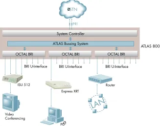
The ATLAS_800 is a modular, highly scalable platform that provides robust solutions for the wide-area communication needs of medium-to-large cor-porations and network access providers. ATLAS is an Integrated Access Sys-tem with the most extensive support of dedicated bandwidth management and access switching in the industry.
With the ATLAS_800 you can consolidate your voice, data, and video appli-cations into a single platform while optimizing wide-area bandwidth and re-ducing equipment costs. The ATLAS 800’s architecture and the chassis’ eight expansion slots allow you to select a variety of option modules, making the ATLAS_800 one of the most versatile access systems on the market. With the appropriate modules installed, the ATLAS_800 functions as follows: • A Digital Access Cross-Connect System (DACS)
• A T1 Bandwidth Manager • An ISDN Access Switch
ATLAS
_800 BASE UNIT
The ATLAS_800 architecture includes a packet switching and a circuit switching bussing scheme resulting in a highly scalable system capable of supporting bandwidth requirements of up to 34 T1/E1 or Primary Rate ISDN (PRI) circuits. Designed for standalone or rackmount installations, the ATLAS_800 Base Unit contains two network interfaces, each independently configurable for T1, DSX-1, or PRI operation. A 10BaseT Ethernet connection for remote access and network management is standard with the
ATLAS_800 Base Unit. The eight expansion slots accommodate hot-swappa-ble option modules for a variety of applications. ATLAS_800 option mod-ules include the following:
• Quad T1/PRI Module
• Octal Basic Rate ISDN Module • Quad Nx 56/64 Module • T3 Module
Dedicated and Switched Connection Maps in a Single Platform
The ATLAS_800 allocates dedicated bandwidth as directed by any of up to five unique connection maps. You can map any DS0 on any T1 circuit to any other DS0 on up to 34 T1 circuits in the system. Dedicated connection maps can be manually invoked or automatically implemented based on the time of day and day of the week.
Additionally, you can configure the ATLAS_800 to switch dialup calls to specific ports or DS0s based on the number dialed. The ATLAS_800 supports switched connection mapping for dial calls placed over Basic Rate ISDN (BRI), Primary Rate ISDN (PRI), or channelized T1 circuits.
Signaling Conversion for Maximum Interoperability
The ATLAS_800 converts between robbed bit signaling (RBS) and ISDN D channel signaling, giving you the speed and reliability of ISDN while pre-serving your investment in non-ISDN equipment. ATLAS also converts be-tween D4 and ESF frame formats as well as AMI and B8ZS line coding, providing interoperability with legacy equipment.
Flexible Network Management and Maintainability
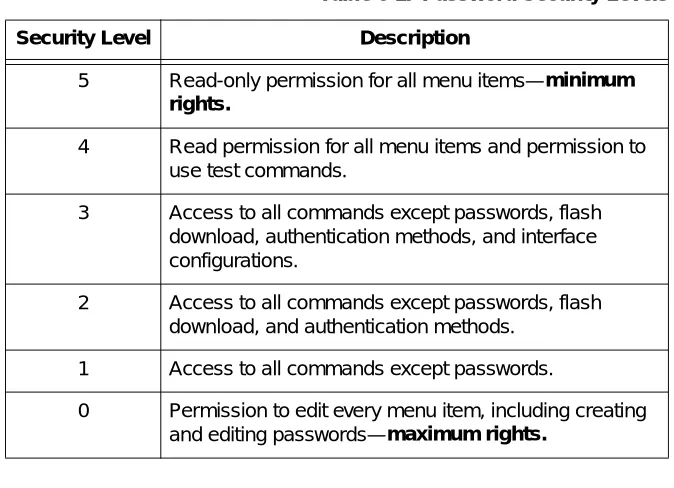
You can select from a variety of network management methods, including Simple Network Management Protocol (SNMP) support, VT-100 terminal emulation, and Telnet sessions. VT-100 terminal emulation and Telnet ses-sions provide detailed system configuration through an easy-to-use menu system. Six levels of password protection with varying degrees of manage-ment privileges secure the terminal interface. You can access the terminal in-terface locally or remotely using either the EIA-232 Chain-In port on the rear of the Base Unit or the Telnet interface. The 10BaseT Ethernet interface on the Base Unit provides an Ethernet connection for SNMP and Telnet connec-tions.
In addition, you can use T-Watch PRO, ADTRAN’s Microsoft® Windows™ based GUI management system, which provides end-to-end management for downstream ADTRAN T1 products. Nonvolatile memory preserves and duplicates user configurations for managing multiple ATLAS implementa-tions. ATLAS also supports flash upgrades for future enhancements. You can download software remotely using TFTP or XMODEM.
You can also use the front panel to manage the ATLAS_800. The front panel contains a 2x16 character backlit LCD display and an extensive array of LEDs for alarm and status information pertaining to the system and the in-dividual modules. The Front Panel keypad allows you to navigate through the menu system and to access system testing.
Digital Access Cross-Connect System (DACS)
Inherent in the ATLAS_800 architecture is the ability to cross connect, or DACS, up to 34 T1 circuits (see Figure 1-1). DACSing assigns and redistrib-utes, or grooms, any DS0 on any T1 circuit to any other DS0 on any of the 34 T1 circuits in the system. To optimize network resources, any of five dedi-cated connection maps can be invoked manually or automatically based on the time of day and day of the week.
Figure 1-1. Digital Access Cross-Connect System (DACS)
T1 Bandwidth Manager
As a T1 bandwidth manager, ATLAS_800 combines the functions of a T1 CSU/DSU, an intelligent channel bank, a T1 multiplexer and DACS into a single platform (see Figure 1-2). The bandwidth manager supports a wide range of data applications including T1 “drop and insert,” channel groom-ing, and wide area data transport. ATLAS is ideal for point-to-point config-urations or for access to public networks. To optimize existing equipment and network resources, you can pair ATLAS with ADTRAN’s TSU products to support a variety of data and analog voice applications.
Figure 1-2. T1 Bandwidth Management
T1 T1
Network
T1/FT1 T1/FT1 Remote
Locations Remote
Locations
System Controller Quad T1/PRI
ATLAS Bussing System
Quad T1/PRI Quad Nx 56/64 Quad Nx 56/64
ATLAS 800
ISDN Access Switch
The ATLAS_800 includes an advanced access architecture for switching dial-up calls to specific ports or DS0s. As an access switch functioning in a user-to-user network and user-to-user mode, ATLAS consolidates multiple BRI connections onto T1/PRI access lines. Additionally, ATLAS supports BRI-to-BRI, BRI-to-PRI, and PRI-to-PRI switching. ATLAS also converts be-tween ISDN D channel (PRI or BRI) and T1 RBS, allowing a non-ISDN PBX to access a more efficient ISDN facility. When bandwidth is unused for switched applications such as video conferencing, switched connection mapping dynamically allocates bandwidth to the PBX for voice traffic to op-timize the network. Call Filtering allows you to program the call types an-swered or originated on a per-user basis.
Wide Area Network (WAN) Overbooking
ATLAS_800’s WAN Overbooking feature allows you to oversubscribe switched bandwidth for situations where simultaneous access to the net-work by every subscriber is not required (see Figure 1-3). WAN Overbook-ing reduces telecommunications expenses while still givOverbook-ing your subscriber base the connectivity they require. Local subscriber-to-subscriber connec-tions are made without accessing the network at all, resulting in even more efficient use of wide-area bandwidth.
ATLAS
_800 FEATURES
Configuration and Management
• VT-100 Emulation
• T-Watch PRO, Microsoft Windows-based GUI
• SNMP, per MIB II (RFC1213), DS1 MIB (RFC1406), and ADTRAN pri-vate MIBs
• Telnet
• LCD front panel
• Six levels of password protection and privileges
Software Upgrade
• Flash memory • TFTP download
• XMODEM via control port
Signaling Support
• ISDN D channel
• Robbed bit signaling, E&M, Ground Start, Loop Start
• Converts between robbed bit signaling and ISDN D Channel • Direct inward dialing
ISDN Switch Types
• 5ESS™, DMS-100™, National ISDN
Dedicated Connection Maps
• Up to five connection maps
• Time of day/day of week configurable • Preserves signaling through cross-connect • No effect on nonconfigured channels
Switched Connection Maps
• Inbound and outbound call filtering and blocking
Testing
• Local and remote: payload/line, V.54 • Patterns: 511, QRSS, all ones, all zeros
Performance Monitoring
INSPECT THE ADTRAN SHIPMENT
Before installing the ATLAS 800, carefully inspect the ATLAS_800 Base Unit for shipping damage. If you suspect damage, file a claim immediately with the carrier and then contact ADTRAN Customer and Product Service (see Warranty and Technical Support Information on page C-1). If possible, keep the original shipping container for returning the ATLAS_800 for repair or for verification of damage during shipment.
Contents of ADTRAN Shipments
Your ADTRAN shipment includes the following items: • The ATLAS_800 Base Unit
• The ATLAS_800 User Manual
• Power cord (for 1200180L1 only) ADTRAN P/N 3127031 • Network cables (2) ADTRAN P/N 3125M008
• Rackmount brackets (left and right) • RJ45—DB25 adapter (modem and direct) • RJ45—DB9 adapter
• RJ45 control port cable (1) ADTRAN P/N 3127004 • DSX-1 crossover cable (1) ADTRAN P/N 3125M010 • RJ48—DB15 adapter (1)
• ADTRAN Utilities diskettes (3)
CHECK THE POWER CONNECTION
Check the power connection as appropriate to your power supply (AC or DC).
AC Powered Unit
The AC powered ATLAS_800 (P/N 1200180L1) comes equipped with a de-tachable 8-foot power cord with a three-prong plug for connecting to a grounded power receptacle.
DC Powered Unit
The DC powered ATLAS_800 (P/N 1200227L1) comes equipped with a ter-minal block on the rear of the unit. The power source should be connected to the terminal block according to the polarity markings on the unit. For ex-ample, a -48 V source would be connected to the unit with the -48 V return attached to the (+) terminal and the -48 VDC attached to the (-) terminal. Power must be from a DC power source in the range of 42 to 57 VDC, capa-ble of delivering up to 7 A of current.
The
Grounding Instructions
This section provides grounding instruction information from the Under-writers' Laboratory UL 1459 Standard for Safety: Telephone Equipment, of September 20, 1993.
An equipment grounding conductor that is not smaller in size than the un-grounded branch-circuit supply conductors is to be installed as part of the circuit that supplies the product or system. Bare, covered, or insulated grounding conductors are acceptable. Individually covered or insulated equipment grounding conductors shall have a continuous outer finish that is either green, or green with one or more yellow stripes. The equipment grounding conductor is to be connected to ground at the service equipment. The attachment-plug receptacles in the vicinity of the product or system are all to be of a grounding type, and the equipment grounding conductors serv-ing these receptacles are to be connected to earth ground at the service equipment.
A supplementary equipment grounding conductor shall be installed be-tween the product or system and ground that is in addition to the equipment
Power to the ATLAS_800 must be from a grounded 115 VAC, 60 Hz or a 220 VAC, 50-60 Hz source.
The branch circuit overcurrent protection shall be a fuse or circuit breaker rated minimum 48 V, maximum 20A.
The supplementary equipment grounding conductor shall not be smaller in size than the ungrounded branch-circuit supply conductors. The supple-mentary equipment grounding conductor shall be connected to the product at the terminal provided, and shall be connected to ground in a manner that will retain the ground connection when the product is unplugged from the receptacle. The connection to ground of the supplementary equipment grounding conductor shall be in compliance with the rules for terminating bonding jumpers at Part K or Article 250 of the National Electrical Code, ANSI/NFPA 70. Termination of the supplementary equipment grounding conductor is permitted to be made to building steel, to a metal electrical race-way system, or to any grounded item that is permanently and reliably con-nected to the electrical service equipment ground.
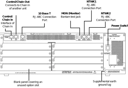
REVIEW THE REAR PANEL DESIGN
The rear panel of the ATLAS_800 contains eight slots for housing option modules which provide a variety of additional resources and data ports. See Figure 2-1 (AC-powered unit) and Figure 2-2 (DC-powered unit). All slots are functionally identical, except slots 7 and 8. These two slots can also ac-commodate an optional power supply for redundancy.
Figure 2-1. AC Powered ATLAS_800 Rear Panel
4A/25OV SLOBLO
I
O CONTROL
/CHAIN
IN OUT 10 BASE T MON NTWK 1 NTWK 2
CAUTION:
CAUTION: FOR CONTINUED PROTECTION AGAINST RISK OF FIRE REPLACE ONLY WITH SAME TYPE AND RATING OF FUSE.
1 2 3 4 5 6 7 8 90-130/190-240VAC 4A/2A, 50/60 HZ CAUTION: MAINTENANCE TO BE PERFORMED BY TRAINED SERVICE PERSONNEL ONLY
REMOVE POWER CORD PRIOR TO
ALL EMPTY SLOTS MUST BE COVERED WITH BLANK PANELS
CAUTION-RISK OF ELECTRIC SHOCK
SUPPLAMENTAL EARTH GROUND MUST BE CONNECTED PRIOR TO CONNECTION OF TELECOMMUNICATION WIRING
REMOVAL OF POWER SUPPLY
Power Switch
Blank panel covering an unused option slot Control/
Chain In Interface of
Chain In
Control/Chain Out Connects to Chain In
of another unit
10 Base T RJ-48C Connection
Port
MON (Monitor) Bantam test jack
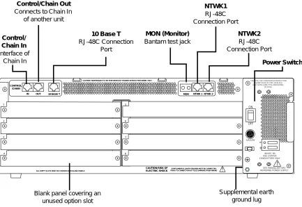
Figure 2-2. DC Powered ATLAS 800 Rear Panel
Control/Chain In Port
The Control/Chain In port (EIA-232) connects the ATLAS_800 to a comput-er or modem (Control In) or to anothcomput-er ATLAS_800 Base Unit (Chain In). The Control/Chain In port input does the following:
• Accepts EIA-232 input from a PC or a modem to control the ATLAS_800. • Attaches to another ATLAS 800 (chain input).
• Operates at 9600 or 2400 bps.
• Acts as input for PC control or as input for a chained connection. • Acts as an interface for flash memory software downloads using
XMODEM.
Connection
The Control/Chain In connection follows, with the pinout shown in Table 2-1.
Connector type RJ-48C
Part number AMP#555164-2 CONTROL
/CHAIN
IN OUT 10 BASE T MON NTWK 1 NTWK 2
1 2 3 4 5 6 7 8
CAUTION: MAINTENANCE TO BE PERFORMED BY TRAINED SERVICE PERSONNEL ONLY
ALL EMPTY SLOTS MUST BE COVERED WITH BLANK PANELS
CAUTION-RISK OF ELECTRIC SHOCK
SUPPLAMENTAL EARTH GROUND MUST BE CONNECTED PRIOR TO CONNECTION OF TELECOMMUNICATION WIRING
CAUTION: FOR CONTINUTED PROTECTION AGAINST RISK OF FIRE, REPLACE ONLY WITH SAME TYPE AND RATING
OF FUSE.
12A/125V
-+
48 VDC, 6A USE COPPER CONDUCTORS ONLY
! SEE MANUAL BEFORE REMOVING POWER SUPPLY ON OFF FUSE FU S E FU S E Power Switch
Blank panel covering an unused option slot Control/
Chain In Interface of
Chain In
Control/Chain Out Connects to Chain In
of another unit
10 Base T RJ-48C Connection
Port
MON (Monitor) Bantam test jack
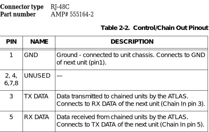
Control/Chain Out Port
The Control/Chain Out port (RJ-48C) connects to another ATLAS_800 Chain In connector. The Control/Chain Out port output provides the fol-lowing:
• EIA-232 output to chain control other ATLAS Base Units • 9600 or 2400 bps operation
• Automatic setup; no user input required
Connection
The Control Out/Chain Out connection follows, with the pinout shown in Table 2-2.
Connector type RJ-48C
Part number AMP# 555164-2
Table 2-1. Control/Chain In Pinout PIN NAME DESCRIPTION
1 GND Ground - connected to unit chassis
2 RTS Request to send - flow control
3 RXDATA Data received by the ATLAS_800 4 DTR Data terminal ready
5 TXDATA Data transmitted by the ATLAS_800 6 CD Carrier detect
7 UNUSED —
8 CTS Clear to send - flow control
Table 2-2. Control/Chain Out Pinout PIN NAME DESCRIPTION
1 GND Ground - connected to unit chassis. Connects to GND of next unit (pin1).
2, 4, 6,7,8
UNUSED —
3 TX DATA Data transmitted to chained units by the ATLAS. Connects to RX DATA of the next unit (Chain In pin 3).
Network Connection
Two eight-pin modular jacks labeled NTWK 1 and NTWK 2 provide the net-work connection. The two netnet-work interface (NI) ports comply with appli-cable ANSI and AT&T® standards. The NIs provide the following functions: • AMI or B8ZS coding
• Manual line build out • D4 or ESF framing
• Network performance monitoring and reporting • Test loopbacks with QRSS generation and checking • Extensive self-testing
Connection
The network connection follows, with the pinout shown in Table 2-3.
Connector type (USOC) RJ-48C
Part number AMP# 555164-2
10BaseT Ethernet Connection
The 10BaseT Ethernet port (RJ-48C) provides an Ethernet LAN connection which is used for TFTP, SNMP, and Telnet connection.
Connection
The network connection follows, with the pinout shown in Table 2-4.
Connector type (USOC) RJ-48C
Part number AMP# 555164-2
Table 2-3. Network Pinout
PIN NAME DESCRIPTION
1 R1 RXDATA-RING Receives data from the network.
2 T1 RXDATA-TIP Receives data from the network.
3, 6, 7, 8 UNUSED —
4 R TXDATA-RING Sends data toward the network.
MON
(Monitor) The MON bantam test jack provides a bridged access jack for non-intrusive monitoring of the T1 circuits receiving data. When connected to this jack, configure the test equipment for a bridged termination.
Option Slots
Figure 2-3 shows the option slot numbering designation, as viewed from the rear of the ATLAS_800. All slots are functionally identical except slots seven and eight, which can also accommodate an optional power supply for re-dundancy.
Figure 2-3. ATLAS_800 Slot Designation (Rear View)
INSTALL ANY OPTION MODULES
After installing the ATLAS_800 Base Unit and connecting the required ca-bles, you can install your choice of option modules. Instructions for install-ing option modules are given in the user manuals for the chosen modules.
Table 2-4. Ethernet 10BaseT Pinout PIN NAME DESCRIPTION
1 TX1 Transmit positive
2 TX2 Transmit negative
3 RX1 Receive positive
4, 5, 7, 8 UNUSED —
6 RX2 Receive negative
SLOT 1 SLOT 5
SLOT 2 SLOT 6
SLOT 3 SLOT 7
SLOT 4 SLOT 8 PO
W
E
R SUP
P
L
POWER-UP
As shipped, the ATLAS_800 is set to factory default conditions. After install-ing the ATLAS_800 Base Unit and any option modules, the ATLAS_800 is ready for power-up.
METHODS OF OPERATING THE ATLAS 800
You can access basic setup functions from the ATLAS_800 Front Panel. However, to access all of the ATLAS_800 functions, set up a Telnet session or use VT-100 terminal emulation and use the terminal menu. In addition, T-Watch PRO provides limited configuration control. The following sections provide an overview of these methods of operating the ATLAS_800. After deciding how you want to operate the ATLAS_800, you will be ready to configure the unit.
USING THE FRONT PANEL
With the ATLAS_800 powered-up, the Front Panel LCD window displays four menu items (see Figure 3-1). To select a menu item, either press the cor-responding number on the Front Panel keypad or press the Front Panel up and down arrows to scroll to the menu selection. For detailed information about the commands available through the Front Panel menus, see Front Panel Main Menu on page 4-6.
Figure 3-1. Front Panel LCD
Example 1
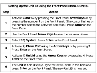
Using Front Panel Menu CONFIG to Set Up the Unit ID
Figure 3-2 shows the path you would follow to set up the Unit ID. The fol-lowing Step/Action table provides step-by-step instructions to do the same.
Figure 3-2. Example of Basic Front Panel Menu Navigation
USING THE TERMINAL MENU
The terminal menu provides a primary means of monitoring and configur-ing the ATLAS_800. The terminal menu interface uses the full capabilities of the VT-100 terminal to provide the quickest and most intuitive operation possible. To receive the full benefit of the terminal menu interface, you should use a fully VT-100 compatible client. The ADTRAN Utilities floppy disks contain both a VT-100 client and a customized Telnet program (install these on a PC). See ADTRAN Utilities on page 12-1 for details on the avail-able programs. You can access the terminal menu using a VT-100 terminal or a computer running VT-100 terminal-emulation software.
The two basic connection methods supported by the ATLAS_800 are a Tel-net session and a direct connection through the EIA-232 Chain In port. The following sections describe using both of these methods.
1) ETHERNET 1) BAUD RT 9600
S0) SYSTEM 2) FLOW CTL
2) CONFIG S1) 2) CHAIN PORT 3) TYPE
: 4) UNIT ID
S8) 5) INIT MODEM
Setting Up the Unit ID using the Front Panel Menu, CONFIG
Step Action
1
ActivateCONFIGby pressing the Front Panel arrow keysor by pressing the number2on the Front Panel. (The cursor flashes on the number next to the activated selection.) Press Enteron the Front Panel.
2 Use the Front Panel Arrow Keys to view the submenu items.
3 Select S0) System. PressEnteron the Front Panel.
4 Activate 2) Chain Portusing theArrow Keysor by pressing2.
PressEnter on the Front Panel.
5 Activate4) Unit Idusing theArrow Keys or by pressing4. Press Enteron the Front Panel.
6 TheUnit Idfield displays. Type the new Unit ID in this field and
Using Telnet
To connect to the ATLAS_800 via Telnet, define the IP address, set the sub-net mask, and, typically, set the default gateway IP address. The following Step/Action tables provide instructions for performing these tasks.
You must define the IP address before attempting to connect via Telnet.
Instructions for Defining the IP Address
Step Action
1 Obtain an IP address for the ATLAS_800 from your LAN
administrator.
2 From the Front Panel, select2) CONFIG, thenS0) SYSTEM, then 1) ETHERNET.
3 When the submenu displays, select1) IP ADDRESS.
4 Enter the IP address by entering each number followed by Enter
to move to the next field.
5 PressEnterafter keying in the entire IP address.
Instructions for Setting the Subnet Mask
Step Action
1 Obtain a subnet mask address from your LAN administrator.
2 From the Front Panel, select2) CONFIG, thenS0) SYSTEM, then 1) ETHERNET.
3 When the submenu displays, select 2) SUBNET MASK.
4 Enter the subnet mask by entering each number followed by Enterto move to the next field.
Starting a Telnet Session
When you begin the Telnet session, you will be prompted for a password. The default password is password (which is a Level 0 superuser password). You can change this password using the Access Passwords option, which is only accessible through the terminal menus. See Access Passwords on page 6-11 for details. The Telnet session will time out and display the Login prompt after a pre-defined time that is set in the Session Timeout option (see Session Timeout on page 6-7 for details).
For detailed information on the commands available during a Telnet ses-sion, refer to Chapters 5, 6, and 7 on working with the terminal menu.
Using VT-100 Terminal Emulation
An EIA-232 serial connection is available via the Chain In port on the rear panel of the ATLAS_800. The ATLAS_800 provides the Front Panel menus to a VT-100 type terminal. The following Step/Action table provides instruc-tions for setting up the ATLAS_800 for VT-100 terminal mode.
Instructions for Setting the Gateway IP Address
Step Action
1 From the Front Panel, select 2) CONFIG, thenS0) SYSTEM, then 1) ETHERNET.
2 When the submenu displays, select3) DEF GATEWAY.
3 Enter the default gateway by entering each number followed by Enterto move to the next field.
4 PressEnterafter keying in the entire address.
You will need a default gateway if the LAN contains multiple segments. Contact your LAN administrator for the appropriate address.
Use the Max Telnet Sessions option to define the number of Telnet sessions that can be active at one time (see Max Telnet Sessions on page 6-7 for details).
Microsoft Telnet version 1.0 does not implement full VT-100 emulation. However, many commercial Telnet clients for Microsoft Windows exist which fully implement VT-100. In addition, a freeware client which is recommended for optimum performance is delivered with the
After connecting a VT-100 terminal or a computer running VT-100 terminal-emulation software to this port, you may need to press Ctrl-R to refresh the screen display.
When you begin the VT-100 session, you will be prompted for a password. The default password is password (which is a Level 0 superuser password). You can change this password using the Access Passwords option, which is only accessible through the terminal menu. See Access Passwords on page 6-11 for details.
Using T-Watch PRO
T-Watch PRO is the ADTRAN Microsoft Windows management software program designed to control TSU units from a remote PC. It provides limit-ed control over the configuration of the ATLAS_800 using a graphic inter-face. Currently, you can choose ATLAS_800 from a list of products, and T-Watch PRO automatically initiates a Telnet session to which you can con-nect and manage the ATLAS_800 Base Unit. Currently, T-Watch PRO auto-matically receives SNMP traps from an ATLAS_800.
Instructions for Setting Up an ATLAS 800 for VT-100 Terminal Mode
Step Action
1 Set the baud rate on the VT-100 terminal to 9600 baud (8/N/1).
2
Use the Front Panel to set the ATLAS_800 baud rate to match the terminal baud rate. Select 2) CONFIG, S0) SYSTEM, 2)
CHAIN PORT, then 1) BAUD RATE.
3
Use the ADTRAN-provided VT-100 terminal adapter to connect the COM port of a VT-100 compatible terminal, or equivalent, to the eight-pin modular jack labeled CONTROL on the rear of the unit. This connection provides both local and remote
configuration.
4 Repeatedly press Enter on the Front Panel until the Login Menu
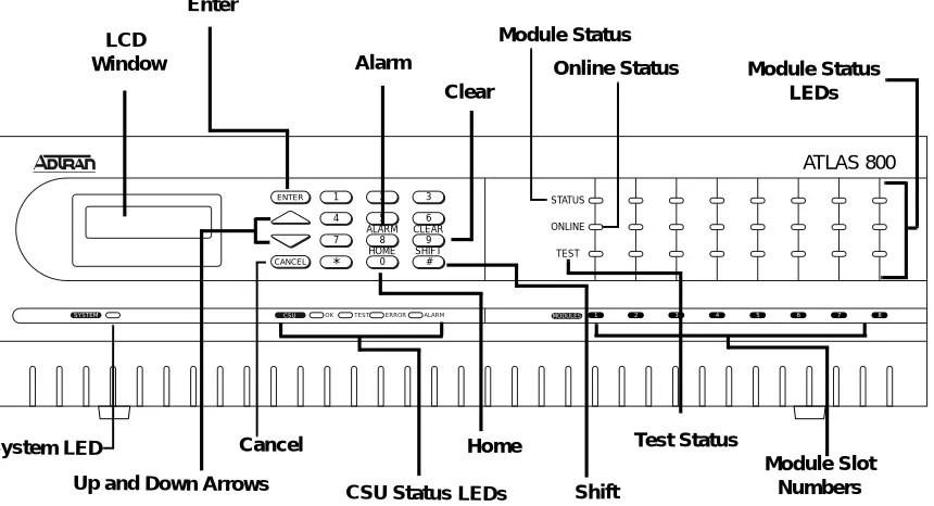
Use the Front Panel to select and set up the method of connectivity for con-trolling the ATLAS 800 Base Unit and to monitor the operation and status of the Base Unit. Figure 4-1 identifies the display panels and the operation keys located on the Front Panel.
Figure 4-1. ATLAS_800 Front Panel Layout
Table 4-1 on page 4-2 provides a brief description of the Front Panel features; Table 4-2 on page 4-3 provides detailed information about the LEDs; and Ta-ble 4-3 on page 4-4 provides information on operation keys.
ATLAS 800
1 2 3
*
HOME 0
SHIFT # 7
ALARM 8
CLEAR
STATUS
TEST ONLINE 9
4 5 6
ENTER
CANCEL
1
SYSTEM CSU OK TEST ERROR ALARM MODULES 2 3 4 5 6 7 8
LCD Window
Cancel
Up and Down Arrows CSU Status LEDs Enter
Home
Shift
Module Slot Numbers Clear
Module Status LEDs Module Status
Alarm
System LED
Online Status
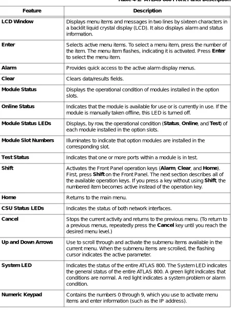
Table 4-1. ATLAS 800 Front Panel Description
Feature Description
LCD Window Displays menu items and messages in two lines by sixteen characters in a backlit liquid crystal display (LCD). It also displays alarm and status information.
Enter Selects active menu items. To select a menu item, press the number of the item. The menu item flashes, indicating it is activated. Press Enter to select the menu item.
Alarm Provides quick access to the active alarm display menus.
Clear Clears data/results fields.
Module Status Displays the operational condition of modules installed in the option slots.
Online Status Indicates that the module is available for use or is currently in use. If the module is manually taken offline, this LED is turned off.
Module Status LEDs Displays, by row, the operational condition (Status, Online, andTest) of
each module installed in the option slots.
Module Slot Numbers Illuminates to indicate that option modules are installed in the corresponding slot.
Test Status Indicates that one or more ports within a module is in test.
Shift Activates the Front Panel operation keys (Alarm, Clear, andHome).
First, pressShifton the Front Panel. The next section describes all of the available operation keys. If you press a key without usingShift, the numbered item becomes active instead of the operation key.
Home Returns to the main menu.
CSU Status LEDs Indicates the status of both network interfaces.
Cancel Stops the current activity and returns to the previous menu. (To return to a previous menus, repeatedly press the Cancel key until you reach the desired menu level.)
Up and Down Arrows Use to scroll through and activate the submenu items available in the current menu. When the submenu items are scrolled, the flashing cursor indicates the active parameter.
System LED Indicates the status of the entire ATLAS 800. The System LED indicates the general status of the entire ATLAS 800. A green light indicates that conditions are normal. A red light indicates a system problem or alarm condition.
Table 4-2. LED Descriptions For these LEDs... This color light... Indicates that...
System Green (solid) No diagnosed system faults were found. Green (fast blink) Flash download is in progress.
Yellow Fault was diagnosed, but the condition no longer exists. The condition will be recorded in the system log.
Red (solid) An error condition is present with either the power supply or temperature.
Red (fast blink) A fatal error occurred during flash download.
Off Power is not currently applied to the system.
CSU Status OK (green) Both network interfaces are operating normally with error-free operation. If either interface experiences alarms, the OK LED remains off.
Test (yellow) One of the interfaces is operating in a test mode. This includes a self-test, a test pattern, or a test loopback. When illuminated, this LED also indicates that normal data flow is not occurring in at least one of the module ports.
Error (flashing red) The Error LED indicates an error such as BPV (bipolar violation), OOF (out of frame), or CRC (cyclic redundancy check).
Alarm (red) An alarm condition has been detected. When the alarm condition is no longer valid, the OK LED illuminates. To view an alarm condition, select the active alarm menu item or select Alarm by pressing
Shift + 8. If the alarm conditions have been corrected,
you can view the alarm which caused the activation of the Alarm LED under the View History menu.
Module Status Green (solid) The module is OK.
Green (blinking) The module has been disabled by the user.
Red (solid) At least one port on the module has an alarm.
Red (blinking) The module is enabled, but is not responding to the system controller.
Off No module occupies the slot.
Module Online The module is available for use or is currently in use. If the module is manually taken offline, this LED is turned off.
OPERATION KEYS
Operation keys are ATLAS 800 Front Panel keys that perform alternate func-tions. To activate an operation key, simultaneously press the Front Panel
Shift key and the operation key that you want to activate, as shown in Table 4-3.
FRONT PANEL MENU STRUCTURE
The ATLAS_800 uses a multilevel menu structure containing both menu items and data fields. All menu operations and data display in the LCD win-dow. However, you only have access to limited configuration options through the Front Panel; to access all of the ATLAS_800 options, use the Ter-minal menu. See Navigating the TerTer-minal Menu on page 5-1.
The Front Panel opening menu (Main menu) is the access point to all other operations. Each Main menu item has several functions and submenus to identify and access specific parameters.
The Front Panel LCD of the Main menu contains the submenu options
STATUS, CONFIG, UTIL, and ALRM (see Figure 4-2).
Figure 4-2. Front Panel LCD Table 4-3. Operation Keys
To do this... Press these keys...
Access the active alarm display menus.
(This function can be activated while any other menu item is in use. When you exit the Alarm menu, the unit returns to the same menu that was active when you selected Alarm.)
Shift + Alarm
Clear data/result fields in various menus. Shift + Clear
Return to the Main menu from any menu location. Shift + Home
Selecting Front Panel Menus
To do this... Go to this menu... See also page...
Display the status of the ATLAS_800 STATUS 4-7 Display the card type in each slot STATUS 4-7 Perform limited configuration of the ATLAS_800 CONFIG 4-7 Monitor and modify miscellaneous settings UTIL 4-9
View a log of system events ALRM 4-11
Using the Front Panel Menus Menu Item/Activity... Comments...
Data Field Menu items followed by a colon (:) indicate a data field that you can edit, for example, changing the baud rate. See also Editing a Data Field on page 4-5.
Status Field Menu items followed by an equal sign (=) indicate the state of the item, for example, Online.
Select and Activate a Menu Item To select a menu item, place the cursor on the menu item
1. by pressing the number corresponding to the menu item or
2. by highlighting the menu item with the up or down arrows.
Exit any Menu Field Operation or Display
Press Cancel as many times as required to return to the desired menu level.
or
Press Home to return to the Main menu.
Editing a Data Field
Step Action
1 With the cursor positioned on the submenu item number, press Enter on the Front Panel.
The cursor moves to the data field (to the right of the submenu item name).
2 Use the Front Panel arrows to scroll and scan the available value settings.
(The value settings display one at a time.)
3
When the desired value displays, press Enter on the Front Panel to set the value.
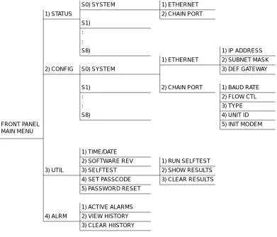
FRONT PANEL MAIN MENU
The Front Panel Main menu provides limited configuration and control of the ATLAS_800. Figure 4-3 shows the submenu options provided.
Figure 4-3. Front Panel Menu Tree 4 Select another data field to edit, or press Cancel to return to the submenu.
Pressing Cancel prior to pressing Enter voids any data changes. The original data value is restored and the cursor returns to the submenu field.
Editing a Data Field (Continued)
Step Action
S0) SYSTEM 1) ETHERNET
1) STATUS 2) CHAIN PORT
S1)
:
:
S8) 1) IP ADDRESS
1) ETHERNET 2) SUBNET MASK
2) CONFIG S0) SYSTEM 3) DEF GATEWAY
S1) 2) CHAIN PORT 1) BAUD RATE
: 2) FLOW CTL
: 3) TYPE
S8) 4) UNIT ID
FRONT PANEL MAIN MENU
5) INIT MODEM
1) TIME/DATE
2) SOFTWARE REV 1) RUN SELFTEST
3) UTIL 3) SELFTEST 2) SHOW RESULTS
4) SET PASSCODE 3) CLEAR RESULTS
5) PASSWORD RESET
1) ACTIVE ALARMS
4) ALRM 2) VIEW HISTORY
>
STATUS
The Status menu branch lets you view the status of the ATLAS_800 Base Unit and any installed modules.» S0 System
Displays status options that are available for the ATLAS_800 Base Unit. Choose from Ethernet (see Ethernet Status on page 4-7) or Chain Port (see Chain Port Status on page 4-7).»» Ethernet Status Shows the status of the 10BaseT Ethernet connection port. The following port status options display in the LCD window. An asterisk (*) indicates ac-tivity for the item.
»» Chain Port Status Indicates the status of the Chain Port. The following port status options dis-play in the LCD window. An asterisk (*) indicates activity for the item. (Read-only.)
» S1—S8
Displays the current status of installed modules. S1 corresponds to slot 1, S2to slot 2, and so on. When you select one of these options, an expanded de-scription of the card status displays. The status types include ON (Online),
OFF (Offline), NRSP (No Response), NRDY (Not Ready), and RST (Restart-ing).
>
CONFIG
The Config (Configuration) menu branch provides limited configuration control of the ATLAS_800.» S0 System
Displays configuration options that are available for the ATLAS_800 Base Unit. Choose from Ethernet Configuration (see Ethernet on page 4-8) orChain Port Configuration (see Chain Port on page 4-8).
To help you follow the terminal menu hierarchy, the following notations are used.
>
MENUS
» Submenus
»» Sub-submenus
TX Data is being transmitted from the 10BaseT port on the system con-troller.
RX Data is being received on the 10BaseT port.
LNK The current status of the 10BaseT link integrity test is indicated (LNK should always be on when the unit is connected to a function-al 10BaseT hub).
RTS Request to send.
CTS Clear To send.
DTR Data terminal ready.
»» Ethernet Allows you to create and change configuration settings for the 10BaseT Ethernet connection.
»» Chain Port The Chain Port configuration menu option modifies selected items in its menu branch.
IP Address Uniquely identifies the ATLAS_800 on a TCP/IP net-work. This address is composed of four decimal num-bers, each in the range of 0 to 255, separated by periods. This value is set to 0.0.0.0 by default. The IP address is used for the 10BaseT Ethernet interface. Obtain the cor-rect IP address from your LAN administrator. Enter the IP address by entering each number followed by Enter
to move to the next field.
You must define the IP address before attempting to use a Telnet program.
Subnet Mask Defines which part of a destination IP address is the Network number. This address is composed of four dec-imal numbers, each in the range of 0 to 255, separated by periods. This option is used along with the
ATLAS_800 IP address to determine which nodes must be reached through the default IP gateway. Enter the subnet mask address by entering each number followed by Enter to move to the next field.
Def Gateway Allows you to define or change the default gateway. You will need a default gateway if the LAN contains multi-ple segments. This address is composed of four decimal numbers, each in the range of 0 to 255, separated by periods. This value is set to 0.0.0.0 by default. Contact your LAN administrator for the appropriate address. Enter the default gateway address by entering each number followed by Enter to move to the next field.
Baud Rate Displays and changes the baud rate. The supported baud rates for the chain port include 2400 and 9600 bps. If Type is set to Dial, make sure this field matches the modem baud rate.
Flow Ctl Sets the flow control for the chain port. You can config-ure the chain port flow control for OFF or H/W (hard-ware).
Type Sets the Port Type to either Direct or Dial. Select Direct
» S1—S8
Displays the current configuration options of installed modules. S1 corre-sponds to slot 1, S2 to slot 2, and so on. When you select one of these options, you can enable or disable the selected module. The current status, ENA (En-abled) or DIS (Disabled), displays next to the module name. Set this field toDIS (Disable) prior to removing a module from the ATLAS_800 unit.
>
UTIL
The Utility menu allows miscellaneous settings to be displayed or modified.» Time/Date
Displays and/or edits the current time and date. The ATLAS_800 maintainsthe time and date during power off conditions.
After any numeric change, press Enter to record the entry and move to the next editing position. You can also move to a different field to edit by press-ing Enter at the editing position without making any change, or by using the
up and down arrowkeys. Press Cancel at any time to end the editing pro-cess.
» Software Rev
Displays the current software revision level loaded into the Base Unit con-troller. This information is required when requesting assistance from ADT-RAN Technical Support or when updates are needed. Press Cancel to exit this option.Unit ID Accesses the current Unit ID setting, which is the system identifier used for ADTRAN Data Link Layer Protocol (ADLP) configuration control (such as using T-Watch PRO).
Editing or changing the Unit ID requires the use of a passcode if a passcode is defined. See Set Passcode on page 4-11 for details on working with passcodes. Unit Identification numbers must be between 2 and 9999. The number 1 is reserved for the PC.
Press Enter to record the Unit ID number and establish its availability when operating by remote control. Press
Cancel at any time to end the editing process.
Init Modem Provides the option to send the modem initialization string (e.g., ATE0V1&D2S0=1) from the chain port to a modem connected to the chain port. Configure this string in the terminal menus. See Modem Initialization String on page 6-8 for details on how to change this field.
» Selftest
Executes a system self-test, and the LCD displays the Pass or Fail when the test is complete. Options include Run Selftest, Show Results, and Clear Re-sults.»» Run Selftest Initiates a self-test. When you select this option, the prompt Selftest, Are You Sure Y/N? displays. To initiate the self-test, select Y and press Enter. Se-lect N and press Enter to cancel the self-test.
If you select Y and proceed with the self-test, the LCD displays the message
Selftest in progress.... When the self-test is complete with no failures detected, the OK LED illuminates and the LCD momentarily displays
Self-Test Passed. If failures are detected, a list of failures displays in the LCD window.
The full self-test procedure consists of the following steps:
1. Board-level tests. An on-board processor executes a series of tests checking the circuitry on the board.
2. RAM tests; EPROM checksum.
3. TDM map tests.
4. On-board data path. Sending a known test pattern through an on- board loop.
5. Board-to-board interface test. Verifies the data path, clocks, and con-trol signals. A test pattern is sent from the concon-troller through a loop-back on all other boards and checked on the controller.
During a self-test, ATLAS_800 checks data integrity and verifies processor control to each port. Each port is looped back and a data pattern is sent and tested.
»» Show Results Displays the types of tests performed during a self-test, as well as the results of the tests. Each item in the list displays either Passed or Failed. A RAM test failure indicates a controller board problem. If a slot fails, the module in the slot may have a problem.The following items display:
The Selftest option disrupts data flow.
NVRAM Non-volatile RAM
DSP RAM Digital signal processor RAM
RTC RAM Real time clock RAM
TDM MAP TDM time slot mapping RAM
DRAM Dynamic program memory used for program execution
»» Clear Results Resets the self-test log that you access with the Show Results option. When you select this option, the message Self-Test Log Clearing displays. After the command is finished executing, the message Self-Test Log Cleared displays.
» Set Passcode
Provides security for Front Panel access. You can change or set the Front Panel passcode at any time or eliminate it altogether through the Set Pass-code option. By default, the Front Panel does not have a passcode.The passcode can only be entered by using numbers (any number except ze-ro). After entering the desired passcode, press Enter. The prompt Verify Passcode displays. Enter the passcode again and press Enter.
Set a null passcode by pressing 0 and then pressing Enter. When the Verify Password prompt displays, press 0 and Enter again. A null passcode grants unlimited access to Front Panel options.
» Password Reset
Creates a list of system passwords with the terminal menus (see Access Pass-words on page 6-11 for details). If you forget the password and are unable to log in to the terminal menus, use the Password Reset option. When you se-lect this option, two items display in the LCD window: CHALLENGE # andRESPONSE #.
Call ADTRAN technical support, and tell them the challenge number. They use this to generate a random response number. Enter this response number in the RESPONSE # field, and ATLAS_800 inserts a default password into the system password list. You can then use the new default password to log into the terminal menus.
>
ALRM MENU
From the ALRM (alarm) menu you can view a log of system events. To con-trol the types of events logged, a series of filters have been defined for each event source (System, T1/PRI, ISDN, Ethernet, etc.). Any event with a sever-ity greater than or equal to the threshold defined in the event logging filter list is logged to the system event log. Events that do not appear in the event log do not appear in the Front Panel alarm lists. Therefore, the event logging filters are applied to both the terminal and the Front Panel menu lists. See System Event Logging on page 6-10 for details on setting the thresholds for event logging.» Active Alarms
Displays a list of current alarms reported by the base controller. If no alarms are current, this menu item displays End of List. If there are current alarms, this display includes two lines of text. The top line is the alarm source. The bottom line is the alarm message.» View History
Displays a time and date-stamped list of the alarms that have occurred in the ATLAS_800. Some alarm types include -A to indicate the alarm is active and-I to indicate the alarm is inactive.
» Clear History
Clears the alarm history log.TERMINAL MENU WINDOW
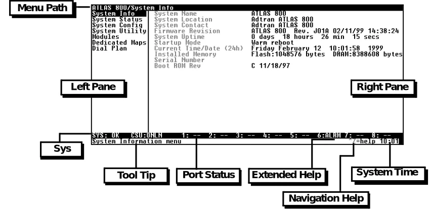
The ATLAS_800 uses a multilevel menu structure that contains both menu items and data fields. All menu items and data fields display in the terminal menu window, through which you have complete control of the ATLAS_800 (see Figure 5-1).
Figure 5-1. Top-level Terminal Menu Window
Menu Path
The first line of the terminal menu window (the menu path) shows the session’s current position (path) in the menu structure. For example, Figure 5-1 shows the top-level menu with the cursor on the System Info submenu; therefore, the menu path reads ATLAS 800/System Info.
Left Pane Right Pane
Menu Path
Sys
Tool Tip Port Status Extended Help
Navigation Help
Window Panes
When you first start a terminal menu session, the terminal menu window is divided into left and right panes. The left pane shows the list of available submenus, while the right pane shows the contents of the currently selected submenu.
Window Pane Navigation
Use the following chart to assist you in moving between and within the two window panes.
Right Window Pane Notation
The right window pane shows the contents of the currently selected menu. These contents can include both submenu items and data fields. Some sub-menus contain additional subsub-menus and some data fields contain additional data fields. The following chart explains the notation used to identify these additional items.
To move... Press one of these keys...
From left pane to right pane Tab Enter Left arrow Right arrow
From right pane to left pane Tab Escape Left arrow Right arrow
Within each pane Up arrow
Down arrow Left arrow Right arrow
This notation... Means that...
[+] More items are available when selected.
[DATA] More items are available when selected.
<+> An action is to be taken, such as activating a test.
Highlighted menu item You can enter data in this field.
Additional Terminal Menu Window Features
NAVIGATING USING THE KEYBOARD KEYS
You can use various keystrokes to move through the terminal menu, to man-age a terminal menu session, and to configure the system. Press Ctrl-Z to ac-tivate a pop-up screen listing the navigation keystrokes.
Moving through the Menus
Sys Describes the status of the ATLAS base unit (system).
Tool Tip Provides a brief description of the currently selected (highlighted) command.
Port Status Displays status information, such as OK, WARN, or ALRM, about ports 1—8.
Extended Help Displays information about selected commands (Ctrl-A).
Navigation Help Lists characters used for navigating the terminal menu (Ctrl-Z). See also Moving through the Menus on page 5-3
System Time Displays current time. See Current Time/Date (24h) on page 6-3 for details on editing the time.
To do this... Press this key...
Return to the home screen. H
Jump between two menu items.
Press J while the cursor is located on a menu item, and you jump back to the main screen.
Go to another menu item, press J, and you jump back to the screen that was displayed the first time you pressed J.
Press J anytime you want to jump between these items.
J
Select items. Arrows
Edit a selected menu item. Enter
Cancel an edit. Escape
Close pop-up help screens. Escape
Move between the left and right panes. Tab
Session Management Keystrokes
Configuration Keystrokes
Move to the top of a screen. A
Move to the bottom of a screen. Z
Ascend one menu level. Backspace
To do this... Press this...
Log out of a session. Ctrl-L
Invalidate the password entry and return to the login screen. Ctrl-S
Refresh the screen.
To save time, only the portion of the screen that has changed is refreshed. This option should only be necessary if the display picks up incorrect characters.
Ctrl-R
To do this... Press this key...
Restore factory default settings.
This setting restores the factory defaults based on the location of the cursor. If the cursor is on a module line (in the Modules menu), then only the selected module is updated to factory defaults.
F
Copy selected items to the clipboard.
The amount of information you can copy depends on the cursor location when you press C:
• If the cursor is over an editable field, only that item is copied. • If the cursor is over the index number of a list, then all of the items in
the row of the list are copied. For example, if the cursor is over the
Slot # field in the Modules screen, all of the information associated
with the slot is copied.
C
Paste the item stored in the clipboard, if the information is compatible.
You must confirm all pastes—except those to a single editable field.
P
Increment the value of certain types of fields by one when you paste information into those fields.
Getting Help
The bottom line of the terminal menu window contains context-sensitive help information. When the cursor is positioned over a set of configuration items, a help message displays (when available) providing a description of the item. When more detailed help is available for a particular item, ^A dis-plays at the bottom of the window. At this point, if you press Ctrl-A, a pop-up help screen displays with information about the item.
Press Ctrl-Z to activate a help screen that displays the available keystrokes you can use to navigate the terminal menu.
Decrement the value of certain types of fields by one when you paste information into those fi