T3SU 300 User Manual
1200217L1 DC Version Including AC Mains Power Supply
1200218L1 HSSI DTE Interface Card
1200219L1 V.35 DTE Interface Card
1200284L1 Quad DSX-1 Interface Card
1200217L2 AC Version
Trademark Information:
OpenView is a trademark of Hewlett-Packard Company. Spectrum is a registered trademark of Cabletron.
Netview is a registered trademark of IBM.
901 Explorer Boulevard P.O. Box 140000 Huntsville, AL 35814-4000
(256) 963-8000 © 2000 ADTRAN, Inc.
About this Manual
This manual is arranged so you can quickly and easily find the information you need. The following is an overview of the contents of this manual:
• Chapter 1, Introduction, familiarizes you with fiber networks and T3SU 300 high-lights and gives a brief explanation of the option cards that may be purchased for use with the T3SU 300.
• Chapter 2, Installation and Operation, describes the T3SU 300 connectors (pin assignments are given in Appendix A), provides installation instructions, and explains how to operate your T3SU 300 using the terminal interface.
• Chapter 3, Configuration, explains how to access the T3SU 300 Configuration menu, describes selections made in the Configuration menus, and provides a menu tree of Configuration options.
• Chapter 4, Status, describes each field of the Status menu.
• Chapter 5, Statistics, explains how to access statistical information for the T3SU 300 and describes each field.
• Chapter 6, Diagnostics, explains how to diagnose problems using loopback and BERT tests.
• Appendix A provides pinouts for the T3SU 300 connectors. • Appendix B contains product specifications.
Safety Instructions
When using your telephone equipment, please follow these basic safety precautions to reduce the risk of fire, electrical shock, or personal injury:
1. Do not use this product near water, such as a bath tub, wash bowl, kitchen sink, laundry tub, in a wet basement, or near a swimming pool.
2. Avoid using a telephone (other than a cordless-type) during an electrical storm. There is a remote risk of shock from lightning.
3. Do not use the telephone to report a gas leak in the vicinity of the leak.
4. Use only the power cord, power supply, and/or batteries indicated in the manual. Do not dispose of batteries in a fire. They may explode. Check with local codes for special disposal instructions.
Save These Important Safety Instructions
Notes provide additional useful information.
Cautions signify information that could prevent service interruption.
Limited Product Warranty
ADTRAN warrants that for five (5) years from the date of shipment to Customer, all products manufactured by ADTRAN will be free from defects in materials and work-manship. ADTRAN also warrants that products will conform to the applicable speci-fications and drawings for such products, as contained in the Product Manual or in ADTRAN's internal specifications and drawings for such products (which may or may not be reflected in the Product Manual). This warranty only applies if Customer gives ADTRAN written notice of defects during the warranty period. Upon such notice, ADTRAN will, at its option, either repair or replace the defective item. If ADT-RAN is unable, in a reasonable time, to repair or replace any equipment to a condition as warranted, Customer is entitled to a full refund of the purchase price upon return of the equipment to ADTRAN. This warranty applies only to the original purchaser and is not transferable without ADTRAN's express written permission. This warranty becomes null and void if Customer modifies or alters the equipment in any way, other than as specifically authorized by ADTRAN.
EXCEPT FOR THE LIMITED WARRANTY DESCRIBED ABOVE, THE FOREGOING CONSTITUTES THE SOLE AND EXCLUSIVE REMEDY OF THE CUSTOMER AND THE EXCLUSIVE LIABILITY OF ADTRAN AND IS IN LIEU OF ANY AND ALL OTHER WARRANTIES (EXPRESSED OR IMPLIED). ADTRAN SPECIFICALLY DIS-CLAIMS ALL OTHER WARRANTIES, INCLUDING (WITHOUT LIMITATION), ALL WARRANTIES OF MERCHANTABILITY AND FITNESS FOR A PARTICULAR PURPOSE. SOME STATES DO NOT ALLOW THE EXCLUSION OF IMPLIED WAR-RANTIES, SO THIS EXCLUSION MAY NOT APPLY TO CUSTOMER.
Additional Warranty Information
ADTRAN will replace or repair this product within five years from the date of ship-ment if the product does not meet its published specifications or if it fails while in ser-vice. For detailed warranty, repair, and return information refer to the ADTRAN Equipment Warranty and Repair and Return Policy Procedure.
Return Material Authorization (RMA) is required prior to returning equipment to ADTRAN.
Table of Contents
List of Figures ... xi
List of Tables ...xiii
Chapter 1. Introduction
Product Overview ... 1-1 T3 Overview ... 1-2 SNMP ... 1-2 TELNET ... 1-3 Interface Option Cards ... 1-3 HSSI Card... 1-4 V.35 Card... 1-4 Quad DSX-1 Card ... 1-4
Chapter 2. Installation and Operation
Table of Contents
DS3 Interface ... 2-7 Front Panel ... 2-7 Control Port... 2-7 Establishing Terminal Connection ... 2-7 Navigating Within the Menus ... 2-8 LED Descriptions ... 2-9 Remote Active ... 2-10 Network LEDs ... 2-10 DTE Port LEDs ... 2-10
Chapter 3. Configuration
Table of Contents
Password ... 3-20 Unit ID ... 3-20 Terminal Timeout ... 3-20 Date/Time... 3-20 Alarm Relay ... 3-21 Dialup Options ... 3-21 Primary and Secondary Phone Numbers ... 3-21 Initializing String ... 3-22 Dial String ... 3-22 Maximum Redial Attempts ... 3-22 Idle Timeout ... 3-22 Connection Timeout ... 3-22 Pause Between Calls ... 3-22 Dialout On Trap ... 3-22 Answer on Ring ... 3-23 Hangup ... 3-23 Last Modem Response ... 3-23 Utilities ... 3-23 Save Configuration ... 3-25
Chapter 4. Status
Network Port ... 4-1 DS3 Framing ... 4-1 Network State ... 4-2 Alarm State ... 4-2 Data Link State ... 4-3 Remote State ... 4-3 DTE Ports ... 4-4 Interface Type ... 4-4 Port Status ... 4-4 T1 Status ... 4-5 Bandwidth... 4-6 DTE Leads ... 4-6
Chapter 5. Statistics
Table of Contents
DS3 Payload Loopback ... 6-3 Line Loopback ... 6-3 BERT ... 6-4 Remote DS3 Loopback ... 6-4 Remote Loopback with BERT ... 6-4 DTE Ports 1-4 ... 6-4 HSSI and V.35 Diagnostic Options ... 6-5 Quad DSX-1 Diagnostic Options ... 6-8 BERT Configuration... 6-14 Pattern ... 6-14 Invert Pattern ... 6-15 BERT Information Fields ... 6-15 Insert Error ... 6-15 Clear Errors ... 6-15 Reset All Tests ... 6-15
Chapter 7. Applications
Single Port Full T3 Bandwidth ... 7-1 Point-to-Point Multiport Application ... 7-2 Fractional T3 Carrier Application ... 7-4 Remote SNMP Management Application ... 7-6 Voice Application ... 7-7
Appendix A. Pinouts... A-1
Appendix B. Specifications Summary ... B-1
Appendix C. Acronyms/Abbreviations... C-1
Appendix D. Glossary ... D-1
List of Figures
List of Figures
List of Tables
Chapter 1
Introduction
PRODUCT OVERVIEW
The T3SU 300 is a multiport DSU/CSU (data service unit/channel service unit) that provides access to T3 services. The unit provides a cost-effective, versatile approach for migrating T1 services to T3. The TDM (time division multiplexer) multiport design allows you to share the cost of a T3 line between multiple applications. This unit maximizes the use of T3 services, providing up to four data ports capable of transmitting and receiving high-capacity, real time data.
A HSSI (high speed serial interface) port is built in along with three slots which accept additional HSSI, V.35, or Quad DSX-1 interface cards. The HSSI interfaces support rates between 75 kbps and 44.2 Mbps in 75 kbps increments. The high speed V.35 interface option supports rates up to 10 Mbps in increments of 75 kbps. The Quad DSX-1 interface card provides four DSX-1 lines. Each DSX-1 port supports rates up to 1.544 Mbps.
Chapter 1. Introduction
Complete configuration, diagnostics, and performance monitoring are available through SNMP, TELNET, or a VT-100 terminal interface. This connection can be made via ethernet, a local EIA-232 link, or through the built-in V.34 modem. Advanced dial-out on trap capabilities through the built-in modem allow the T3SU 300 to contact remote hosts and alert them to DSX-3 network conditions (without dedicated management connections). The T3SU 300 is designed for either desktop use or installation in a 19-inch rack. The major features or the T3SU 300 are as follows:
• Full feature multiport T3 DSU/CSU
• Maximum of four user data ports: one integrated HSSI port and three additional slots for optional HSSI, high speed V.35, or Quad DSX-1 cards
• Automatic or manual remote configuration
• Embedded SNMP and TELNET management through 10BaseT ethernet or SLIP/PPP
• Detailed performance monitoring for local and remote units • Simplified configuration through detailed VT-100 terminal
menu structure
• Integrated V.34 modem for dial-up and dial-out access • Standard 5-year warranty
T3 OVERVIEW
T3 provides the same bandwidth as 28 T1s and is used to
interconnect high-speed bridges, routers, front-end processors, and data terminal equipment (DTE). T3 service plays a major role in Internet backbones and public organizations needing broad bandwidth for WAN (wide area network) connectivity.
SNMP
Chapter 1. Introduction
(LAN) port. The T3SU 300 supports the MIB-II standard, RFC 1213, and the ADTRAN Enterprise Specific MIB.
The term SNMP broadly refers to the message protocols used to exchange information between the network management system (NMS) and the managed devices, as well as to the structure of device management databases. SNMP has three basic components:
Network Manager
Control programs that collect, control, and present data pertinent to the operation of the network devices. These programs reside on a network management station.
Agent
Control program that resides in every network device. This program responds to queries and commands from the network manager, returns requested information or invokes configuration changes initiated by the manager, and sends unsolicited traps to the manager.
MIB
Industry standard presentation of all status and configuration parameters supported by a network device.
TELNET
TELNET provides a password-protected, remote login facility to the T3SU 300 that allows a remote user to control the T3SU 300 through the terminal menus. Only one TELNET session may be active at a time.
INTERFACE OPTION CARDS
Optional interface cards may be purchased to equip the T3SU 300 with up to three additional ports. HSSI, V.35, and Quad DSX-1
Chapter 1. Introduction
HSSI Card
The optional HSSI card plugs into one of the three card slots on the rear of the T3SU 300. With optional HSSI cards installed, the total 44.2 Mbps bandwidth of the T3 can be divided among the total number of ports to provide multiple data channels over the T3. The total bandwidth of the T3 can be divided among the available ports in any fashion, as long as the divisions are on 75 kbps boundaries. The HSSI card can be hot inserted or swapped. When it is inserted in a slot on the rear panel and its faceplate is secured to the rear panel of the T3SU 300 with the integral thumb screws, a PCMCIA type connector on the card mates with a compatible connector on the main board of the T3SU 300. A standard 50-pin HSSI connector is then available for DTE connections. See the section DTE Port Interface Card Slots on page 2-6 for more information on installing option cards.
V.35 Card
The optional V.35 card plugs into the card slots on the rear of the T3SU 300 to provide a V.35-type DTE interface. Operation of the V.35 card is similar to that of the HSSI card except that the maximum bandwidth of the V.35 card is limited to 10 Mbps. Like the HSSI card, the V.35 card can be hot inserted or swapped, and it installs just as the HSSI card does. Instead of the standard HSSI connector, this card contains a standard 34-pin V.35 connector for DTE connections. See the section DTE Port Interface Card Slots on page 2-6 for more information on installing option cards.
Quad DSX-1 Card
Chapter 1. Introduction
network interface. Up to three cards may be installed into any of the T3SU 300 DTE port card slots.
Chapter 2
Installation and Operation
RECEIVING INSPECTION
Carefully inspect the T3SU 300 for any damage that may have occurred in shipment. If damage is suspected, file a claim immediately with the carrier and contact ADTRAN Technical Support (see the back cover of this manual). Keep the original shipping container to use for future shipment or verification of damage during shipment.
ADTRAN Shipments Include
The following items are included in ADTRAN shipments of the T3SU 300:
• T3SU 300 unit • User manual
• An 8-position modular to 8-position modular cable (part number: 3127004)
• An 8-position modular to DB-25 female connector (part number: 3196ADPT005)
• A 4-position modular to 4-position modular cable (part number: 3127014)
Chapter 2. Installation and Operation
• Rubber feet for stand-alone use
Customer Provides
The customer provides an interface cable for each port used. Each cable should be either HSSI, V.35, or an 8-pin modular cable, depending on the interface type.
Power Up
The AC version of the T3SU 300 is provided with a captive eight-foot power cord, terminated by a three-prong plug which connects to a grounded 115 VAC power receptacle.
A three-position terminal block which accommodates 12 to 26 AWG wire is located on the rear panel of the T3SU 300 DC version. The positive (+) and negative (-) terminals connect to a 24 to 48 VDC, 0.4A power source. Figure 2-1 provides an illustration of the terminal block power connector, along with definitions for the three connector symbols.
The ADTRAN T3SU 300 MIB is available in the support section of the ADTRAN web page at www.adtran.com.
Power to the AC version of the T3SU 300 must be provided from a grounded 115 VAC, 60 Hz receptacle.
Chapter 2. Installation and Operation
Figure 2-1. DC Power Connector
The following UL requirements must be met during installation of the DC version of the T3SU 300:
1. The unit must be connected to a reliably grounded -24 or -48 VDC source which is electrically isolated from the AC source. 2. The branch circuit overcurrent protection should be a fuse or
circuit breaker rated 48 V, 15 A.
3. The unit should be installed in accordance with the requirements of NEC NFPA 70.
4. A readily accessible disconnect device that is suitably approved and rated should be incorporated in the fixed wiring.
INSTALLING THE UNIT
The T3SU 300 can be used as a desktop stand-alone device or mounted into a standard 19-inch equipment rack. See the section Establishing Terminal Connection on page 2-7 for information on terminal configuration.
Rackmount Installation
Follow these steps to mount your unit into a rack:
Symbol Definition
Frame ground.
+ Positive side of DC power source (usually ground).
Chapter 2. Installation and Operation
T3SU 300 enclosure at one of the three available positions.
2. After the flanges have been installed, position the T3SU 300 at the correct location within the rack and secure the mounting flanges to the mounting rails of the rack.
3. Make all network, DTE, and power connections to the rear of the unit. See the section Power Up on page 2-2 for more information on making the DC power connection.
4. Using the 8-position modular to DB-25 female connector and the 8-position modular to 8-position modular cable, connect a VT-100 terminal device to the CONTROL interface jack on the front panel of the unit.
Desktop Installation
Follow these steps when using your T3SU 300 as a desktop unit: 1. Affix the four adhesive-backed rubber feet to the bottom of the
unit, one in each of the four corners. The feet should be placed approximately one inch from the front or back and one inch from the sides of the unit
2. Make all network, DTE, and power connections to the rear of the unit. See the section Power Up on page 2-2 for more information on making the DC power connection.
3. Using the 8-position modular to DB-25 female connector and the 8-position modular to 8-position modular cable, connect a VT-100 terminal device to the CONTROL interface jack on the front panel of the unit.
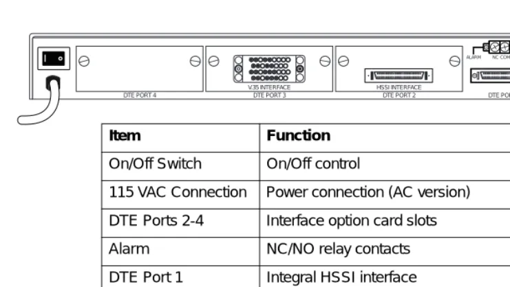
REAR PANEL
The T3SU 300 is equipped with three option card slots, a built-in HSSI interface, an alarm output terminal block, an auxiliary (AUX) port, a LAN port, and a DS3 interface. Pin assignments for
Chapter 2. Installation and Operation
connectors are given in the appendix Pinouts on page A-1. The T3SU 300 rear panel is shown in Figure 2-2.
Figure 2-2. T3SU 300 Rear View (AC Version)
DTE Port Interface Card Slots
The T3SU 300 rear panel has three card slots for the installation of optional interface cards. To insert cards, perform the following procedure:
1. Remove blank slot cover from the rear of the T3SU 300. 2. Slide the card into the corresponding rear slot until the card
panel is flush with the T3SU 300 chassis.
3. Push in thumbscrews and turn clockwise to secure the card and ensure proper connection to the main board of the T3SU 300.
DTE PORT 4
DJNTXBBFFLL BFLRVZDDJJNN
CHMSWAAEEKK AEKPUYCCHHMM V.35 INTERFACE
DTE PORT 3
HSSI INTERFACE
DTE PORT 2 DTE PORT 1
NC COM NO AUX LAN ALARM
RX IN TX OUT
DS3 INTERFACE
Item Function
On/Off Switch On/Off control
115 VAC Connection Power connection (AC version)
DTE Ports 2-4 Interface option card slots
Alarm NC/NO relay contacts
DTE Port 1 Integral HSSI interface
Aux Telephone line connection for internal V.34 modem
LAN 10BaseT LAN connection
Chapter 2. Installation and Operation
Alarm Connector
The alarm connector is a three-position, screw-type terminal block that is connected to the three contacts of a Form C-type relay on the main board of the T3SU 300. This relay is activated any time the T3SU 300 detects an alarm condition on the T3 network interface. The alarm function can be disabled through the ALARM RELAY selection of the CONFIGURATION menu.
DTE Port 1 (HSSI Interface)
DTE port 1 is a built-in HSSI port that resides on the main board of the T3SU 300. The bandwidth of this port is configurable from 75 kbps to 44.2 Mbps in either 75 kbps or 3.16 Mbps increments. When a single application requires the full 44.2 Mbps of
bandwidth, the T3SU 300 does not have to be equipped with additional port cards.
Auxiliary Port
The auxiliary (AUX) port is an 8-pin modular jack located on the rear panel of the T3SU 300. The AUX port provides a telephone line (POTS) connection for the internal V.34 modem.
The T3SU 300 can be configured as a in host and also as a dial-out-on-TRAP device (meaning that the unit dials out to a specified host to report error conditions). Configure the modem parameters in the DIALUP OPTIONS menu under the SYSTEM MANAGEMENT portion of the CONFIGURATION menu (CONFIGURATION-> SYSTEM MANAGEMENT -> DIALUP OPTIONS).
LAN Port
Chapter 2. Installation and Operation
DS3 Interface
The DS3 network interface is a full-duplex circuit provided by two BNC coaxial cable connections. The receive data from the network is connected to the RXIN connector, while the transmit data from the T3SU 300 is connected to the TX OUT connector.
FRONT PANEL
The T3SU 300 faceplate is shown in Figure 2-3. Descriptions of each part of the front panel follow.
Figure 2-3. T3SU 300 Front Panel
Control Port
The T3SU 300 has an 8-pin modular jack labeled CONTROL. The control port provides connection to a VT-100 EIA-232 compatible interface.
Establishing Terminal Connection
To control the T3SU 300 using a VT-100 terminal, follow this procedure:
1. Configure the VT-100 terminal for 9600 baud, 8-bit characters, no parity, and one stop bit (9600, 8N1).
2. Using the ADTRAN-provided terminal interface cable adapter, connect the DTE port of a terminal to the 8-pin modular jack labeled CONTROL on the front panel of the T3SU 300.
Chapter 2. Installation and Operation
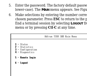
5. Enter the password. The factory default password is adtran (all lower-case). The MAIN menu appears. See Figure 2-4.
6. Make selections by entering the number corresponding to the chosen parameter. Press ESC to return to the previous screen. End a terminal session by selecting LOGOUT from the MAIN menu or by pressing Ctl-C at any time.
Figure 2-4. Terminal Main Menu
Navigating Within the Menus
Navigate within the T3SU 300 terminal menus using the following procedures:
If you want to... Press...
select an item the number corresponding to your choice, and then press the Enter key.
scroll between screens within the same selection
the up and down arrow keys. Additional screens are available when UP or DOWN is displayed in the right-hand side of the menu.
scroll left and right within the same screen
the left and right arrow keys. Additional screens are available when < or > is displayed in the top portion of the menu.
return to the previous menu
Chapter 2. Installation and Operation
Status
This selection provides status information on the network and DTE ports. See the chapter Status on page 4-1 for more information.
Statistics
This selection provides statistical information for the network and DTE ports. See the chapter Statistics on page 5-1 for more
information.
Configuration
The CONFIGURATION menu is used to set network, DTE, and system management parameters. See the chapter Configuration on page 3-1 for more detailed information.
Diagnostics
The DIAGNOSTICS menu is used to perform loopback and BERT tests. See the chapter Diagnostics on page 6-1 for more detailed information.
Remote Login
The REMOTE LOGIN selection allows you to configure the remote T3SU 300. The remote unit’s password is required at login. The
DATA LINK option (in the DS3 NETWORK CONFIGURATIONmenu) must be enabled in order to perform remote configuration.
Logout
The LOGOUT selection ends the terminal session and logs out of the system. Password entry is required before a new session can begin.
LED Descriptions
The T3SU 300 has LED status indicators for remote access, the network port, and for each individual DTE port. These LEDs are identified as follows:
end the terminal session
Ctl-C.
Chapter 2. Installation and Operation
Remote Active
This LED is solid when a remote configuration session is taking place through a TELNET session or from the remote end T3SU 300. It flashes when the unit is being accessed locally through the front panel CONTROL port.
Network LEDs
In Service
This LED is active when a valid signal is being received on the DS3 interface.
In Test
This LED is active when the network interface has been put in loopback by the service provider.
Alarm
This LED is active when the DS3 receive signal contains framing errors, the yellow alarm is received from the far end unit, or other alarm messages are received from the network.
LOS
This LED is active when no receive signal from the network is detected on the Rx (in) circuit.
DTE Port LEDs
Status
This LED indicates the following conditions:
LED Condition
Off No option card is installed.
Flashing green Interface is available but not configured.
On green Interface is available and configured.
On red DTE fault condition (for HSSI interface, no clock from DTE).
Chapter 2. Installation and Operation
In Test
This LED is active when the DTE interface is in a loopback condition or is performing a BERT test.
TD
This LED is active when the T3SU 300 DTE port is transmitting data.
RD
Chapter 3
Configuration
The T3SU 300 can be configured locally and remotely. Local configuration is accomplished through a 10BaseT ethernet connection, a SLIP/PPP port, or a VT-100 terminal. Remote configuration can take place through the T3 datalink using a local T3SU 300.
The CONFIGURATION menu consists of the following submenus relating to specific interfaces or functions:
DS3 NETWORK
DTE PORTS
SYSTEM MANAGEMENT UTILITIES
SAVE CONFIGURATION
Chapter 3. Configuration
Figure 3-1. Configuration Main Menu
DS3 NETWORK
Select 1 DS3 NETWORK to access the network configuration parameters. Configure the T3SU 300 network settings to match the T3 signal received from the service provider. During remote configuration, this menu is read-only. The DS3 NETWORK
Chapter 3. Configuration
Figure 3-2. DS3 Network Configuration Menu
DS3 Framing
Set the framing format to match the format of the receive signal at the network interface. C-BITPARITY and M13 framing formats are supported. Select AUTO to allow the interface to detect the framing type automatically.
Line Length
Set the line length to reflect the physical length of the DS3 network line. Set to LONG if the cabling distance exceeds 50 feet; set to SHORT if the distance is less than 50 feet.
DS3 Timing
Set the timing to LOOP if the T3SU 300 is to derive timing from the network; set to LOCAL if the unit is to be the master timing source for the circuit. In most cases, the unit should be configured for
Chapter 3. Configuration
DS3 Scrambler
Enable this option to scramble the DS3 payload data. This prevents certain transport equipment from falsely reporting alarms.
Multiplexing Mode
The Multiplexing Mode menu allows you to select the DTE port bandwidth increment size. The increment size of Nx75 kbps allows the user to divide 588 blocks among the four ports. The increment size of Nx3.16 Mbps has 14 blocks available, and ports 2, 3, and 4 are disabled. Only port 1, the built-in HSSI port, is available in this mode. The Nx3.16 Mbps mode provides compatibility with Juniper and Cisco routers at below full-bandwidth rates. When the user switches the multiplexing mode, the system will reboot causing service interruption. Loading default settings does not reset this option.
Data Link
Set to ENABLE to allow for remote configuration. When enabled, the T3SU 300 provides a channel between the local and the remote DSU for point-to-point remote configuration.
Remote Auto-Configuration
This feature allows one T3SU 300 (set to MASTER) to automatically relay its DTE port bandwidth configuration to a second unit (set to
SLAVE). If desired, the feature can be disabled by either unit.
DTE PORTS
The DTE PORTSmenu allows you to select a port to configure. If
REMOTE AUTO CONFIGURATION is set to MASTER (CONFIGURATION ->
Chapter 3. Configuration
Configuration selections for the individual ports are described in the following section. A more in-depth description of TIMED PROFILES is on page 3-12.
Figure 3-3. DTE Ports Menu
Port Selections 1-4
Select DTE PORT 1, 2, 3, or 4 to access the port configuration parameters. Configure each DTE port to be compatible with the DTE equipment attached to it. PORT CONFIGURATIONmenu examples are shown in Figure 3-4 and Figure 3-5. Descriptions of the individual fields follow the illustration. The descriptions are listed in tables based on the DTE port interface type (HSSI, V.35, or Quad DSX-1).
• Table 3-1 on page 3-7 lists the menu fields available for HSSI and V.35 interfaces.
• Table 3-2 on page 3-8 lists the menu fields available for V.35 interfaces (in addition to those listed in Table 3-1).
Chapter 3. Configuration
Chapter 3. Configuration
Configuration Selections for HSSI and V.35 Interfaces
The configuration selections listed in Table 3-1 are available for HSSI and V.35 interfaces. Additional selections listed in Table 3-2 on page 3-8 apply only to V.35 interfaces.
Table 3-1. HSSI and V.35 Configuration Selections
Selection Description
INTERFACE TYPE This read-only status field shows the interface type of the selected port (HSSI or V.35).
PORT STATUS This read-only status field displays one of the following messages to show the port status of the selected port:
INACTIVE: The port is installed, but idle. Activate a port through the PORT STATE field of this menu.
ACTIVE: The port has been configured and is passing data.
WAITING: The port has been configured and is waiting for the DTE to issue the appropriate handshaking signals. For the HSSI interface, the terminal equipment available (TA) signal must be asserted by the DTE. For V.35, DTR is required if the TR field in this menu is set to IDLE WHEN OFF; otherwise, DTR is ignored.
ERROR: An error condition such as loss of transmit clock has occurred.
NOT INSTALLED:An interface card is not installed in the selected port. If a port is not installed, the remainder of the PORT CONFIGURATIONmenu does not appear.
PORT STATE If a port is installed but not currently in use, set to DISABLED. Set to
ENABLED to activate an installed port.
NX75K BLOCKS This field determines the amount of bandwidth allocated to the selected port. For an HSSI interface, the selections are from 1-588 (yielding a bandwidth of 75.2 kbps to 44.2 Mbps). For a V.35 interface, the selections are from 1-140 (yielding a bandwidth of 75.2 kbps to 10.5 Mbps). Changes to this field do not take effect until APPLY SETTINGS is selected.
Chapter 3. Configuration
APPLY SETTINGS Select this field after making all configuration changes for the selected port. The changes are then applied to the unit immediately. Applying the settings briefly affects all ports of the T3SU 300. You may cancel changes made to the current PORT CONFIGURATION menu by pressing the ESC key.
Note: Additional configuration selections are available for V.35 interfaces. These selections are listed in Table 3-2.
Table 3-2. Additional V.35 Interface Port Configuration Selections
Selection Description
CS Selects the control mode for the clear to send (CS) lead.
FORCED ON: The CS lead remains on and request to send (RS) is ignored as long as the unit is synchronized and able to pass data.
FOLLOW RS: The CS state matches the RS state.
TR Selects the T3SU 300’s response to the data terminal ready (TR) lead.
IGNORED:The T3SU 300 ignores the state of the TR lead.
IDLE WHEN OFF: The T3SU 300 suspends traffic on the selected port if the TR lead is off.
SR Selects the control mode for the data set ready (SR) lead.
FORCED ON: The SR control lead remains on regardless of the state of the network.
OFF WHEN OOS/OOF: The SR control lead remains on unless the T3SU 300 receives an out of service/out of frame (OOS/OOF) condition from the network.
OFF WHEN TEST: The SR lead remains on except when the T3SU 300 is executing a test.
OFF WHEN OOS/OOF OR TEST: The SR lead remains on except when the unit receives an OOS/OOF condition from the network or when the unit is executing a test.
Table 3-1. HSSI and V.35 Configuration Selections
Chapter 3. Configuration
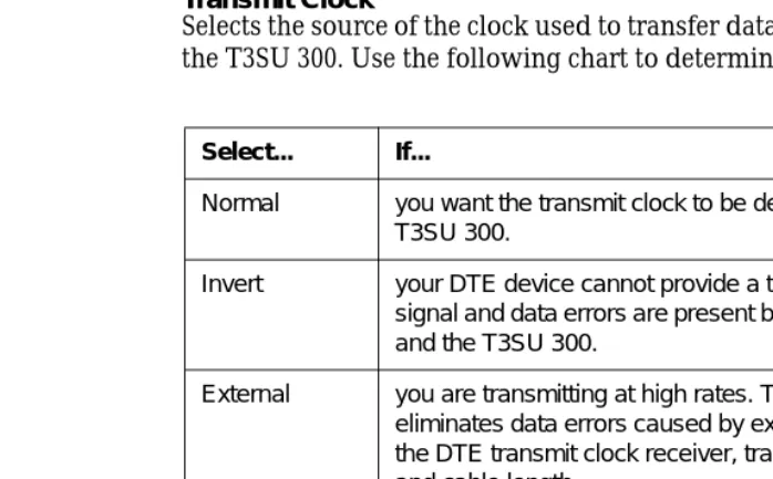
Transmit Clock
Selects the source of the clock used to transfer data from the DTE to the T3SU 300. Use the following chart to determine your selection:
Configuration Selections for DSX-1 Interfaces
The configuration selections listed in Table 3-3 are available for Quad DSX-1 interfaces. Separate selections can be made for each of the four DSX-1 ports of the card. This menu is shown in Figure 3-5.
CD Selects the control mode for the carrier detect (CD) lead.
FORCED ON: The CD lead remains active at all times.
OFF WHEN OOS/OOF: The CD control lead remains on unless the T3SU 300 receives an OOS/OOF condition from the network.
TRANSMIT CLOCK See the following section for a description of this item.
Table 3-2. Additional V.35 Interface Port Configuration Selections
Selection Description
Select... If...
Normal you want the transmit clock to be derived from the T3SU 300.
Invert your DTE device cannot provide a transmit clock signal and data errors are present between your DTE and the T3SU 300.
External you are transmitting at high rates. This selection eliminates data errors caused by excessive delays in the DTE transmit clock receiver, transmit data driver, and cable length.
Chapter 3. Configuration
Figure 3-5. Port Configuration Menu (Quad DSX-1 Interface Card)
The Quad DSX-1 does not perform ESF to SF (D4) conversion through the network. Therefore, both ends of the circuit must be configured for the same framing type.
Table 3-3. DSX-1 Interface Port Configuration Selections
Selection Description
INTERFACE TYPE This read-only status field displays QUAD DSX-1, indicating that a Quad DSX-1 interface card is installed in the DTE Port card slot.
PORT STATUS This read-only status field displays INACTIVE, ACTIVE, WAITING, ERROR, OR NOT INSTALLED, indicating the current status of the DSX-1 interface.
UNALLOCATED 75K BLOCKS
Displays the amount of bandwidth (in 75k increments) not already allocated to any of the T3SU 300 DTE ports.
Chapter 3. Configuration
FRAMING Select the framing format for each individual DSX-1 interface. The default setting is ESF. Select ESF if your DTE device is configured for Extended Superframe framing. Select D4 if your DTE device is configured for D4 framing. Select AUTO to allow the interface to detect the framing type (ESF or D4) automatically. When in AUTO mode, the selected interface toggles between ESF and D4 approximately every ten seconds until it detects valid framing.
Note: D4 is equivalent to superframe format (SF).
LINE CODING Set the line code for each individual DSX-1 interface to match the connected DTE device. Three choices are available: B8ZS, AMI, and
AMI W/STUFFING (AMI coding with bit stuffing).
LINE LENGTH Set the line length for each DSX-1 interface according to the distance from the T3SU 300 to your DTE device. Set to 7.5 dB if the attached DTE device only supports DS-1 levels.
DSX-1 TIMING SOURCE
For each Quad DSX-1 card pair (the near- and far-end Quad DSX-1 cards), there must be only one source of timing. The available timing sources are described below:
DS3: The timing for both the near- and far-end Quad DSX-1 cards is derived from the DS3 interface. All DTE devices connected to the DSX-1 interfaces must be slave timed since both cards source the timing reference derived from the DS3. Both the near- and far-end units must be set to DS3.
REMOTE: The timing source for the Quad DSX-1 card is derived from the far-end Quad DSX-1 card. Use this mode if the far-end card has a
DSX-1 TIMING SOURCE configuration of DSX-1 #1, DSX-1 #2, DSX-1 #3, or DSX-1 #4.
DSX-1 #X(x is 1,2,3, or 4): The timing source for the Quad DSX-1 pair is derived from one of the four DSX-1 interfaces. When configured in this manner, one of the DSX-1 interfaces is slaved to the DSX-1 interface from your DTE. The remaining three DSX-1 interfaces, if enabled, source the timing as derived from the slaved port. The far-end DSX-1 interface must be configured for REMOTE.
Note: If more than one Quad DSX-1 card is installed, each card can have a different timing source configuration.
APPLY SETTINGS Select this field after making all configuration changes for the selected
Table 3-3. DSX-1 Interface Port Configuration Selections (Continued)
Chapter 3. Configuration
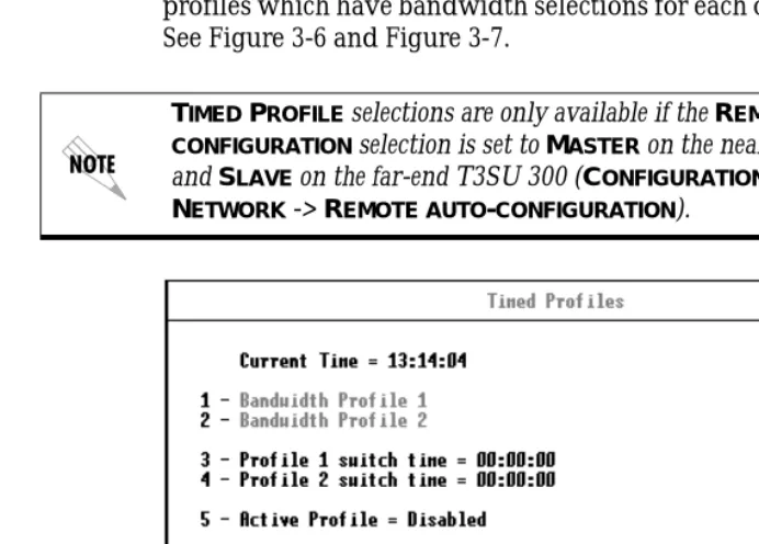
Timed Profiles
Using this option, you can allocate bandwidth based on the time of day. For example, you can assign more bandwidth to the corporate LAN during business hours and more bandwidth to a backup machine in the evenings. The T3SU 300 can store two separate user profiles which have bandwidth selections for each of the four ports. See Figure 3-6 and Figure 3-7.
Figure 3-6. Timed Profiles Screen
Bandwidth Profiles 1 and 2
The PROFILE CONFIGURATION screens allow you to change the PORT STATE and NX75K BLOCKS options for HSSI and V.35 ports. See page 3-7 for descriptions of these options. This screen also allows you to enable or disable each individual DSX-1 interface of a Quad DSX-1 card at the time of day specified in the given profile. Settings for all port types are assigned to the selected profile (1 or 2) and will apply whenever that profile is active. See Figure 3-7.
Chapter 3. Configuration
Profile Switch Time (1 and 2)
Enter the time that you want the profile to become active. Enter the time in military time (i.e., 00:00:00 = 12 AM). The profile remains active until one of the following occurs: (1) the other profile’s activation time comes about, or (2) the profile is disabled manually through the ACTIVE PROFILE selection.
Active Profile
Use this field to either manually force a profile to become active (regardless of the time of day) or disable the profiles completely.
Figure 3-7. Example of a Profile Configuration Menu
SYSTEM MANAGEMENT
The SYSTEM MANAGEMENT menu allows you to configure the T3SU 300 for management through SNMP, TELNET, or a VT-100
interface. Embedded SNMP and TELNET are available through either a SLIP/PPP or a 10BaseT ethernet port. The SYSTEM
Chapter 3. Configuration
Figure 3-8. System Management Configuration Menu (1 of 2)
Local IP Address
Enter the T3SU 300 IP address. This IP address applies to the ethernet or auxiliary port (when configured for PPP or SLIP). This address is available from the network administrator.
Subnet Mask
Enter the subnet mask of the T3SU 300. This address is available from the network administrator.
Gateway IP Address
Chapter 3. Configuration
Remote IP Address
Enter the remote T3SU 300’s IP address to provide network management access through the local T3SU 300. See the section Remote SNMP Management Application on page 7-7 for more information.
IP Security
Enable or disable the IP Security option. If enabled, the unit accepts management commands and TELNET sessions from the IP
addresses entered into the IP HOSTS fields.
IP Hosts
Enter up to 16 IP addresses of management stations from which the unit should accept management commands. These addresses are only applicable if IP SECURITY is enabled.
Management Port
Assign the management port to be either LAN, FDL (facility datalink), or the AUXPORT.
Modem Mode
Select the AUX port function for your application. The AUX port, located on the rear panel of the T3SU 300, provides a telephone line (POTS) for connecting to the internal V.34 modem. The modem interface can be configured for dial-in service in VT-100, SLIP, and PPP modes. In addition, the T3SU 300 is capable of dial-out operation to report error conditions. All modem options can be configured in the DIALUP OPTIONS menu located on the second
SYSTEM MANAGEMENT CONFIGURATION screen. See Figure 3-10. The
DIALUP OPTIONS are described on page 3-21.
Chapter 3. Configuration
Modem Baud Rate
Set the operating speed of the AUX port to match the connected device. The selections are 1200, 2400, 4800, 9600, 19200, and 38400 bps.
Read Community Name
Enter the authentication strings used for SNMP management. Match the T3SU 300 to the SNMP manager for read privileges.
Write Community Name
Enter the authentication strings used for SNMP management. Match the T3SU 300 to the SNMP manager for write privileges.
Trap IP Addresses
Enter up to five IP addresses of SNMP managers to which the T3SU 300 sends traps.
Trap Generation
This selection determines which trap types (if any) are generated by the unit. Use this menu to enable or disable NEAR END ALARM, FAR END ALARM, MIB II STANDARD, NETWORK TEST, DTE PORT, and
Chapter 3. Configuration
Figure 3-9. Trap Generation Menu
Table 3-4. Near End Alarm Trap Descriptions
Trap Type If ENABLED, this trap is sent...
Red Alarm (LOS) when the unit detects a loss of signal.
Out of Frame (OOF) when the unit detects an out of frame condition.
Yellow Alarm (RAI) when the unit detects an incoming RAI signal.
Blue Alarm (AIS) when the unit detects an incoming AIS signal.
Chapter 3. Configuration
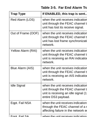
Table 3-5. Far End Alarm Trap Descriptions
Trap Type If ENABLED, this trap is sent...
Red Alarm (LOS) when the unit receives indication from the far end unit through the FEAC channel that the far end unit has lost its receive signal.
Out of Frame (OOF) when the unit receives indication from the far end unit through the FEAC channel that the far end unit has lost frame synchronization with the network.
Yellow Alarm (RAI) when the unit receives indication from the far end unit through the FEAC channel that the far end unit is receiving an RAI indication from the network.
Blue Alarm (AIS) when the unit receives indication from the far end unit through the FEAC channel that the far end unit is receiving an AIS indication from the network.
Idle Signal when the unit receives indication from the far end unit through the FEAC channel that the far end unit is receiving an idle signal (1100) over the entire DS3 payload.
Eqpt. Fail NSA when the unit receives indication from the network through the FEAC channel of a non-service-affecting failure in the network equipment.
Eqpt. Fail SA when the unit receives indication from the network through the FEAC channel of a service-affecting failure in the network equipment.
Chapter 3. Configuration
Toggle All Traps
When activated, this entry allows you to toggle ALL alarms
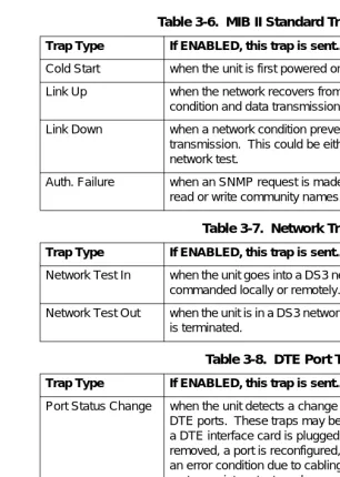
Table 3-6. MIB II Standard Trap Descriptions
Trap Type If ENABLED, this trap is sent...
Cold Start when the unit is first powered on.
Link Up when the network recovers from a Link Down condition and data transmission is restored.
Link Down when a network condition prevents data transmission. This could be either an alarm or a network test.
Auth. Failure when an SNMP request is made with the wrong read or write community names.
Table 3-7. Network Trap Descriptions
Trap Type If ENABLED, this trap is sent...
Network Test In when the unit goes into a DS3 network test, either commanded locally or remotely.
Network Test Out when the unit is in a DS3 network test and the test is terminated.
Table 3-8. DTE Port Trap Description
Trap Type If ENABLED, this trap is sent...
Port Status Change when the unit detects a change in any of the four DTE ports. These traps may be generated when a DTE interface card is plugged in, a cord is removed, a port is reconfigured, a port goes into an error condition due to cabling problems, or a port goes into a test mode.
Table 3-9. Quad DSX Port Trap Description
Trap Type If ENABLED, this trap is sent...
Chapter 3. Configuration
Figure 3-10. System Management Configuration Menu (2 of 2)
Password
Set the password required at login (up to 32 characters). The default password is adtran (all lower case).
Unit ID
Enter a name to identify the unit for management purposes.
Terminal Timeout
Set the amount of time the terminal or TELNET session can remain inactive before requiring re-entry of the password for access. This option can be disabled or set for 1 minute, 5 minutes, 15 minutes, 60 minutes, or one day.
Date/Time
Chapter 3. Configuration
by forward slashes). View this information in the STATISTICS menus.
Alarm Relay
Enable if the alarm terminal block (located on the rear of the unit) is connected to an audible alarm. If enabled, the alarm circuit is activated when a network alarm occurs.
Dialup Options
Configure the dialup capabilities of the T3SU 300. See Figure 3-11. Descriptions of the individual fields of this menu follow the figure.
Figure 3-11. Dialup Options Menu
Primary and Secondary Phone Numbers
When the T3SU 300 dials out to send a trap, it first dials the
PRIMARY PHONE NUMBER. If the call is unsuccessful, it tries the
Chapter 3. Configuration
Initializing String
The AT command entered in this field is used to initialize the modem. Normally, this field should be left at the default setting (ATZ).
Dial String
The AT command entered in this field causes the modem to dial out. Normally, this field should be left at the default setting (ATDT).
Maximum Redial Attempts
The T3SU 300 attempts to establish a call the number of times entered in this field. If a successful call is not established after the final attempt, the T3SU 300 discards the trap messages.
Idle Timeout
Once a call is established and the trap messages are sent, the T3SU 300 remains online for the amount of seconds entered in this field. If the field is set to 0, the unit hangs up as soon as the trap is sent.
Connection Timeout
The T3SU 300 waits for a connection the amount of seconds entered in this field. Timing begins as soon as the dial command is issued.
Pause Between Calls
The T3SU 300 waits the number of seconds entered in this field between redial attempts.
Dialout On Trap
Enable or disable the T3SU 300’s ability to dial out to report traps. When configured for DIALUP VT-100, the unit reports error conditions in plain ASCII with the following information: • The Unit ID value programmed in the Unit ID field of the
second SYSTEM MANAGEMENT screen (see Figure 3-10) • A trap code indicating the error condition (selected from the
Chapter 3. Configuration
• The date and time when the error was logged
When the MODEM MODE is configured for DIALUP PPP or DIALUP SLIP, the unit logs in to the PPP/SLIP host and reports the error conditions to the hosts designated under the TRAP IP ADDRESSES (also found under SYSTEM MANAGEMENT).
Answer on Ring
Enable or disable the T3SU 300’s ability to accept an incoming call. If enabled, incoming calls are automatically answered by the T3SU 300, allowing you to remotely perform management functions.
Hangup
Selecting this option forces the T3SU 300 to end an established call.
Last Modem Response
This status field displays the last modem response to the T3SU 300. Possible responses include:
OK CONNECT BUSY ERROR NO DIALTONE NO CARRIER
UTILITIES
The UTILITIES menu allows you to view T3SU 300 system information (including self-test results), revert to default
configuration settings, or flash load a new version of software. The
Chapter 3. Configuration
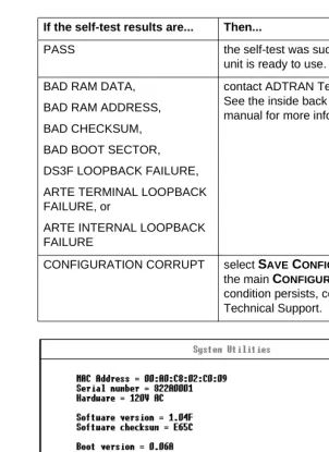
Figure 3-12. System Utilities Menu
If the self-test results are... Then...
PASS the self-test was successful and the unit is ready to use.
BAD RAM DATA,
BAD RAM ADDRESS,
BAD CHECKSUM,
BAD BOOT SECTOR,
DS3F LOOPBACK FAILURE,
ARTE TERMINAL LOOPBACK FAILURE, or
ARTE INTERNAL LOOPBACK FAILURE
contact ADTRAN Technical Support. See the inside back cover of this manual for more information.
Chapter 3. Configuration
SAVE CONFIGURATION
The SAVE CONFIGURATION selection commits the current
Chapter 4
Status
View port status information by selecting 1 STATUSfrom the MAIN menu. Information for the network port and the DTE ports is provided. The STATUS menu is shown in Figure 4-1.
Figure 4-1. Status Menu
NETWORK PORT
DS3 Framing
Chapter 4. Status
Network State
This field displays the current chart:
Alarm State
This field displays the current alarm condition of the T3SU 300. Possible conditions are given in the following chart:
Condition Description
Normal The T3SU 300 is ready to pass data.
Alarm The unit is currently receiving an alarm indication. See the ALARM STATE field in this menu to determine the alarm type.
In Test The unit is currently in test mode. The DIAGNOSTICS menu provides information on test type.
Condition Description
Normal No alarms are currently being received.
Yellow The unit is transmitting a yellow alarm from the network. This alarm is a signal sent back toward the source of a failed transmit circuit. The X-bits (X1 and X2) are set to zero.
LOS (Red Alarm) The unit has lost the Rx signal.
Blue (AIS) The unit is receiving a blue alarm condition from the network. A blue alarm occurs when consecutive 1010s are received in the information bits. This indicates that there is a transmission fault located either at or upstream from the transmitting terminal.
OOF The unit detects an out of frame condition from the network.
Chapter 4. Status
Data Link State
This field displays the current state of the data link between the local and the remote T3SU 300s. Possible states are listed in the following chart:
Remote State
This field displays the current state of the remote link. Possible states are listed in the following chart:
Condition Description
Normal The local unit’s data link is in sync with the remote unit.
Disabled The DATA LINK option in the DS3 NETWORK CONFIGURATIONmenu is set to DISABLED. Down The local and remote units are not in sync.
Condition Description
Normal No alarms are currently being received.
RAI (Yellow Alarm)
The unit is transmitting a yellow alarm from the network. This alarm is a signal sent back toward the source of a failed transmit circuit. The X-bits (X1 and X2) are set to zero.
LOS (Red Alarm)
The unit has lost the Rx signal.
AIS (Blue Alarm)
The unit is receiving a blue alarm condition from the network. A blue alarm occurs when consecutive 1010s are received in the information bits. This indicates that there is a transmission fault located either at or upstream from the transmitting terminal.
OOF The unit detects an out of frame condition from the network.
Idle The unit detects an idle sequence from the network. Service is immediately available for use.
Chapter 4. Status
DTE PORTS
The following status information is available for DTE Ports 1-4.
Interface Type
The interface type of the port is shown in this field (HSSI, V.35, or Quad DSX-1).
Port Status
This field displays the current port status. Possible states are listed in the following chart:
Eqpt Fail (NSA) The network has signaled a non-service affecting equipment failure condition.
Com Eqpt Fail (NSA)
The network has signaled a non-service affecting common equipment failure condition.
Unknown The T3SU 300 is unable to determine the state of the network or the remote unit.
Condition Description
Condition Description
Inactive The port is installed, but idle. Activate a port through the
PORT STATE field of the DTE PORT CONFIGURATION menu.
Active The port has been configured and is passing data.
Error An error condition such as loss of transmit clock has occurred.
Chapter 4. Status
T1 Status
This field displays the current status of the Quad DSX-1 interface card. Some conditions are given for each of the four individual ports, while others apply to the entire card. Possible states are listed in the following charts:
Waiting for DTE The port has been configured and is waiting for the DTE to issue the appropriate handshaking signals. For the HSSI interface, the terminal equipment available (TA) signal must be asserted by the DTE. For V.35, DTR is required if the TR field is set to IDLE WHEN OFF; otherwise, DTR is ignored. The TR field is found in the
DTE PORT CONFIGURATIONmenu.
Condition Description
Condition Description
Status conditions for an individual DSX-1 port
Off The DSX-1 port has been turned off by the user.
OK The DSX-1 port is on and is capable of passing data.
Red The DSX-1 port detects a loss of signal and is in red alarm.
OOF The DSX-1 port detects an out of frame condition from the network.
Yel The DSX-1 port detects a yellow alarm condition.
Blue The DSX-1 port detects a blue alarm condition (unframed all ones).
Chapter 4. Status
Bandwidth
Displays the amount of bandwidth being used by the port. This field does not apply to the Quad DSX-1 interface card.
DTE Leads
If a lead is active on the port, it is displayed in this field. The leads differ according to the interface type. This field does not apply to the Quad DSX-1 interface card.
Condition Description
Status conditions for the entire Quad DSX-1 card
Initializing The Quad DSX-1 interface card has just been inserted and is initializing.
Comm Error The T3SU 300 unit is unable to communicate with the Quad DSX-1 interface card. If displayed, call ADTRAN Technical Support (see inside back cover of this manual).
Frame Slip The Quad DSX-1 interface card has detected a frame slip.
PLL Error The Quad DSX-1 interface card is unable to lock on to the timing source.
Chapter 4. Status
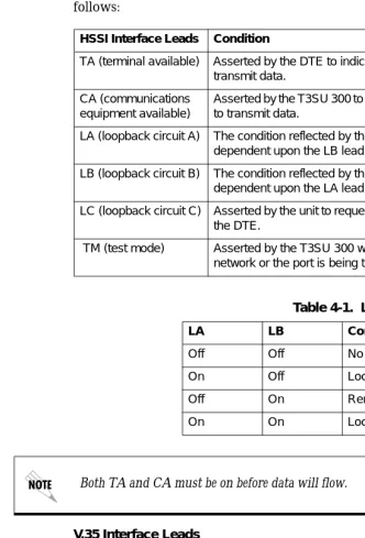
Lead descriptions for both the HSSI and the V.35 interfaces are as follows:
V.35 Interface Leads
RS: Request to send CS: Clear to send CD: Carrier detect TR: Data terminal ready
HSSI Interface Leads Condition
TA (terminal available) Asserted by the DTE to indicate readiness to transmit data.
CA (communications equipment available)
Asserted by the T3SU 300 to indicate readiness to transmit data.
LA (loopback circuit A) The condition reflected by this lead is dependent upon the LB lead. See Table 4-1.
LB (loopback circuit B) The condition reflected by this lead is dependent upon the LA lead. See Table 4-1.
LC (loopback circuit C) Asserted by the unit to request a loopback from the DTE.
TM (test mode) Asserted by the T3SU 300 when either the network or the port is being tested.
Table 4-1. LA and LB Leads
LA LB Condition
Off Off No test (normal)
On Off Local line loopback
Off On Remote line loopback
On On Local DTE loopback
Chapter 4. Status
RL: Remote port payload loopback
Chapter 5
Statistics
VIEWING STATISTICAL INFORMATION
Select 2 STATISTICSfrom the MAIN menu to access STATISTICS menus. Alarm information and performance parameters are available for both the near and far ends of the network. If a Quad DSX-1 card is installed, the menu item OTHER STATISTICSappears on the main STATISTICS screen (see Figure 5-1). This selection provides access to alarm counts for the DSX-1 ports.
All statistical information is given in screens based on the following time periods: the current 15-minute interval, a 24-hour history (divided into 96 15-minute intervals), and the totals for the previous 24 hours. Also, a cumulative alarm count is given. This count continues indefinitely until reset by the user.
Chapter 5. Statistics
Figure 5-1. Main Local Statistics Menu Screen
Alarm History
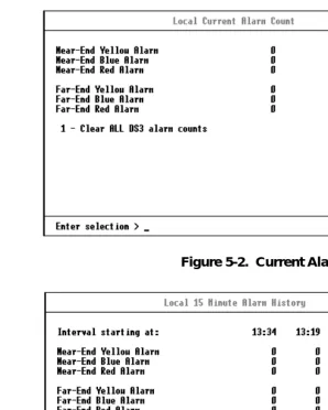
The T3SU 300 keeps track of yellow, blue, and red alarms for the near end. View alarm history information in one of the three time period selections, or view a cumulative alarm count. Information in these fields is for the given time period (if any) since the last reset. The cumulative alarm count continues indefinitely until CLEAR ALL DS3 ALARM COUNTS is selected. See Figure 5-2 and Figure 5-3 on page 5-3 for examples of alarm screens.
An alarm history is also available for the individual ports of a Quad DSX-1 interface card (if installed). Select PORTX QUAD DSX-1 ALARM HISTORY (where X is the number of the card slot that the Quad DSX-1 card is installed in). See Figure 5-4 on page 5-4 for an example of the 24-hour alarm history for the card.
Chapter 5. Statistics
Figure 5-2. Current Alarm Count Screen
Figure 5-3. 24-Hour Alarm History Screen
Chapter 5. Statistics
Figure 5-4. Quad DSX-1 24-Hour Alarm History
Performance Parameters
View performance parameter information in one of the three time period selections. Information in these fields is for the given time period since the last reset. When viewing the 24-hour history statistics screen, use the left and right arrow keys to scroll through all 96 15-minute intervals. See Figure 5-5 through Figure 5-7 for examples of the performance parameter screens.
Descriptions of each field of these screens follow:
Interval starting at:
Time that the 15-minute interval began. This field is only displayed in the 24-hour history screen which gives information for the previous 24 hours divided into 15-minute intervals (shown in Figure 5-6).
Unavailable Seconds (UAS)
Chapter 5. Statistics
Severely Errored Framing Seconds (SEFS)
Number of seconds with one or more out of frame defects or a detected incoming AIS.
Line Coding Violations (LCV)
Number of BPVs (bipolar violations) and EXZs (excessive zeros) that have occurred.
Line Errored Seconds (LES)
Number of seconds in which one or more CVs or one or more loss of signal (LOS) defects occurred.
Figure 5-5. Network Statistics Menu for Current 15-Minute Interval
P-Bit Errored Seconds (PES)
Number of seconds with one or more PCVs (P-bit coding violations), one or more out of frame defects, or a detected incoming AIS (alarm indication signal). This count is not incremented when UASs (unavailable seconds) are counted.
P-Bit Severely Errored Seconds (PSES)
Chapter 5. Statistics
P-Bit Coding Violations (PCV)
Number of coding violation (CV) error events that have occurred.
C-Bit Coding Violations (CCV)
In C-bit parity mode, this is a count of coding violations reported via the C-bits or the number of C-bit parity errors that have occurred.
Figure 5-6. Network Port Statistics 24-Hour History Screen
C-Bit Errored Seconds (CES)
Number of seconds with one or more CCVs, one or more out of frame defects, or a detected incoming AIS. This count is not incremented when UASs are counted.
C-Bit Severely Errored Seconds (CSES)
Number of seconds with 44 or more CCVs, one or more out of frame defects, or a detected incoming AIS. This count is not incremented when UASs are counted.
F-Bit Errors (FBE)
Chapter 5. Statistics
M-Bit Errors (MBE)
Number of times an M-bit framing error has occurred.
Figure 5-7. Network Port Statistics Menu (24-Hour Totals)
Clear All Local DS3 Statistics/Refresh All Remote Statistics
Chapter 6
Diagnostics
The DIAGNOSTICS menu allows you to initiate loopback and BERT tests from the T3SU 300. Figure 6-1 shows the main DIAGNOSTICS menu. Perform tests for the entire DS3 or for an individual DTE port. If a Quad DSX-1 card is installed, activate loopback tests for an entire card (all four DSX-1s) or for an individual DSX-1 port. To choose a DTE port from the left column of the menu, select the port’s corresponding number and press Enter. The individual port menus provide loopback and BERT selections. BERT configuration options and results are given in the right column of the main
DIAGNOSTICS menu.
Diagnostic selections are described in the following portions of this chapter:
DS3 Options: page 6-2 through page 6-4
HSSI and V.35 Port Options: page 6-4 through page 6-7
Quad DSX-1 Interface Card Options: page 6-8 through page 6-13 BERT Configuration Options: page 6-14 through page 6-15
You can only perform a BERT test on one DTE port at a time. If a BERT test is already in progress and a second BERT test is selected for another port, the first test is discontinued.
Chapter 6. Diagnostics
Figure 6-1. Diagnostics Main Menu
DS3
Access the DS3’s diagnostic options by selecting 1 from the main
DIAGNOSTICS menu. The menu in Figure 6-2 appears.
Chapter 6. Diagnostics
Data Mode
Ends a test already in progress for this port.
DS3 Payload Loopback
During this test, all payload information is re-framed and looped back towards the network. See Figure 6-3 for a block diagram illustrating the loopback point and the signal paths for this test.
Figure 6-3. DS3 Payload Loopback Test
Line Loopback
This test allows the loop interface (LINE) section of the local T3SU 300 to be tested from the remote T3SU 300 over the actual T3 circuit. Testing from the remote end of the circuit is performed by using a 511 test pattern or DTE data generated by the remote host. With this test, the T3SU 300 transceiver receives data from the network and loops it back toward the network through its transmitter. The transmitted data is identical to the receive data (including framing errors) and can therefore be accurately tested by the carrier for errors. See Figure 6-4.
This test does not interrupt data flow from the network to the DTE, but it does block all DTE-to-network data.
DTE
T3SU 300
Chapter 6. Diagnostics
Figure 6-4. Line Loopback Test
BERT
Select BERT to perform a bit error rate test over the entire payload bandwidth. Only one BERT test may be performed at a time.
Remote DS3 Loopback
This selection initiates a DS3 Loopback test for the remote unit. The DS3 Loopback test is described on page 6-3.
Remote Loopback with BERT
This selection initiates a DS3 Loopback test for the remote unit and sends/checks the BERT pattern over the entire DS3 payload bandwidth.
DTE Ports 1-4
Access the DTE port diagnostic options by selecting the number corresponding with the desired port (options 2 through 5) from the main DIAGNOSTICS menu. These options differ depending on the interface type of the selected port. See the following section for the testing options available for the HSSI and V.35 ports. See the section Quad DSX-1 Diagnostic Options on page 6-8 for testing options available for the DSX-1 ports.
DTE
Chapter 6. Diagnostics
HSSI and V.35 Diagnostic Options
The menu in Figure 6-5 appears if the selected DTE port is HSSI or V.35. Descriptions of the menu selections follow the figure.
Figure 6-5. HSSI or V.35 Port Diagnostics Menu
Data Mode
Ends a test already in progress.
Payload Loopback
This selection initiates a PAYLOAD LOOPBACK test for all data on the selected port rather than for the entire DS3. During this test, the data is looped back in the network direction. Perform this test to verify the integrity of the portion of the DS3 link connecting the selected port of the T3SU 300 and the remote DTE. This test is non-intrusive to the three other ports. See Figure 6-6.
Chapter 6. Diagnostics
Figure 6-6. Payload Loopback Test
Payload BERT
This selection performs a bit error rate test on the selected port. This test in non-intrusive to the other three ports. Only one BERT test may be performed at a time. This test is normally performed from the remote and local ends simultaneously to determine whether the errors are coming from the transmit or the receive direction. See Figure 6-7.
Figure 6-7. Payload BERT Test
DTE Loopback
This test is used to verify proper operation of the link between the T3SU 300 and the terminal equipment. During this test, all data sent by the terminal equipment is looped back to the terminal equipment. A block diagram illustrating the loopback point and the signal path is shown in Figure 6-8.
DTE
MUX T3SU 300
BERT OUT
BERT IN DTE
MUX
T3SU 300
Chapter 6. Diagnostics
Figure 6-8. DTE Loopback Test
Payload and DTE Loopback
Select this test to perform payload and DTE loopbacks
simultaneously. The individual tests are described on page 6-3 and page 6-6. See Figure 6-9 for a block diagram illustrating this test.
Figure 6-9. Payload and DTE Loopback Test
Remote Port Payload Loopback
This selection initiates a Payload Loopback on the remote T3SU 300 for all data on the selected port. Perform this test to verify the integrity of the portion of the DS3 link connecting the local DTE and the selected port of the remote T3SU 300. All other ports on both the local and remote units are unaffected.
Remote Payload Loopback with BERT
Perform this test to verify the integrity of the link between the selected port of the local T3SU 300 and the corresponding remote T3SU 300 port. During this test, the remote unit loops back all data for the selected port, while the local unit sends and checks the selected BERT pattern. The loopback point and the signal paths for
DTE
MUX T3SU 300
DTE
Chapter 6. Diagnostics
the remote T3SU 300 are the same as the Payload Loopback test for the local T3SU 300 (shown in Figure 6-6).
Quad DSX-1 Diagnostic Options
The menu in Figure 6-10 appears if the selected port is a Quad DSX-1. Descriptions of the menu selections follow the figure.
Figure 6-10. Quad DSX-1 Diagnostics Menu
Data Mode
Chapter 6. Diagnostics
#x Payload Loopback
During this test, all payload information on the selected DSX-1 interface