ABSTRACT
ZIMMER, CHRISTOPHER J. Bringing Efficiency and Predictability to Massive Multi-core NoC Architectures. (Under the direction of Frank Mueller.)
Massive multi-core network-on-chip (NoC) processors represent the next stage in both em-bedded and general purpose computing. These novel architecture designs with abundant pro-cessing resources and increased scalability address the frequency limits of modern processors, power/leakage constraints, and the scalability limits of system bus interconnects. NoC archi-tectures are particularly interesting in both the real-time embedded and high-performance com-puting domains. Abundant processing resources have the potential to simplify scheduling and represent a shift away from single core utilization concerns e.g.,within the model of the “dark silicon” abstraction that promotes a 1-to-1 task-to-core mapping with frequent core activa-tions/deactivations. Additionally, due to silicon constraints, massive multi-core processors often contain simplified processor pipelines that provide an increase in predictability analysis bene-ficial for real-time systems. Also, simplified processor pipelines coupled with high-performance interconnects often result in low power utilization that is beneficial in high-performance sys-tems. While suitable in many ways, these architectures are not without their own challenges. Reliance on shared memory and the strain that massive multi-core processors can put on mem-ory controllers represent a significant challenge to predictability and performance. Resilience is another concern when using NoC processors due to decreased fabrication size.
The aim of this work is to overcome the efficiency, predictability, and resiliency challenges present in massive multi-core architectures. We present new approaches to improve on each of these aspects.
1. First, this work contributes a new real-time paradigm called Forte designed to overcome resilience and predictability challenges. In Forte, we eliminate shared memory use and replace it using TDMA-based explicit communication for increasing predictability. We then extend the traditional task model to introduce the notion of multi-mode data streams to support redundant job execution. This is used to explicitly check coherence ranges of concurrent jobs. Coherence is ensured by protecting against single event upsets and enabling the use of data rejuvenation to increase the mean time to failure of the overall system.
task-to-core mappings that aid in decreasing communication contention. We provide two solvers, an optimal and a multi-heuristic solver to quickly and efficiently model inter-task communication and to choose the best layouts that improve predictability of the system. We also provide an automatic framework for evaluating the effects of temporally framed communication on an actual NoC processor using the underlying hardware for explicit message passing.
3. Third, we extend the previous research into a new message-passing library based on MPI by fundamentally designing it for hardware-based network-on-chip strategies. This work compares real-world high-performance benchmarks and shows true application-level scalability limits of shared memory on processors with significant core counts. We then put forth a phase-based optimization strategy that optimizes communication of NoC architectures by eliminating the use of flow control and show significant improvements when compared with current state of the art message passing implementations for network-on-chip processors.
c
!Copyright 2013 by Christopher J. Zimmer
Bringing Efficiency and Predictability to Massive Multi-core NoC Architectures
by
Christopher J. Zimmer
A dissertation submitted to the Graduate Faculty of North Carolina State University
in partial fulfillment of the requirements for the Degree of
Doctor of Philosophy
Computer Science
Raleigh, North Carolina
2013
APPROVED BY:
Alex Dean Xuxian Jiang
Vincent Freeh Frank Mueller
BIOGRAPHY
Christopher John Zimmer was born on May 28th, 1982 in Worthington, Minnesota. He attended Naples High School in Naples, Florida and graduated in 2000.
He studied Computer Science at Florida State University receiving a Bachelor of Science in 2004 and a Master of Science in 2006.
ACKNOWLEDGEMENTS
I would like to thank Frank Mueller, to his credit over the course of four years he tried and tried to teach me to write a proper sentence. In the end upon giving up teaching me how to write, we instead decided to focus on technical challenges. Your open-door policy and availability far exceeded what I could have expected as a graduate student. Your guidance was invaluable and our disagreements were constructive. Thank you again.
Antonia, thank you for your patience, I don’t know how many times I fretted that I wasn’t going to succeed. It didn’t matter, you always patted me on the back and placated my irrational anxieties. You’re a spectacular partner in this walk through life.
Mom and Dad, your support was unwavering, it was all I could have asked for. You believed in me even when I didn’t, sappy I know but astonishingly accurate. Thank you so much.
Emmerson, thank you for holding my hand and insisting I go down the slides with you. You have no idea how many bad days that made better.
Fellow inmates, Abhik, Yongpeng, Xing, David, Arash, and James. Keep up the inane banter, it is paramount in maintaining sanity in this stressful environment. However, take the soccer ball outside for once.
TABLE OF CONTENTS
List of Tables . . . vi
List of Figures . . . vii
Chapter 1 Introduction . . . 1
1.1 Network-On-Chip Architectures . . . 1
1.2 Real-Time Systems . . . 3
1.2.1 Definition of a Real-Time System . . . 4
1.2.2 Timing Analysis . . . 4
1.2.3 NoC Real-time Systems . . . 5
1.2.4 Challenges of Massive Multi-core Real-time Systems . . . 5
1.3 High Performance Computing . . . 5
1.3.1 Multi-Computer vs NoC . . . 5
1.3.2 High Performance Challenges . . . 6
1.3.3 Contributions . . . 6
1.3.4 Hypothesis . . . 7
1.3.5 Organization . . . 8
Chapter 2 Network-On-Chip Predictability Challenges . . . 9
2.1 Introduction . . . 9
2.2 Forte Design . . . 11
2.2.1 Shadow Tasks . . . 14
2.2.2 Input . . . 14
2.2.3 Output . . . 15
2.2.4 TDMA . . . 16
2.2.5 Task Rejuvenation . . . 17
2.3 UAV Application . . . 18
2.3.1 Paparazzi Autopilot-Base Design . . . 19
2.3.2 Fly-By-Wire Base Design . . . 19
2.4 Forte Implementation . . . 20
2.4.1 Input and Output Tasks . . . 21
2.4.2 Scheduler . . . 22
2.4.3 Fault Models . . . 22
2.4.4 Coherence Checks . . . 22
2.4.5 Rejuvenation . . . 23
2.5 Experimental Framework . . . 23
2.6 Experimental Results . . . 24
2.7 Related Work . . . 29
Chapter 3 Low Contention Mapping of Real-Time Tasks onto a TilePro 64
Core Processor . . . 33
3.1 Introduction . . . 33
3.2 Software-Based Temporal Framing . . . 35
3.3 Motivation . . . 36
3.4 Exhaustive Solver Model . . . 39
3.5 Heuristic Model . . . 41
3.5.1 Task Mapping Heuristics . . . 42
3.5.2 Core Mapping Heuristics: . . . 42
3.6 Micro-Benchmark . . . 43
3.7 Results . . . 45
3.8 Related Work . . . 55
3.9 Conclusion . . . 56
Chapter 4 NoCMsg: Scalable NoC-Based Message Passing . . . 57
4.1 Introduction . . . 57
4.2 Motivation . . . 58
4.3 Design . . . 60
4.3.1 NoC Architecture . . . 60
4.3.2 Cores . . . 60
4.3.3 Switches . . . 61
4.3.4 Back pressure Checking via Credit Monitoring . . . 62
4.4 Implementation . . . 63
4.4.1 Point-to-Point Messages . . . 64
4.4.2 Collectives . . . 66
4.4.3 Barriers . . . 66
4.4.4 Network Partitioning . . . 67
4.5 Framework . . . 67
4.6 Experimental Results . . . 68
4.6.1 Microbenchmarks . . . 68
4.6.2 NAS Parallel Benchmarks . . . 71
4.6.3 Flow Control Elimination . . . 73
4.6.4 FPU Experiments . . . 77
4.7 Related Work . . . 80
4.8 Conclusion . . . 82
Chapter 5 Future Work . . . 86
5.0.1 Operating System Abstractions . . . 86
5.0.2 Trade-OffAssessment of Hybrid Programming Models . . . 87
5.0.3 NoC Partitioned Scheduling and Load Balancing . . . 88
5.0.4 Run-time Contention Avoidance . . . 89
5.0.5 Memory Controller Aware Provisioning . . . 89
LIST OF TABLES
Table 2.1 Fault Injection Evaluation . . . 25
Table 2.2 Rejuvenation: Time to Full Restart . . . 26
Table 3.1 Average Solving Times [hh:mm:ss.ms] . . . 47
Table 3.2 Solving Times per Task Set for a 4x4 Mesh [hh:mm:ss.ms] . . . 50
LIST OF FIGURES
Figure 1.1 Abstract Bus Architectures . . . 2
Figure 2.1 Forte Task Layout Over Cores . . . 12
Figure 2.2 Abstract Task Layout After Splitting . . . 13
Figure 2.3 Task Chaining . . . 14
Figure 2.4 Data Stream Abstraction . . . 15
Figure 2.5 Paparazzi Design . . . 18
Figure 2.6 Auto Pilot Task and Data Flow . . . 20
Figure 2.7 Fly-By-Wire Task and Data Flow . . . 21
Figure 2.8 Paparazzi Task Layout . . . 24
Figure 2.9 Overhead of Coherence: Shared Memory vs. Message Passing . . . 26
Figure 2.10 Climb Control Task Jitter: Shared Memory vs. Message Passing . . . . 27
Figure 2.11 Bulk Transfer Overhead: Shared Memory vs. Message Passing . . . 28
Figure 2.12 Bulk Transfer Jitter: Shared Memory vs. Message Passing . . . 29
Figure 2.13 Scaling Contention: Shared Memory vs. Message Passing . . . 30
Figure 3.1 NoC Contention (Config 1) . . . 34
Figure 3.2 Temporal Framing Example . . . 36
Figure 3.3 Contended Network Resource (Config 2) . . . 37
Figure 3.4 Zero Cost Network Layout (Optimal) . . . 38
Figure 3.5 Contention Related Jitter . . . 38
Figure 3.6 Temporal Framing Graph . . . 39
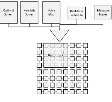
Figure 3.7 Tilera Evaluation Framework . . . 44
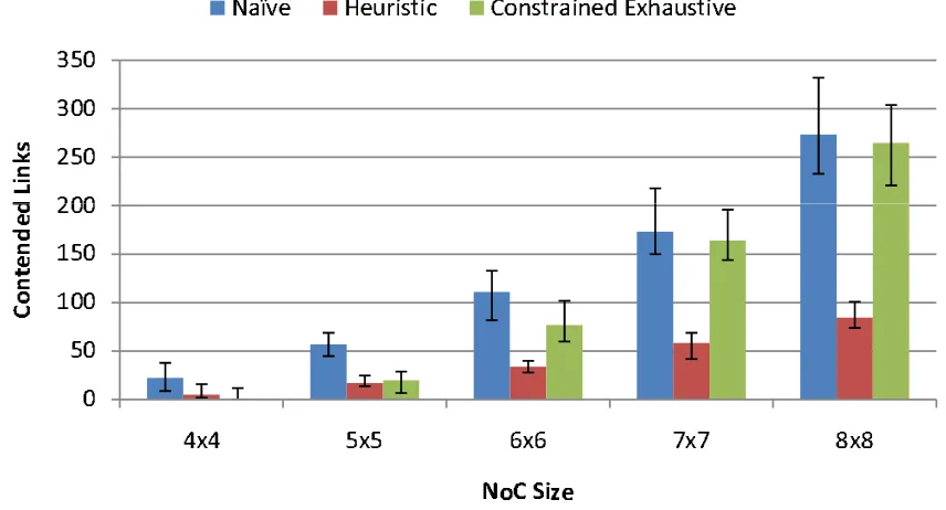
Figure 3.8 Average Contention for Mapping Strategies . . . 46
Figure 3.9 Percent Use of Core Selection Strategies . . . 48
Figure 3.10 Percent Use of Task Selection Strategies . . . 49
Figure 3.11 Contention Jitter on a 4x4 NoC . . . 49
Figure 3.12 Jitter as a Percentage of Worst Case Transfer Time on a 4x4 NoC . . . 51
Figure 3.13 Scatter Send One to One on a 4x4 NoC . . . 51
Figure 3.14 Scatter Receive One to One on a 4x4 NoC . . . 52
Figure 3.15 Scatter Send Two to One on a 4x4 NoC . . . 53
Figure 3.16 Scatter Receive Two to One on a 4x4 NoC . . . 54
Figure 4.1 Message Passing Deadlock . . . 59
Figure 4.2 Core - Switch Topology . . . 61
Figure 4.3 Path-Based Back Pressure . . . 62
Figure 4.4 Profile Detected Communication Regions . . . 65
Figure 4.5 Shared Memory/Messages NoC Bandwidth . . . 69
Figure 4.6 Shared Memory/Messages NoC Jitter [1MB Transfer] . . . 70
Figure 4.7 NPB LU: Weak Scaling . . . 72
Figure 4.8 NPB SP: Weak Scaling . . . 73
Figure 4.10 NPB FT: Weak Scaling . . . 75
Figure 4.11 NPB MG: Weak Scaling . . . 76
Figure 4.12 NPB IS: Weak Scaling . . . 77
Figure 4.13 NPB FT: NoCMsg vs. Opera MPI . . . 78
Figure 4.14 NPB CG: NoCMsg vs. Opera MPI . . . 79
Figure 4.15 NPB IS: NoCMsg vs. Opera MPI . . . 80
Figure 4.16 TF*IDF: OpenMP vs NoCMsg . . . 81
Figure 4.17 TF*IDF: NoCMsg vs OperaMPI . . . 82
Figure 4.18 LU Native Weak Scaling . . . 83
Figure 4.19 SP Native Weak Scaling . . . 84
Figure 4.20 CG Native Weak Scaling . . . 84
Figure 4.21 FT Native Weak Scaling . . . 85
Figure 4.22 MG Native Weak Scaling . . . 85
Chapter 1
Introduction
1.1
Network-On-Chip Architectures
Systems architecture is in a constant state of change. The frequency wall [23] has led to the use of multi-core processors and major changes in software architectures. Prior to multi-cores, software threading using time-slicing or cooperative techniques only had to consider memory access from a single processor. With the advent of symmetric multi-cores, interconnect contention increased due to cache coherence traffic. This change affected several areas of computing. In general, greater contention resulted in overheads that were offset by improved performance, particularly in applications that could take advantage of extra hardware pipelines. Nonetheless, interconnect contention led to perturbation that was unacceptable in many real-time systems. However, continuously rising processing demand has required the development of new interconnects and memory layouts.
no waiting for bus access. Instead, NoC accesses result in non-uniform latencies caused by hop-count variations and, more importantly, contention-based delay experienced at the switching level.
A Front Side Bus B Network on Chip
Figure 1.1: Abstract Bus Architectures
A major challenge that NoC designers face today to accommodate the legacy of shared memory software. To be precise, when this work refers to shared memory, it is referring to the abstraction created in software that implements the notion of data sharing between threads/processes. This abstraction requires dedicated hardware resources in order to work properly. Cores are designed around large cache hierarchies and the NoC is optimized to per-form cache-to-cache transfers. These features require hardware for tracking coherence states of shared data. A widely used coherence protocol, MOESI, maintains five states for tracking shared data.
• Modified, which means the data is dirty but the local copy is correct and exclusive;
• Owner, which means the cache line is shared but its home is the local cache, containing clean data while shared copies are dirty;
• Exclusive, which means the data is clean in both other caches and memory;
• Shared, which means the data is clean in shared caches but not in memory;
• Invalid, which means the cache line does not contain a valid copy of the data.
running a single application. Cache access hops in the NoC play a large role in the design as architects want to limit expensive long distance updates. In the 100 core case, a worst case access could require up to 36 hops through the network to request and receive the desired value. Due to this cost, a generic design may consider using local cache-line copies to avoid remote cache accesses for each read. This results in a separate, more expensive coherence network.
Additional costs in using shared memory in NoCs come through the necessity of synchroniza-tion to avoid race condisynchroniza-tions or data hazards such as atomics, barriers, or locks. The problem is exacerbated when we consider that we are no longer synchronizing 2 or 4 cores but rather 64 to 100 cores. System designers put great effort into designing system-wide high-performance techniques for improving synchronization. These techniques may include implementing sys-tems for locking synchronization objects into a single cache and optimizing native atomics to improve access times to this data. Other techniques may involve vendor-provided libraries to best take advantage of the hardware interfaces. Unfortunately, all of these techniques still result in limited scalability for legacy code.
As the core counts increase, current system and programming abstractions, such as pure task-level parallelism, become an obstacle rather than an aid in harnessing multi-core power. Design trends in NoC lend to software reuse through shared memory. Unfortunately, limitations of shared memory are already proving to be the next performance bottleneck in existing systems containing 32 and 64 cores. Next generation NoC architectures are being designed to contain hundreds (if not thousands) of cores to meet processing demands. Fortunately, NoCs also offer a novel paradigm of on-chip message passing. The focus of this dissertation is identifying techniques for taking advantage of on-chip message-passing. In this work, we focus on real-time and high-performance computing.
1.2
Real-Time Systems
Real-time systems are a technology domain in which the design of the system focuses on guaran-teeing temporal correctness. This means that real-time systems focus on the ability to guarantee that running software will finish within precise timing thresholds. This differs from traditional systems where the primary metric is performance. Real-time systems are often obfuscated from view but enable important functions that humans rely on. An example can be seen in anti-lock braking systems, which constantly monitor our car brakes and must react within certain amounts of time to guarantee that the brakes do not lock up. Real-time control systems are ubiquitous and increasingly demand new technologies to meet increased requirements.
categories of real-time systems based on the implications of systems correctness for deadline misses. Soft real time indicates that a deadline can be missed without rendering the system incorrect. However, the later a result is provided after a deadline, the more likely it is to reduce the systems quality of service. Hard real time indicates that a miss of a deadline results in an incorrect system. Hard real-time systems encompass a class of systems known as safety critical. In such systems, missing a deadline could result in damage to the environment and even loss of life.
1.2.1 Definition of a Real-Time System
A periodic real-time system is defined as a set of tasks where each task is represented by
τ =<φ, p, e, d >.
1. φrepresents the phase of a task or the release time,
2. p represents the period of a task, i.e., the minimum time between job releases,
3. erepresents the worst-case execution time (WCET) and
4. drepresents the deadline, i.e., the time instant by when the job must be finished.
Compositions of real-time tasks are analyzed using schedulability analysis to ensure that each job in a system can execute within their respective deadlines.
1.2.2 Timing Analysis
1.2.3 NoC Real-time Systems
Massive multi-core architectures contain features that may be beneficial to the domain of real-time systems. Commercial offthe shelf (COTS) components can be used to reduce development time. Processor cores are utilizing simpler designs to increase power efficiency that also lend well to simplified modeling for static analysis. Finally, NoCs contain abundant and cheap processing resources that can relax the need for sophisticated schedulers and lead to simplified schedulability analysis, particularly when the number of processors exceeds the number of tasks in the system. This fits well into the paradigm laid out in [21] where the concept of dark silicon is introduced. Dark silicon is the notion that we are quickly reaching the threshold in which we can possibly power and cool all of the cores on a single die. Instead of powering all of them, each core will be bound to a single task. It will be the responsibility of the scheduler to execute tasks through core activations and deactivations.
1.2.4 Challenges of Massive Multi-core Real-time Systems
Today’s NoC processors can contain up to 100 processors on a single die/socket with 4 memory controllers. Over-provisioning these memory controllers and the cost of non-uniform memory la-tencies can have adverse effects in terms of predictability. Decreases in fabrication size increases the need for software based resilience for these control systems to operate safely. Task place-ment in NoC architectures can lead to increases in worst-case behavior due to inter-processor communication contention. As such, task-to-core layout is an important factor in implementing real-time systems on these processors.
1.3
High Performance Computing
High performance computing (HPC) utilizes a class of applications that can generally be defined as highly parallelizable. A major challenge facing the HPC environment is powering and cooling large machines. NoC systems offer interesting architectural features because these processors contain low power processing elements and high-speed interconnects. Another major benefit of these architectures is that they contain both message passing and shared memory features. This allows for significant reuse of HPC codes without having to fundamentally redesign algorithms.
1.3.1 Multi-Computer vs NoC
exist that separate these systems. The most significant is that NoC message passing is architec-tural in nature. Instead of requiring multiple software hierarchies involving operating systems and network interface cards, NoCs facilitate message passing through ISA instructions and reg-ister to regreg-ister transfers. This subtle difference eliminates software overhead and results in low latencies. However, this level of access may result in deadlocks within the NoC or pollution of the network with malformed packets.
1.3.2 High Performance Challenges
The major challenges that HPC faces with NoC is in defining which inter-processor communi-cation paradigm to use and determining how to take advantage of on-chip message passing in a manner suitable to the software algorithms. Traditional HPC software is written in a manner in which deadlock and flow-control considerations are abstracted from the designer. Unfortu-nately, current generation NoCs are designed for throughput while maintaining flow control and avoiding deadlocks are burdens placed on the designer. To properly take advantage of message passing abstractions, portable techniques for message passing IPC must be designed without limiting system scalability.
1.3.3 Contributions
This dissertation assess the impact of shared memory in both real-time and high-performance applications.
1. In Chapter 2 [84], we assess the impact that shared memory has on scalability and use this to motivate a new task paradigm for highly reliable real-time systems. In this work we present Forte, a real-time task system based loosely stream data flow applications. Forte breaks task computation into logical parts and promotes message passing for inter-process communication. By harnessing the increased scalability attained through message passing we can directly translate this into a system that enables high software reliability through the use of multiple concurrent task models without affecting temporal correctness when additional tasks are added to the system.
to scale to current industry size and present a series of heuristics for quickly converg-ing on solutions that reduce contention. To improve upon local minima often associated with greedy algorithms, we apply a multi-heuristic approach to improve solutions. Re-sults show a significant reduction in link contention across our generated task sets when compared with naive layouts.
3. In Chapter 4, we extend our work to the performance domain and consider how the effects considered in the previous work extend to high performance applications. We present a new framework, NoCMsg, for message passing that serves two purposes. First, it borrows semantics from MPI, a well established message passing API, to take advantage of a large amount of code already written in MPI. Second, we abstract out considerations of the hardware from the user such as flow-control management. In this work, we present a technique based off hardware analysis for circumventing deadlocks in NoC switches without having to use mixed protocol messages with interrupts as was done previously. We then identify communication patterns existing on both point-to-point and collective-based communication that enable the relaxation of any type of flow control to gain performance. Our results compare NAS Parallel benchmark codes and TF*IDF using OpenMP and Opera MPI, they show significant performance improvements when using NoCMsg.
1.3.4 Hypothesis
Processor technology has reached the scalability limit of existing on-chip resources. This will affect the advancement of several computational domains. With the increasing demands of both high-performance and real-time computations, tech-niques must be devised to avert the limits of scalability. These limitations are claimed to be caused by inter-processor communication. Current IPC techniques suffer from
1. coherence state distribution and delays,
2. request/response based IPC for all requests, and 3. contention at cache and memory controllers.
Shared memory is the fundamentally limiting technology for scalability of applica-tions exhibiting significant inter-processor communication.
The hypothesis is as follows:
1.3.5 Organization
Chapter 2
Network-On-Chip Predictability
Challenges
2.1
Introduction
ASIC-based cyber-physical systems are costly to design in terms of time and money. Multi-core COTS processors are becoming increasingly used in the high-end handheld market and are also seeing increased use in the lower-end embedded control market. An example is the Freescale 8-core PowerPC P4080 that is being marketed in the power utility domain for control devices. In such processors, traditional software design techniques coupled with increasingly smaller transistor sizes can negatively affect the real-time predictability and the fault reliability. Pre-dictability challenges in multi-cores are due to non-uniform memory latencies [46] as contention on buses and mesh interconnects increases.
Another trend is an increase in transient faults due to decreasing fabrication sizes. These faults surface as single event upsets (SEU) that can render computation incorrect. SEUs are faults that can modify logic or data in systems leading to incorrect computational results or software system corruption, which can result in temporary or even permanent incorrect actuator outputs in control systems if not countered. SEUs have three common causes: (1) Cosmic radiation, particularly during solar flares, (2) electric interference in harsh industrial environments (including high temperatures, such as in automotive control systems) and (3) ever smaller fabrication sizes and threshold voltages leading to increased probabilities of bit flips (for all) or cross-talk (for the latter) within CMOS circuitry [18, 71].
processors without hardware protection against soft errors, such as the PowerPC 750. Even though these planes are specifically designed to fly over the North Pole where radiation from space is more intense due to a thinner atmosphere, processors deployed on these aircraft lack error detecting/correcting capabilities. Hence, system developers have been asked to consider the effect of single-event upsets (SEUs),i.e., infrequent single bit-flips, in their software design. In practice, future systems may have to sustain transient faults due to any of the above causes. COTS architectures are not specifically designed for real-time fault tolerance and contain few hardware-based fault mitigating mechanisms, such as processor radiation hardening. Previously, researchers have designed techniques to mitigate SEUs in software using task scheduling [29, 24, 17]. This often leads to sophisticated scheduling techniques utilizing alternate algorithms, re-execution, or replication. In contrast, we argue that massive multi-cores with NoC interconnects greatly simplify scheduling and allow high levels of replication.
In a system with replication of entire task sets under the traditional shared-memory model, considerable strain is placed on memory controllers due to compounded memory pressure and coherence traffic resulting in contention. This contention limits scalability and reduces pre-dictability of advanced multi-core architectures. In spite of the potential drawbacks, multi-core COTS processors remain quite attractive for real-time systems. For example, ARM promotes “dark silicon” each real-time task is mapped to a separate core as cores are plentiful [21]. Scheduling then amounts to simple core activation thereby eliminating context switching costs and preemption delays. Such an abstraction also facilitates parallel, replicated execution and voting in n-modular redundant environments to increase reliability.
opposed to a scheme without rejuvenation, as shown in experiments.
The remainder of this paper is structured as follows. Section 2 presents the design of our proposed framework. A case study developing an unmanned air vehicle control system is detailed in Sections 3 and 4. Section 5 provides the experimental framework. Section 6 presents experimental results. Related work is discussed in Section 7. The paper is summarized in Section 8.
2.2
Forte Design
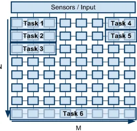
This section provides an overview of the Forte framework to exploit massive multi-core proces-sors to facilitate highly redundant cyber-physical systems. Careful use of this technique can improve system integrity in the form of protection from soft errors by providing a framework for running multiple concurrent versions of a task, called shadow tasks, and verifying their output coherence. The framework assumes that each task is permanently assigned to a unique set of cores and that the number of tasks in the system is less than the number of cores. The scheduling system is periodic with dynamic priorities based on relative deadlines. (Notice that scheduling amounts to activation/deactivation of tasks as only one task may be assigned to a core in our abstraction. Hence, we honor the periodicity of real-time tasks, yet scheduling becomes trivial as preemption never needs to occur.) Figure 2.1 depicts our model of a mas-sive multi-core NoC processor. Our sample processor model contains 64 processing elements connected in a mesh grid. Each processing element contains a switch so that network communi-cation and routing can be handled without additional overhead to the processing pipeline. NoC processors often support both static and dynamic message routing. Due to this, our framework operates agnostic of the underlying message passing API.
Figure 2.1: Forte Task Layout Over Cores
each model’s output data. To formalize the framework, we extend the classic task model such that:
τ =< I, O, T, C, R > (2.1)
• I is the set of inputs ifor them shadow tasks inT;
• O is the set of outputso ofτ that must be validated for coherence prior to allowing the output change on the system to take effect;
• T is the sequence of shadow tasks < t1, t2, .... , tm > where each element ti in T is ordered by a descending complexity coefficient ki such thatk1≥k2 ≥..≥km;
• C is the set of coordinates< x1, y1 >, < x2, y2 >that enable the system to bound τ to a
specific core within the architecture;
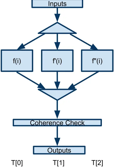
The Forte framework characterizes each task within the system with a set of inputs and outputs. Figure 2.2 depicts a Forte task where the input phase splits the data so that three redundant tasks of f can operate on separate models of the input data in parallel. We use the term f to describe the defining function(job) of the real-time task. When a task finishes execution it then sends the outputs to a coherence check that determines the correct output for the system. These sets allow tasks to execute independently or to be chained together to facilitate data flow within the system. Figure 2.3 depicts how the various tasks communicate data without using shared memory. The model forms an abstract chain: Once a task generates output data, its output data becomes the input data for a subsequent task. This model can be implemented on NoC architectures through explicit message passing.
IL IL IL
,QSXWV
7>@ 7>@ 7>@ 2XWSXWV
&RKHUHQFH&KHFN
,
I
I
FKHFN
2>@ 2>@
I I
7DVN$
FKHFN
2>@ 2>@
7DVN%
Figure 2.3: Task Chaining
2.2.1 Shadow Tasks
Forte is designed to exploit the high-level of concurrency that NoC architectures provide. Cyber-physical systems deployed in harsh environments are subject to Single Event Upsets (SEUs). These are compelling reasons to utilize the multi-core paradigm and generate several models of a single task called shadow tasks, which improves the level of data integrity of the system. In the previous example from this section,c,cshadow,s, andsshadow are considered shadow tasks of a single system level task τ. In Forte, shadow tasks are represented in a complexity ordered list. To state this more formally, for each shadow taskti inT, there is a complexity coefficient ki, such that
< ti, ti+1, ..., tm>=⇒ ki≥ki+1 ≥...≥km (2.2)
The complexity coefficientkiis best generalized as a scoring value generated by deriving less precise real-time task models from the most sophisticated design. A degraded complexity model for real-time systems was put forth in [59]. In this work, a complex and a simple feature set for a given control task helped to increase the model safety. Deriving a score forki considers effects of a reduction in features and reductions in data precision or utilization for faster converging algorithms with a larger tolerance range#.
2.2.2 Input
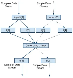
tasks. Forte considers multiple data streams separated by complexity, shown in Figure 2.4. Streams enable shadow tasks of varied complexity to ensure that data is not unnecessarily losing precision by forcing a single stream of data.
In practice, input acquisition is a precondition for each task in Forte. If the input is derived from a sensor or other external hardware, it requires one of the shadow tasks to acquire the data and then distribute the data over the message passing network. If the input is derived from the output of another task, each of the shadow tasks must receive their input from a proceeding output of equivalent data complexity.
&RPSOH['DWD 6WUHDP
6LPSOH'DWD 6WUHDP
LQSXWL>@ LQSXWL>@
W>@ W>@ W>@ W>@
&RKHUHQFH&KHFN
R>@ R>@
&RPSOH['DWD
6WUHDP 6LPSOH'DWD6WUHDP
Figure 2.4: Data Stream Abstraction
2.2.3 Output
the code in control tasks to defer a decision until the shadow task decisions can be verified. Coherence formulations are determined by the system designer. Automatically identifying how to determine these is algorithm specific.
For a given task set, each shadow task operates on local data sets. Upon completing the necessary computation, the data is checked by the coherence-checking phase of the task. This may be performed by every shadow task or in a subset of them to reduce the data transfer cost. In the coherence check in Figure 2.4, shadow taskst[1] andt[2] are of equal complexity and the data must match exactly. The same holds fort[3] andt[4]. When this verification is complete, a range check is performed to validate that the data in the complex and simple streams are within a preset range. Certain features of the complex stream may not exist in a lower precision model. This makes it important to maintain multiple checks for each level of complexity. Successful coherency checks result in the mapping of output data to locations designated by complexity. This allows subsequent tasks dependent on this output to be mapped to the data of matching complexity. If the coherency checks fail, the failing task can be isolated to remove any impact it may have on the control system. If the failure is within the highest complexity model, subsequent shadow tasks that operate on that model can be canceled, allowing the system to rely on the less complex data models. If it is a lower complexity model that sustains the failure, data of the higher complexity models can often be filtered to allow a lower complexity model to continue operation. This output data flow is shown in Figure 2.4. The result of the complex data stream is filtered into the simple data stream in this case. When using fine grained coherence checks in a n-modular redundancy configuration rejuvenation can be used to repair the faulting task.
The formalization of input/output sets also supports feedback control loops. Forte allows data within the output set to be specified in the input set of subsequent tasks. This formalization supports task chaining. Feedback loops are supported as a chained loop of multiple tasks or the redirection of a single task’s output back into its own input.
2.2.4 TDMA
allo-cates all links within the NoC to sender during their frame, guaranteeing that no two cores contend for a link during any period.
2.2.5 Task Rejuvenation
Real-time control systems are developed to run for extended periods of time if not even 24/7. They may thus be exposed to multiple event failures over the course of their lifetime. Single event upsets are handled through coherence voting and elimination of the faulty data. A subsequent second or third event upset to one of the remaining redundant task may leave the system without decision capability as to which the correct results is. The objective of rejuvenation is to correct the faulting model to ensure that resilience of the model is sustained. According to a study from the high performance domain [19], as devices advance and die sizes decrease, the projected failures per hour for a single node in an HPC system is 4.1x10⁻⁷
. Another study [15] from the satellite domain using a hardened COTS multi-core device evaluates the failure rate as 2.2x10⁻⁴
failures per hour. Both studies indicate that the probability of multiple-event upsets in a short time period is low. But if the runtime of the system is long, a second SEU is likely.
Forte addresses this challenge by supporting fine-grained rejuvenation as a part of the frame-work. Fine-grained coherence checks allow failing tasks to be identified. In Forte, an SEU is confined to a single task that is considered to have failed since tasks are associated with disjoint cores and do not share memory, i.e., only the failing task needs to be terminated. Subsequently, one of the remaining correct tasks supplies its output as input data to subsequent tasks of the terminated one during its rejuvenation. This is implemented as follows. The scheduler termi-nates the faulting task and creates a rejuvenated version of the task on the same core starting with newly initialized data values. The rejuvenated task is not caught up in its data output after such a restart and would fail the coherence check as thresholds would be exceeded. The coherence check is therefore temporarily relaxed to only validate the outputs of the remaining tasks (ignoring the rejuvenated one).
assure consistency. Data refresh is a requirement for non-converging algorithms. But it can (and often should) also be utilized to more quickly catch up with the correct tasks for converging algorithms. This reduces the vulnerability window to receive another SEU while operating under degraded redundancy (e.g., dual redundancy) during rejuvenation. After data refreshing (or convergence without refresh), the coherence validation can reactivate voting again upon reception of outputs from the reborn task within thresholds.
2.3
UAV Application
The next two sections describe our experimental implementation of the Forte design using a cyber-physical control system. This section describes the control system and its tasks. The next section describes the changes necessary to move the control system into the Forte framework. To evaluate the design, we selected Paparazzi [49], a traditional shared memory real-time control system. Paparazzi is an unmanned air vehicle (UAV) control software. We ported it using the Forte design framework and evaluated it on a hardware NoC architecture. Our port of the Paparazzi control system is based on a java implementation [33] that we rewrote in C++. Paparazzi is structured as two separate sets of real-time tasks that enable a switch between manual control of the aircraft and autopilot mode. These modes are detailed as Fly-By-Wire (FBW) and Autopilot (AP). The basic structure of Paparazzi allows only the FBW mode to control the servos. However, when there is no pulse position modulation (PPM) control, the autopilot mode sets the actuation by controlling the values that the FBW mode uses to control the servos. This relationship is detailed in Figure 2.5.
)O\%\:LUH
6HUYRV $XWR3LORW
*36
,5
2.3.1 Paparazzi Autopilot-Base Design
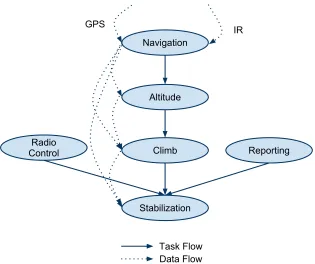
The basic design of the shared memory version of Paparazzi uses several shared objects ac-cessed various tasks to calculate vectors to control the UAV. This information consists of a navigator, estimator, and a flight plan. The following paragraphs will briefly cover each task and how it operates on these shared data structures in order to illustrate later how to redesign for a message-passing framework. The basic task layout for the auto pilot module with task dependencies and data flow are shown in Figure 2.6. Navigation Task: The navigation task is responsible for taking information from the GPS device, determining the current location of the UAV and then storing the values into the estimator data structure for later tasks that cannot read the GPS data. It then compares this information against the flight plan and determines target metrics for the UAV to meet the flight plan. Altitude Control Task: The altitude control task is responsible for determining the control values to reach/maintain the desired UAV altitude. It first ensures that the system mode is set to allow autopilot control. It then obtains data from the estimator’s z coordinates and determines the error from the desired altitude. It then uses this error factor to determine any corrections and commits them to one of the shared memory objects. Climb Control Task: The climb control task is responsible for determining the system’s output in terms of thrust and pitch in order to maintain the necessary altitude. It takes as input the altitude determined in the altitude control task and the z directional speed vector determined in the navigation task. It uses these inputs to calculate the necessary pitch and thrust to control the altitude of the UAV’s vertical changes. Stabilization Control Task: The stabilization control task uses data from the infrared (IR) device, the climb control task, and the navigation task. This task is responsible for determining the roll and any changes to the pitch. The stabilization control task in this implementation is also responsible for transferring the data to the FBW task that updates the actuation on the servos. The data sent is the pitch, roll, throttle, and gain to control the servos. Radio Control Task: This task takes the last radio control command from the FBW module and stores the data in the autopilot in case it needs to take over control.
2.3.2 Fly-By-Wire Base Design
'DWD)ORZ 1DYLJDWLRQ
$OWLWXGH
&OLPE
6WDELOL]DWLRQ 5DGLR
&RQWURO 5HSRUWLQJ
7DVN)ORZ *36
,5
Figure 2.6: Auto Pilot Task and Data Flow
pilot or the PPM device is controlling the UAV. It validates several device-based metrics to determine if the device is still receiving signals from the PPM device or if a fail-safe mode has been activated. Check Auto Pilot: This task controls the servos based on data received from the AP. The task receives data from the stabilization control task over the systems specified bus and then transfers these control values to the servos for actuation. Flight Model and Simulated Devices: In order to function appropriately Paparazzi requires a GPS device, IR device, and a functional flight model. The Flight model specifies flight dynamics based on the rudimentary version found in the Paparazzi open source code. The GPS device infers several metrics based on its current position, its last position and the change in time. The IR simulates a dual axis differential IR device, that uses IR temperature readings between space and the earth to stabilize the roll and pitch of the aircraft. The output data from the IR device is critical in the stabilization task.
2.4
Forte Implementation
'DWD)ORZ
&KHFN
)DLOVDIH
&KHFN$3
3307DVN
7UDQVIHU7R
$3
7DVN)ORZ
6LP)OLJKW0RGHOFigure 2.7: Fly-By-Wire Task and Data Flow
2.4.1 Input and Output Tasks
Implementing Paparazzi using the Forte design required analyzing the shared memory accesses that occurred within the task set and expressing them as data-flow relationships between tasks. The original implementation of Paparazzi uses logical objects to store data in containers. This eased programming requirements in that it made the data logically organized. However, it also made all data in these objects globally accessible. While this is suitable for single-core implementations, using shared data in multi-core scenarios adds overhead. We remedied this by transforming data flow relationships to remove shared object containers altogether. They were replaced by data designated in two ways.
First, we utilize local data when data is only operated on within a task. The majority of data in our implementation could be categorized as local data. This contains all temporary variables and most of the state variables that update the primary flight metrics during operation.
Second, we utilize remote data. This data is stored locally but the actual data values originated else-where and are communicated between cores via sends and receives. Remote data values are written to local memory of the task before the task is released. In Figure 2.6, the dotted lines represent the flow of remote data in the auto pilot module.
2.4.2 Scheduler
In the introduction of this paper, we made the claim that massive multi-core architectures could ease the problem of task scheduling. Trends in the market indicate that in the near future architectures with tens if not hundreds of cores will be arriving. In the past, processing resources were in heavy contention and sophisticated scheduling techniques were needed to arbitrate access to limited resources. The term limited can no longer be used to describe processing resources for massive multi-core architectures. For the Forte implementation of Paparazzi, the scheduler is a simple periodic scheduler. The scheduler statically deploys each task to its own core where it remains stationary. Taking advantage of the massive multi-core architecture, no tasks shared a core. Scheduling thus reduces to core activation/deactivation to release or terminate a task. Each task would then be set to sleep until it received a NoC-based message from the scheduler core waking it up to perform its task. The impact of the sleep state is significant in terms of power consumption. As the number of cores on these architectures scales up, that ability to power them simultaneously will become a serious challenge. In order to limit the scope of the power consumption of such chips, many chip designers are implementing low power sleep modes with instant-on functionality. This enables software to constantly turn offand on the resources needed while conserving power.
2.4.3 Fault Models
To simplify our experimental implementation, we integrated an n-modular redundancy configu-ration using the Forte model instead of a Simplex implementation. In our evaluation, we use a triple modular redundancy. This shows the flexibility of the architecture in that can use Forte’s design for three completely simultaneous instances of Paparazzi. This enables coherence checks to identify the faulty model in times of failure so that voting can occur to determine which model controls the simulated servos.
2.4.4 Coherence Checks
the faulting model from controlling the system servos. When a timeout occurs coherence is checked between the models that did submit data, any models that did not submit data are considered to have failed.
2.4.5 Rejuvenation
Rejuvenation is implemented in Forte in two ways. The feedback control algorithms support natural convergence and, as such, just require a restart mechanism and a warm up phase to re-enable coherence validation. Paparazzi utilizes such natural convergence, i.e., our imple-mentation exploits this restart capability. In addition, rejuvenation with refreshed data was realized as an optional extension. This allow us to compare the time (overhead) for convergence with and without refresh. To facilitate rejuvenation under data refresh, the coherence module uses the message passing network to indicate the source data refresh, i.e., one of the remain-ing correct tasks (cores). Refresh data is transmitted durremain-ing the next idle phase to ensure non-interference with real-time deadlines of the correct tasks. The refresh data is also received during the idle phase of the restarted task as redundant tasks are harmonic (not only in period but also in idle phase). Received data subsequently refreshes uninitialized state in tasks, either to ensure that outputs are within coherence thresholds or, as in the Paparazzi example, to speed up convergence amongst the redundant tasks.
2.5
Experimental Framework
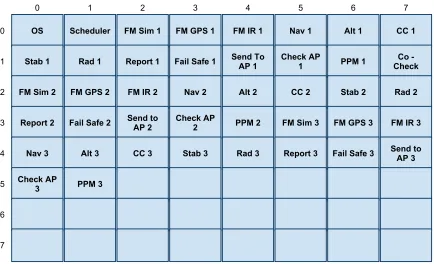
arbitrate access to the NoC using TDMA as described in previous sections. This reduces the impact of NoC effects on the system.
26 6FKHGXOHU )06LP )0*36 )0,5 1DY $OW &&
6WDE 5DG 5HSRUW )DLO6DIH 6HQG7R$3 &KHFN$3 330 &KHFN&R
)06LP )0*36 )0,5 1DY $OW && 6WDE 5DG
5HSRUW )DLO6DIH 6HQGWR$3 &KHFN$3 330 )06LP )0*36 )0,5
1DY $OW && 6WDE 5DG 5HSRUW )DLO6DIH 6HQGWR $3 &KHFN$3
330
Figure 2.8: Paparazzi Task Layout
We conducted experiments with both the message-passing and shared-memory approaches using triple concurrent redundancy to evaluate the effectiveness of the Forte framework. We employed targeted fault injection in each of the models by generating data errors to evaluate the effectiveness of the coherency checks. We injected faults into both code segments and actively used data segments. Faults were dynamically inserted into the code and configured to be trigger randomly during the execution of the control system through the flight path. To model full redundancy, we duplicated the simulated UAV hardware so that each model operated on unique device inputs.
2.6
Experimental Results
single coherence check to validate system data prior to servo actuation. The coherence check assessed the output data that was passed over the peripheral bus to the servo controller. We only included outcomes from SEUs that created an actual effect on the output state of the running systems. Faults were categorized as follows: (1) Downstream data errors: prior to servo actuation, outputs of the models were compared for consistency. By using three duplicated models, the faulting model is defeated (voted out). (2) Read-only (RO) memory upsets caused one of the models to fault. When this occurred, one model failed the coherence check through a timeout mechanism set by the coherence check’s data deadline.
Table 2.1: Fault Injection Evaluation
SEU Type Detectable SEU Count Recognized
Heap Flip 15 15
Device Failure 3 3
Stack Flip 10 10
Read Only Flip 4 4
The next experiment exemplifies one of the major benefits of the message passing design over shared memory. Figure 2.9 depicts the computational cost (in cycles) for accesses to data subject to coherency checks for both models. These results measure the coherence within the climb control model that maintains computational control over five of the system control variables. This coherency check validates the consistency of the three simultaneous climb control data sets. As Figure 2.9 indicates, shared memory results in an order of magnitude performance penalty compared to message-passing. The overhead of the latter is due to maintaining coherency for remote writes for the validation checks. The message-passing model eliminates the need for coherence and reduces conflicts on the interconnects resulting in more predictable and lower execution time.
Figure 2.10 depicts the overheads for computing integer data in the climb control task. These results show stable timings for task computation with message passing, much in contrast to shared memory. We evaluated integer computations because of a lack of hardware floating point units (FPU) on the Tilepro64. This data demonstrates how easily contention on the NoC results in jitter. In this result, three simultaneous models are executing while the previous results utilized only one active tile during the actual check. Note that when multiple tiles are active simultaneous jitter is easily introduced into shared memory accesses. In contrast, TDMA arbitrates NoC access for messages.
Figure 2.9: Overhead of Coherence: Shared Memory vs. Message Passing
Table 2.2: Rejuvenation: Time to Full Restart
SEU Scheme Time To Repair Mean Time to Failure
No Rejuvenation ∞ 157 Days
Natural Convergence 8 (2s) 2.27x10⁸ Days
Data Driven 1 (250ms) 2.05x10⁹ Days
triple redundancy is restored, i.e., voting within the system can restart. Table 2.2 depicts this as the time to repair for each scheme. Column two indicates that natural convergence took eight job cycles (periods) before voting could restart while rejuvenation with data refresh was able to accurately measure coherence one job (period) after the original failure. Column three assesses the mean time to failure (MTTF) for each scheme. Without rejuvenation, the model to derive data for the second row follows the standard MTTF calculation M T T FT M R = 5/(6λ). The model with repair via rejuvenation used to derive results for the third and fourth rows is based on a modified Markov formulation that calculates MTTF asM T T FT M R−Repair = 5/(6λ)+µ/(6λ2) [63]. µis the maximum number of repairs that can be performed within an hour. We evaluated our model based on the λ= 2.2083x10⁻⁴
Figure 2.10: Climb Control Task Jitter: Shared Memory vs. Message Passing
results, rejuvenation increases reliable operation by six to seven orders of magnitude.
of 1.8% is even observed in the message passing results when L3/hashing is active as a result of the forced address resolution and non-local data placement associate with hashing. Message passing under deactivated virtual L3/hashing results in lower jitter(only .5%).
Figure 2.11: Bulk Transfer Overhead: Shared Memory vs. Message Passing
Figure 2.12: Bulk Transfer Jitter: Shared Memory vs. Message Passing
Overall, the results indicate superior performance, increased predictability and reduced jitter of pure message passing (without any background coherence protocol) in this massive multi-core platform with a mesh-based NoC. Performance and predictability benefits of message passing over shared memory improve as the number of utilized cores increases, i.e, message passing scales in contrast to shared memory programming. The cause of these benefits lie in the potential of one-sided communication and TDMA arbitration of message passing in a push-based (explicit) access model. These advantages cannot be matched shared memory protocols with its pull-based (implicit) on-demand access requests and its required hand-shake semantics of the coherence protocol.
2.7
Related Work
Figure 2.13: Scaling Contention: Shared Memory vs. Message Passing
due to NoC resource contention on a single processor die. Another exception is Tilera’s iMesh paper [74], which investigates higher-level software overheads of the iLib abstraction for buffered channel and high-level dynamic messaging vs. row channels. Our work provides more insight on jitter and clarifies the overhead of shared memory accesses vs. the benefits of a much lower level messaging layer, which exposes the true overheads at the lowest software layers.
solutions aim at a reduced cost of protection,i.e., cost in terms of extra die size, performance penalty and increased code size. Hybrid approaches have been proposed for selectively protect-ing hardware regions, for control-flow checkprotect-ing and for reduced instruction and data duplication in software [56]. Data representations, however, have been widely ignored. Radiation hardening is another common technique in fault protection for real-time systems [32, 68] with overheads in costs and speed. In contrast to our work, these solutions either promote hardware approaches or do not consider massive multi-cores (or even real-time systems).
Modular redundancy is a replication technique[42]. This work provides an easy to imple-ment and validate approach to ensuring fault tolerance. The technique has been used widely in research. [50] describes a heterogeneous NoC architecture to implement triple modular redun-dancy. This work focuses on a specialized architecture that supports multiple levels of hardware integrated fault detection. This work uses TDMA on a NoC to interconnect the various IP ele-ments in the architecture. Our work also utilizes a replicated task mapping but differs in that it is a pure software approach that enables comparisons of varying task complexity models with COTS applicability. More significantly, their study is based on hardware simulation, ours is an actual implementation on a hardware platform. Theirs covers a small number of cores, ours is for massive multi-cores with high core count, which creates novel challenges for harnessing NoC contention.
Rejuvenation [81, 31] is a technique originally introduced as a software restart technique to protect long-running software. Rejuvenation is often associated with rebooting. A major hurdle in software rejuvenation is data loss due to the rejuvenation. Forte uses software rejuve-nation to maintain reliability in the control system. Data loss is circumvented through selective rejuvenation and data refreshing from validated data models.
2.8
Conclusion
Chapter 3
Low Contention Mapping of
Real-Time Tasks onto a TilePro 64
Core Processor
3.1
Introduction
Distributed software models on network-on-chip (NoC) processor architectures provide signifi-cant advancements but also challenges for real-time systems. These advancements come from simplifications in processor cores that result in increased accuracy of static timing analysis, simplified scheduling algorithms due to an abundance of cores, and synchronization free data resource models implemented through explicit inter-process communication (IPC) in the form of messages. Due to these advancements, this processor architecture is seeing increased use in hard real-time systems such as in [70] where the authors explore real-time hazard detection in satellites using the Opera Maestro processor [15], a radiation hardened TilePro with 49 cores developed by Boeing. A drawback of these processors is posed by NoC contention of multiple tasks. Such contention exists for shared-memory accesses, for off-chip memory references and for message passing when utilizing distributed software models instead of shared memory. Our work focuses on message passing over the NoC assuming separate NoC interconnects for mem-ory, coherence, I/O and messaging [6]. Other work on increasing predictability and coping with non-uniform memory latencies is orthogonal [46].
Figure 3.1: NoC Contention (Config 1)
NoC with full-duplex links, i.e., two messages traveling in opposite directions over a link do not result in contention, that utilizes static dimension-ordered wormhole routing favoring hor-izontal routing before vertical [6]. Consider the example “Config 1” in Figure 3.1 of nine cores with a mesh NoC. Two messages are sent, one from core 4→ 2 and the other from 3→ 8, as depicted by the lines with arrows. When sent at the same time, contention on the link 4→ 5 (depicted as a thick link in the NoC mesh) results in a delay for one of these messages due to arbitration within the NoC hardware routers. (Packets are not interleaved as an open virtual channel monopolize links between endpoints.) As a result, sending tasks experience highly variable latencies. Such variability can be reduced or even eliminated when tasks are layed out intelligently to lower or even completely avoid contention, respectively. The effect shown in this example is amplified as the size of NoC meshes increases resulting in larger paths through networks and communication that is more frequent.
within hours.
To the best of our knowledge, this is the first work to address predictability of NoC commu-nication via framing messages into temporal windows for real-time tasks. Previous work [16] viewed communication as temporally stateless. This limited the amount of communication that could feasibly be solved. It also resulted in solutions that were overly conservative in thatany potentialfor common message routes were considered contention. By using temporal windows, we are able to solve the problem by separating temporally disjoint messages when analyzing link contention scenarios and thus increasing communication predictability.
3.2
Software-Based Temporal Framing
Temporal framing is a technique similar to time-division multiple-access (TDMA) that imposes frames to bound communication into time windows. It differs from TDMA in that it does not limit the amount of IPC in a single frame; instead, it is used solely for analysis purposes to try and statically map tasks to processors and to reduce communication interference. Programmat-ically, this is facilitated using self-referential frame checking within a task for identifying when a specific message can be sent/received. To guarantee predictability within a real-time environ-ment, we assume that senders and receivers are at least predetermined within the hyper-period of a periodic task set and that communicating pairs are guaranteed to be active during any frame in which they send or receive data. This assumption is easily supported under the dark silicon model because high utilization and delays due to resource sharing do not exist. Because of this assumption, we can then use temporal frames as a means of synchronizing senders and receivers to reduce latency incurred through non-synchronized IPC.
As an example consider the nine real-time tasks shown in Figure 3.2 where tasks are rep-resented by shaded blocks. In this figure, the execution of the system is broken into twelve temporal frames. Communication in a frame is represented by indicating within a sender’s frame the receiver address. Communication too large to fit within a single frame is considered across multiple frames. For example, Task 3 send a message to Task 8 during frames nine and ten (see Figure 3.2). Using this model, we formulate a mathematical model to map tasks to cores while maintaining temporarily disjoint communication.
Figure 3.2: Temporal Framing Example
to task 8 in frame 2 of Figure 3.2, sends from tasks 3 and 6 would result in input contention at task 8, the receiver of both. Whichever send, that of task 3 or 6, comes later, it would block until the earlier message has been received due to input contention. In the following, we will explicitly refer to “input contention” and otherwise use the term contention to refer to “link contention” within the mesh.
3.3
Motivation
Let us provide a motivational example to assess the impact of contention-based latency on real-time tasks. We use a 3x3 NoC with nine tasks broken into 12 temporal frames as described in the previous section, our “running example” used throughout the paper. The randomly generated task set has high utilization that takes advantage of the NoC architecture using message-based IPC. There are 10 messages that are sent within the hyper-period. These messages are shown in the temporal framing example in Figure 3.2. We evaluated three layouts of the tasks on the NoC, each with different amounts of network contention, to show the impact of contention on jitter.
Figure 3.3: Contended Network Resource (Config 2)
The na¨ıve layout results in contention along edge 4 → 5. This contention is a result of two simultaneous messages, as previously described. There is actually an additional message during this frame 9 from Tasks 5→ 1 (see Figure 3.2) that does not result in contention due to link duplexing.
The second contention scenario, “Config 2” in Figure 3.3, contains a shows the effect of contention across multiple temporal frames and its effect on jitter. Temporal frames 7 and 9 result in contended links between two sending/receiving pairs in each frame.
We also evaluate a third layout without contention, “Optimal” in Figure 3.4. No routes are shown in this figure due to the absence of contention since links are full duplex, i.e., edge traversals initiated on opposite ends of a link do not result in contention.
Figure 3.4: Zero Cost Network Layout (Optimal)
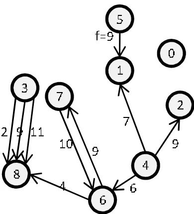
Figure 3.6: Temporal Framing Graph
3.4
Exhaustive Solver Model
We utilize the temporal framing model described previously as a basis for a constraint pro-gramming formulation. This reduces contention, ease analysis, and maintain communication flexibility. The constraint framework allows us to systematically determine optimal task-to-core mappings for NoC architectures. In the formalization, the set of tasks is considered as a temporal frame graph shown in Figure 3.6. The figure depicts the graph representation of our running example representing any inter-task communication, and edge weights indicate the time frame during which the communication occurs. We construct temporal frame graphs based on the specification of communication within the real-time task sets (as in Figure 3.2) and map them onto a core graph, a representation of the NoC topology. We then formulate a constraint-programming model that is solved in a branch-and-bound traversal to enumerate and evaluate all possible mappings so that the amount of IPC based contention is minimized. The following definitions specify the constraint model for determining an optimal solution (there may be more than one) that minimizes contention.
Definition 2: A Directed Mesh Graph G= (V, E) is a representation of cores over a NoC wherevi ∈V represents cores on a NoC andei ∈E is an edge between two coresvi, vj identified in directional order by (vi, vj).
Definition 3: A function M ap(t) maps vertext∈T onto a vertexv∈V.
Definition 4: An ordered setP ath(vi, vj) denotes the XY dimension ordered edges on the Manhattan path [40] (edge traversal) betweenvi, vj ∈G.
Definition 5: A function Cross(vi, vj, vm, vn) is defined as
Cross(vi, vj, vm, vn) =
|P ath(vi, vj) if vi(=vj∧
∩P ath(vm, vn)| vm(=vn∧
|P ath(vi, vj)∩ P ath(vm, vn)|>0
0 Otherwise
.
Definition 6: Function Cost(c1
, c2
) withc1
, c2∈
C is defined as
Cost(c1, c2) =
Cross(M ap(t1
i), M ap(t1j), M ap(t2
i), M ap(t2j)) if c1f (=c2f
0 Otherwise
.
Definition 7: The objective function (to be minimized) is M in(T F G) = %
c1∈C,c2∈C Cost(c1
, c2
).
Definition 8: A set of constraints on the minimization function are defined as ∀t1 ∈
T,∀t2 ∈T :t1(=t2 =⇒ M ap(t1)(=M ap(t2).
full duplex edges that exist in many NoC architectures. To determine the conflicts that occur between two paths, we define the functionCross(vi, vj, vm, vn) that specifies the cardinality of the intersection of the two paths defined by (vivj) and (vm,vn).
The Cross function is used to define a scalar function Cost(c1
, c2
) parameterized by two edges obtained the TFG graph (see Def. 6). It then applies the map function on source and destinations inc1, c2 and determines the number of contended links that exist between the two
paths. This determines the total number of contended links that exist on the paths defined by c1
and c2
assuming that c1
and c2
occur during the same temporal frame. Otherwise, the result is zero since communication does not exist during the same temporal frame and thus no messages can interfere with one another. The optimization function of this constraint framework is minimizing the sum of the cost functions across all edges in the TFG. The constraints to bound this function enforce a unique mapping,i.e. each task is mapped to one core and no two tasks share a core (see Def. 8).
3.5
Heuristic Model
Branch and bound, exhaustive optimization solvers scale exponentially as the number of vari-ables grow. This holds true in our exhaustive contention solver detailed in the previous section. Solutions for NoCs 5x5 and larger can take hours to obtain an optimal solution. This is partic-ularly true when the full depth of the search tree has to be traversed, even when optimized in C and parallelized over multiple nodes (using MPI) as in our implementation. We developed HSolver, a heuristic solver to create a low contention layout for NoCs too large to be solved exhaustively. HSolver is a multi-heuristic solver designed based on patterns identified from optimal solutions generated from the exhaustive solver.