United States Patent [19]
Rudi et al.
[54] MAGNETIC TAPE RECORDER
Guttorm Rudi, Fjellhamar; Jan-Erik Dilling, Oslo, both of Norway
[73] Assignee: Tandberg Data A/
S, Oslo, Norway
[21] Appl. No.: 587,579
[22] Filed: Mar. 8, 1984
[30]
Foreign Application Priority Data
[75] Inventors:
4,636,890
Jan. 13, 1987
[11]
Patent Number:
[45]
Date of Patent:
4,559,571 12/1985 Olmsted et al. ... .. 360/105 4,573,091 2/l986 Barton et al. ... .. 360/96.5
Primary Examiner—Robert S. Tupper
Attorney, Agent, or Firm-Hill, Van Santen, Steadman &
Simpson
[57]
ABSTRACT
In an exemplary embodiment a cassette provided with
the magnetic tape is inserted in a longitudinal direction into an insertion channel. During and/or after the inser
May 16’ 1983 [DE] Fed‘ Rep‘ of Germany """ " 3317720 tion of the cassette, a magnetic head carrier provided [51] Int. Cl.4 ... .. G11B 5/54; G11B 21/12 with a magnetic head is pivoted from an idle position [52] US. Cl. ... .. 360/96.5; 360/105 into an operating position in which the magnetic head [58] Field of Search ... .. 360/ 105, 96.5 contacts the magnetic tape. The pivotal movement is
[56] References Cited effected by a lever linked to the magnetic head carrier. The lever is actuated by a connecting rod which is
US PATENT DOCUMENTS linked to a cover for closing the insertion channel. The
3,959,821 5/1976 Nardino ... .. 360/105 movement of the lever by the connecting rod ensues via
3,976,262 8/1976 Kennedy 360/96.4 a rotatably mounted swivel arm. When the cover for
3,937,436 10/1976 119 e1 111- - 360/965 the insertion channel is opened, the magnetic head is
,llE‘gh‘k ' ' ' ' ' ' ' ‘ ' " pivoted back into its idle position and the cassette is
4:344:09.’ 8/1982 T3;
“0/966
simultaneously partially ejected from the magnetic tape
4,396,963 8/1983 Wright 360/105 recorder byt e Swivel arm4,491,889 l/l985 Tsuchiya . . . . . . .. 360/105
4,498,112 2/1985 Georgens et al. ... .. 360/96.5 13 Claims, 2 Drawing Figures
29 31]
2e 2 21 21.
\l
‘ o, 19
// _
// A
T 22
j/ ' ‘Eel’ / 1g
25”!’
’ l ,7”
17 ‘
III’
\ l‘
1
\1
\l
I \\\ / I
I \\§ / I-B
III
\\ §\
4/ pg
III
5 \
“15
I,’
_\\\
°P
1f
1,21 20 {Q1 7
40
II.) I I '\
lip/C‘T" ‘"~ 3! ° -l5
3’FL-_-_-_-I I=“=-::_=i._t=:-_;k*=
FT
1
,I/
21'
.
3- 5
I.“ =1 .
US. Patent Jan. 13,1987
Sheetl of2
4,636,890
US. Patent Jan. 13,1987
Sheet2of2
4,636,890
FIG 2
2
293029
I
2!.
4,636,890
1
MAGNETIC TAPE RECORDER
CROSS-REFERENCE TO RELATED APPLICATION
Reference is made to a prior ?led pending application for patent in the name of Guttorm Rudi, U.S. Ser. No.
555,151 ?led Nov. 25, 1983, entitled “MAGNETIC
TAPE RECORDER”, and which corresponds to Ger man Patent Application P No. 32 44 165.7, ?led Nov.
29, 1982.
BACKGROUND OF THE INVENTION
The invention relates to a magnetic tape recorder wherein a cassette for the storage of data signals can be
placed into operative association with a magnetic head which is capable of data recording and/or playback operation. The magnetic tape contained in the cassette
can be moved past the magnetic head with the use of a
capstan drive energized by a tape drive motor.
Magnetic tape recorders are already generally known
wherein data are recorded on a magnetic tape contained
in the cassette and are read from said magnetic tape.
When recording digital data, a cassette is employed
which contains a capstan idler and a pivotably disposed dust cover in addition to the reels for the magnetic tape. The cassette is usually inserted transversely into an insertion channel of the magnetic tape recorder. The dust cover is thereby automatically opened. For the
purpose of driving the magnetic tape, a tape capstan
presses said tape against the capstan idler. Further, a magnetic head contacts the magnetic tape at the area exposed by the dust cover in order to record or read the
data. '
A magnetic tape recorder is disclosed in the earlier German patent application P No. 32 44 165.7 corre sponding to US. Ser. No. 555,151 wherein the cassette is inserted in a longitudinal direction. The drive capstan driven by the tape drive motor and a magnetic head are
disposed at one side of the insertion channel. While the
cassette is being inserted, the dust cover at the cassette
is hinged out by means of a pivot arrangement as the cover covering the insertion channel is closed, to ex
pose a tape scanning location. The magnetic head is disposed on a magnetic head carrier pivotable about an
axis, said magnetic head carrier pivoting to shift the magnetic head into the scanning location in place of the
dust cover after it has been opened, for scanning of the magnetic tape. After the cover for the insertion channel is closed, the cassette is locked in a de?ned work posi tion. When the cassette is being removed, the magnetic head is pivoted back out of its operating position into an idle position after the cover for the insertion channel
has been opened. Subsequently, the dust cover is hinged
back into the cassette. In this earlier magnetic tape re
corder, the pivoting of the magnetic head carrier and
the ejection of the cassette are effected with the use of
springs. -
SUMMARY OF THE INVENTION
The object of the invention is to improve such a magnetic tape recorder to the effect that the sequences
upon insertion and upon removal of the cassette are
precisely de?ned and, in particular, the movement of
the magnetic head carrier is precisely de?nable. Given the magnetic tape recorder of the type initially
de?ned, the object is resolved by providing a connect
ing means, one end of which is connected to an insertion
7-1 0
20
45
65
2
means in the form of a cover for the insertion channel, and the other end of which is connected to a swivel
means. The swivel means also connects to a lever which
in turn connects to the pivotable magnetic head. As the
cover is closed, means are actuated for opening the dust
cover and simultaneously the magnetic head is swung
from an idle position behind the dust cover into an
operating position. The swivel means also preferably
serves as a stop during initial insertion of the cassette
prior to closing the cover and placing the cassette in its
?nal operating position. Additionally, during opening
of the cover, the swivel means causes the cassette to
reject. ,
The magnetic tape recorder according to the inven tion has the advantage that a precise de?nition of the motion sequences is possible with low outlay and that a re-adjustment is not necessary.
The magnetic tape recorder exhibits high protection
against malfunction. For example, it is not possible to place the cassette into its operating position when the
cover is open due to a self-blocking position of a swivel
arm.
An exemplary embodiment of the inventive tape re corder is explained in greater detail below with refer ence to the accompanying drawing sheets; and other
objects, features and advantages will be apparent from
this detailed disclosure and from the appended claims.
BRIEF DESCRIPTION OF THE DRAWINGS
FIG. 1 is a diagrammatic plan view of the magnetic
tape recorder given an open cover; and
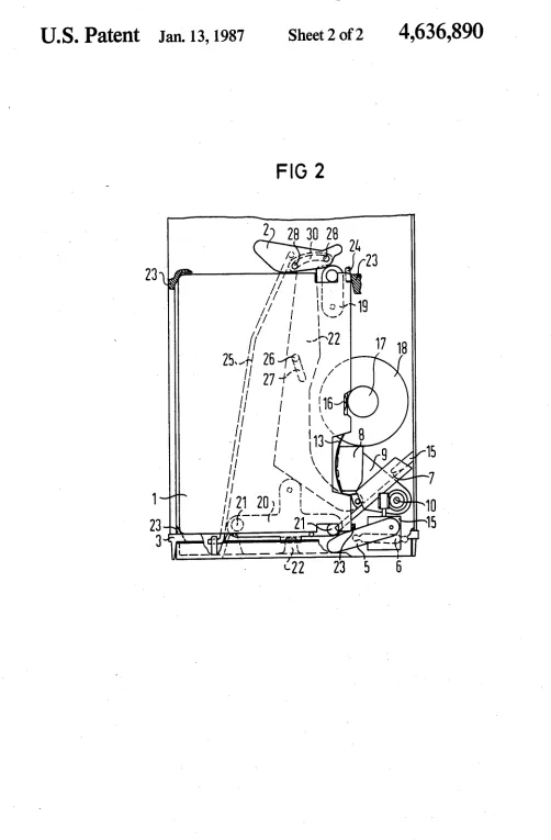
FIG. 2 is a diagrammatic plan view of the magnetic
tape recorder given a closed cover.
DETAILED DESCRIPTION
The magnetic tape recorder or magnetic tape trans
ducer system illustrated in FIG. 1 exhibits an insertion channel for receiving a cassette 1. The cassette is shown
in a partially inserted position. The cassette 1 is inserted into the insertion channel in a longitudinal direction and
is held in the partially inserted position shown in FIG.
1 by means of a swivel arm 2 that is situated in a self
blocking position at the back end of the insertion chan nel. The housing 3 of the magnetic tape transducer unit
is provided with a pivotable cover 4 that is shown in its
open position in FIG. 1. The magnetic tape transducer unit contains a pivot arrangement formed of the swivel
arm 5 and a connecting rod 6, said pivot arrangement
serving the purpose of automatically opening the dust
cover 7 of the cassette 1. The swivel arm 5 is rotatably mounted for movement about an axis 5a. One end of the
connecting rod 6 is coupled with said swivel arm 5 and
its other end is disposed at the inside of the cover 4. A
magnetic head 8 is secured to a magnetic head carrier 9
that is pivotable about a shaft 10. Given an open cover
4, the magnetic head 8 is situated in the illustrated idle position. It was brought into this position by a lever 22 while the cover 4 was being opened, said lever 22 being
connected to the cover 4 via the swivel arm 2 and a
connecting rod 25. The lever 22 is rotatable around a
pin 26 disposed at the lower side of the magnetic tape
transducer unit and is also displaceably mounted as a consequence of the oblong hole 27 in lever 22. The swivel arm 2 is rotatable about a pin 28 and the traction mechanism 25 acts upon it. The swivel arm 2 also con
4,636,890
3
Further details are described below with reference to
the plan view illustrated in FIG. 2.
When the cover 4 is closed, the free end of the swivel arm 5 presses against a lever like extension 7a of the dust cover 7 and hinges said dust cover 7 away from the cassette. Further, the tie rod 25 turns the swivel arm 2
about the pin 28 (clockwise as viewed in FIG. 2) while
the cassette 1 is simultaneously being inserted into the magnetic tape transducer unit. With the rotation of the
swivel arm 2, the lever 22 is also turned (clockwise as viewed in FIG. 2) around the pin 26 and is simulta
neously displaced to the extend permitted by the open
ing 27. Since the magnetic head carrier 9 is coupled to
the other end of the lever 22 as indicated at 9a, said
carrier 9 is pivoted by the motion of the lever 22 from
its idle position into the operating position illustrated in
FIG. 2. The lever 22 is thereby pressed against a stop by
the connecting rod 25, whereby the connecting rod 25
is deformed such that it acts like a spring in order to
press the lever 22 against the said stop.
The magnetic head 8 is displaceable by a driver motor 15 in the direction of the shaft 10 and, thus per
pendicular to the running direction of the magnetic tape
13 in order to be able to position the magnetic head 8 in scanning relation to different tracks of the magnetic tape 13. The dust cover 7 is held in its open position by
a detent 15'. Said detent 15’ can also serve as a detent for
the magnetic head carrier 9 in its idle position.
A capstan idler 16 is disposed inwardly offset at a
recess 1a in the cassette 1. The capstan 17 and the tape
. drive motor 18 are therefore pivotably designed so that
the capstan 17 rolls along the long side of the cassette 1
as illustrated in FIG. 1 when the cassette 1 is inserted or
withdrawn. The tape drive motor 18 is expediently
mounted for pivotal movement on an axis indicated at
18a intersecting its center of gravity, the tape drive
' motor 18 and capstan 17 being resiliently biased toward
' the cassette 1.
In the ?nal position of the cassette 1, leaf springs 19
if and 20 provided with balls 21 press from below against
said cassette 1. The leaf spring 19 presses against the
cassette 1 with a predetermined pressure whereas the
leaf spring 20 presses against the cassette 1 with a lower pressure. When the cover 4 has been completely closed,
a wedge 200 on the cover 4 presses against the leaf
spring 20 so that this leaf spring presses toward the
cassette 1 with the same pressure as the leaf spring 19.
The balls 21 thereby engage in corresponding recesses
of the cassette 1. Corresponding surfaces 23 are pro vided at locations of the insertion channel allocated to the four corners of the cassette 1 for the purpose of
locking the cassette in the ?nal position. Further, refer ence pins 24 are provided for de?ning a plane of refer ence of the magnetic tape 13. One of said reference pins is disposed at the back end of the insertion channel whereas three reference pins are disposed at the inside
of the cover 4 and contact the cassette 1 when the cover
4 is closed.
As the cover 4 is being opened, the swivel arm 9 is
again turned under the influence of the tie rod 25 and the lever 22 displaces the magnetic head carrier 9 back
into its idle position. At the same time, the swivel arm 2
partially ejects the cassette 1 from the magnetic tape
recorder, as shown in FIG. 1. The cassette 1 can be
removed from the magnetic tape recorder in this posi
tion. An insertion of the cassette 1 into its work position is not possible, due to the self-blocking position of the
0 20 45 60 65
4
swivel arm 2. In order to insert said cassette, the cover
4 must ?rst be closed again.
It will be apparent that many modi?cations and varia tions may be made without departing from the scope of the teachings and concepts of the present invention.
We claim as our invention:
1. A magnetic tape transducer system for use with a cassette containing a tape and having a drive opening
and a tape scanning location protected by a pivotable
dust cover at a front end, and ?rst and second lateral
ends substantially perpendicular to the front end, com
prising:
an insertion channel means for receiving the cassette
?rst lateral end leading, the insertion channel
means having a back end adjacent the inserted ?rst lateral end when the cassette is fully inserted and a
front side parallel to an insertion direction of the cassette;
a drive means positioned at said front side of the insertion channel means for interaction with the
cassette drive opening;
a magnetic head also at said front side and positioned to interact with the scanning location of the cas
sette;
manually activatable cassette insertion means for
inserting a partially inserted cassette into a ?nal position in the insertion channel means;
means coupled to the insertion means for pivoting the
pivotable cassette dust cover from a closed position to an open position as the cassette is inserted into
the insertion channel means;
a connecting means having a ?rst end connected to the insertion means and an opposite end connected
to a swivel means;
a lever means connected to the swivel means;
pivotable magnetic head carrier means mounting the
magnetic head and being connected to the lever
means; and
said connecting means, swivel means, and lever means together forming means for simultaneously
pivoting the magnetic head into operative position
simultaneously as the insertion means is insertingthe cassette into its ?nal position and the dust cover
is pivoting open, the magnetic head pivoting into
the operative position behind the dust cover with precise de?nitional movement.
2. A system according to claim 1 wherein said lever
means has one end connected to the swivel means and
the other end connected to the magnetic head carrier means, and wherein means are provided allowing pivot ing and displacement motion of the lever means when
acted upon by the swivel means.
3. A system according to claim 1 wherein said swivel
means, prior to manual activation of the insertion means to insert the cassette prevents insertion of the cassette
into its ?nal position by blocking further insertion of the
cassette into the insertion channel means, and when
ejecting a cassette by operating the manual insertion
means, said swivel means partially ejecting the cassette
from its ?nal position in the insertion channel means.
4. A system according to claim 1 wherein the con
necting means comprises a connecting rod having one
end connected to the insertion means, the other end connected to the swivel means, and wherein the lever
means has one end connected to the swivel means and
the other end connected to the magnetic head carrier
4,636,890
5
5. A system according to claim 1 wherein the inser
tion means comprises a cover which covers at least a
portion of an entrance to the insertion channel means. 6. A system according to claim 5 wherein the means for pivoting the dust cover comprises a swivel arm means for pivoting as the cover is closed, said swivel
arem means abutting against a portion of the dust cover
to pivot it open.
7. A system according to claim 1 wherein the lever
means has a substantially central oblong-shaped hole and wherein a pivoting means rides in said hole so as to
allow both displaceable and pivotable motion of the
lever means.
8. A system according to claim 1 wherein the lever
means has an oblong opening at one end which receives a pin mounted on the swivel means, wherein an addi
tional oblong aperture is provided centrally of the lever
means which receives a pivoting pin, and wherein the
magnetic head carrier means is connected at the oppo site end of the lever means.
9. A system according to claim 1 wherein a leaf spring means is provided adjacent an insertion end of the insertion channel means for pressing against the cassette in its ?nal position.
10. A system according to claim 1 wherein a leaf spring means is provided adjacent the back end of the insertion channel means for pressing against the cassette
in its ?nal position.
11. A system according to claim 1 wherein the means for pivoting the dust cover comprises a connecting rod
having one end connecting to the insertion means and the other end connecting to a swivel arm having one
end connecting to a rotational axis member and the
other end abutting a position of the dust cover. 12. A magnetic tape transducer system for use with a
cassette containing a tape and having a drive opening
and a tape scanning location protected by a pivotble
dust cover at a front end, and ?rst and second lateral
ends substantially perpendicular to the front end, com
prising:
an insertion channel means for receiving the cassette
?rst lateral end leading, the insertion channel
means having a back end adjacent the inserted ?rst lateral end when the cassette is fully inserted and a
front side parallel to an insertion direction of the cassette;
a drive means positioned at said front side of the
insertion channel means for interaction with the
cassette drive opening;
a magnetic head assembly also at said front side and
positioned to interact with the scanning location of
the cassette;
a manually activatable cover means for inserting a
partially inserted cassette into a ?nal position in the
insertion channel means when closed and for caus
ing an ejection of the cassette therefrom when
opened;
means coupled to the insertion means for pivoting the pivotable cassette dust cover from a closed position to an open position as the cassette is inserted into the insertion channel means;
20 25 35 45 65
6
a connecting means having a ?rst end connected to
the insertion means and an opposite end connecting
to a linking means; ‘
a lever means connected to the swivel means;
pivotable magnetic head carrier means mounting the magnetic head for pivoting in a horizontal plane
parallel with a tape running direction at the scan
ning location, the carrier means being connected to
the lever means; and
said connecting means, linking means, and lever means together forming means for simultaneously
pivoting the magnetic head into operative position
simultaneously as the insertion means is insertingthe cassette into its ?nal position and the dust cover
is pivoting open, the magnetic head pivoting into
the operative position behind the dust cover with
precise de?nitional movement.
13. A magnetic tape transducer system for use with a
cassette containing a tape and having a drive opening and a tape scanning location protected by a pivotable
dust cover at a front end, and ?rst and second lateral
ends substantially perpendicular to the front end, com
prising:
an insertion channel means for receiving the cassette
?rst lateral end leading, the insertion channel
means having a back end adjacent the inserted ?rst lateral end when the cassette is fully inserted and a
front side parallel to an insertion direction of the
cassette; '
a drive means positioned at said front side of the insertion channel means for interaction with the
cassette drive opening;
a magnetic head also at said front side and positioned to interact with the scanning location of the eas sette;
manually activatable cassette insertion means for
inserting a partially inserted cassette into a ?nal
position in the insertion channel means;
means coupled to the insertion means for pivoting the
pivotable cassette dust cover from a closed position
to an open position as the cassette is inserted into
the insertion channel means;
a connecting means having a ?rst end connected to the insertion means and an opposite end connected to a linking means;
a lever means connected to the linking means;
movable magnetic head carrier means mounting the magnetic head and being connected to the lever
means;
said linking means in a ?rst position prior to activa
tion of the insertion means for inserting the cassette
into its ?nal position, blocking further insertion of
the cassette into the insertion channel means; and said connecting means, swivel means, and lever
means together forming means for simultaneously
pivoting the magnetic head into operative position
simultaneously as the insertion means is insertingthe cassette into its ?nal position and the dust cover
is pivoting open, the magnetic head pivoting into
the operative position behind the dust cover with
precise de?nitional movement.