MODERN LARGE-SCALE COMPUTER SYSTEM DESIGN* by
'''alter Fo Bauer
The Ramo -'{ooldridge ·Corporation Los Angeles; California
June
8,
1956The objective of this report is to provide a survey of modern computer system design technology especially as it pertains to the use of large-scale
syst~ms for commercial and scientific purposes~ The areas to be discussed are: Memory Devices, Information Storage and Internal Checking, Operating Speeds, Instruction Logic, and Input-Output and Off-Line Equipmento The components or design aspects of a number of modern computer systems will be referred to including the IBM.:..701, IBM-704, IBM-705, NORC, BIZMAC, UNIVAC I, UNIVAC II, Univac Scient~fic Models 1103 and 1103A, and the LARCu These are the computers available for rent or purchase, or built by organizations which rent or sell computers 0 Occasionally other computers i4'i11 be referred to. Under System Design, the Project ERMA machine and the Office of Air Controller IP.achine 1vill be briefly discussedo In this survey and comparison, emphasis will be placed on the ~usual or especially commendable aspects of the systemo
Conspicuous by its absence here is a Bibliography of articles on the various machines and techniques presentedoln this most rapidly changing ~ield, most new developments are alniost never found in books, and are seldom found in journals 0 The information recorded here \Vas gained through reading
manufacturers I 'reports and brochures, through discussions with manufacturers'
agents, and through conversations with computer people generally. Manufacturers' reports, brochures,
ana
discussions are available for the asking 0Memory Devices
The first\operating stored.program computer, the SEAC computer of the National Bureau of Standards, 1-TaS equipped with mercury delay line memory 0 A
short time later the ERA-IIOI computer appeared with its magnetic drum memoryo Again within approximately one year's time, the first cathode ray tube storage machines appeared, the first one of which, and most notable, was the Whirlwind I computer at MoloT. The family of Institute for Advanced Study ~chines in-volved the Vlilliams tube-type storage whi.ch was somewhat different in design from that of the MoIoT .. storage tube design 0 More recently the trend is
toward the magnetic core memorYe The fi.rst ma~hines of conunercial availability which 1-Tere produced with· magnetic core memories\vere the Univac Scientific} Model 1103 computers, and the first one delivered went to the Operations Research Office of J'ohns Hopkins University in July, 1954Q All succeeding 1103 type computers and the 1103A types to follow have magnetic core memories. With the more modern computers} again commercially available, the IBM-702 had electrostatic storage as did the 7010 The 704 and 705 are equipped with. magnetic core memories ..' The UNIVAC I is the only computer ever produced commercially with a mercury· delay line type memory. Its successor, the UNIVAC II} to become available this year will involve a magnetic core memory for the basic high-spe~d internal storage deviceo
2
-Thus the significant trend in memory devices is toward magnetic core memory. Early electrostatic memories were of rather 'low reliability. They required frequent adjustments during normal operating periods, and frequently the machine designers found it desirable to re-design deflection circuitries and ,other 'associated equipment. The result was that after two or three years of
improvement gained through trial, error; and bitter experience, electrostatic storage ,became a reliable instrument and computers using this memory were very frequently recording reliability figures higher than
90%. '
However, the P9ten-tial reliability of the magnetic core type is considerably greater. In private correspondence with William Papian of M.I.T., . this writer received the following information in regards memory reliability of Whirlwind I after the replacement of:the electrostatic memory with ,the core: "The main interval between memory parity, alarms increased from a few hours to about two weeks, while the maximum interval went up from a few days to approximately six weekso Specific memory maintenance time was reduced from a large figure to a couple hours per month". Thus, the reliability measured in terms of intervals between parity alarms or as represented by maintenance time increased by a factor of at least 10 in this case. Since probably upwards of70%
of the down time caused by elec-tronic component failure (not including electro-mechanical devices) of acomputer can be attributed to memory device failures, 'overall computer reliabil-ity will jump considerably 0
Besides the advantages over electrostatic and mercury delay line type memories in areas of reliability, magnetic cores offer a tremendous speed advan-tage. The'average access time with the mercury delay lines in the SEAC computer is 192 mi'cr'os'econds 0 This can be compared with the 6 -10 microseconds access time with the core memories. Magnetic cores offer only a slight margin of greater speed over electrostatic types since electrostatic memories usually operate in the 10 or 12 microsecond region (some considerably higher), whereas magnetic cores operate in the 6-8 microsecond regiono Specifications and' characteristics of a number of modern computers are given in Table 1. The 4
microsecond ,memory cycle of the
LARC
computer as presented there is essentiallyan
effective cycle since the design is such that there is a 2 microsecond over-lap between the next operation and the last 2 microseco~ds of the normal6
microsecond cycle "time of the memory, -- that is) the normal.memory cycle in-volves something like the following: 2 microseconds for select and 2 micro-seconds for. the destructive reado Selection of the next read is performed simultaneously with re-writing the information destructed in the reading
operation. .
" It is generally agreed among computer designers that the conventional ferrite core cannot be switched at speeds which would result in basic cycles considerably less than
4
microsecondso Certain investigations continue in the direction of non-destructive read techniques. Also, it is expected that the future will show shorter memory accesses with a magnetic device called the"film wafer". In this technique, the resulting magnetic ,field is extremely low in power ,and consequently can be switched at extremely high rates. Signal amplification and reliability will be the critical obstacles in this development.
High Speed Storage* High Speed Storage Drum
Computer Memory Type Access Time Capacity Memory
IBM-701 Cathode Ray Tube
or Magnetic Core 12 2,048 or 4,096 8192 words
IBM-704 Magnetic Core 12 4,096, 8192 or 16,384
8,192 or words
32,768 words
IBM-702 Cathode Ray Tube 23 10,000 characters 60,000 characters
IBM-705 Magnetic Core 17 20,000 characters 60,000 characters
NORC Cathode Ray Tube 8 3,600 words
BIZMAC Magnetic Core 20 4,096 characters 16,368 or
32,736 characters
UNIVAC I Mercury Delay Line 400 (max.) 1,900 words
UNIVAC II . Magnetic Core 40 2,000-10,000
words
Univac Scientific Cathode Ray Tube or 12 1,024 words 16,384 'Words
Model 1103 Magnetic Core 8
Univac Scientific Magnetic Core 8 4,096, 8,192 or 16,384 words
Model 1103A 12,288 words
LARC Magnetic Core 4 20,000-97,500
words 3,000,000 words
*
in microsecondsCOMPUTER STORAGE
- 4 ..
Corporation has announced the future availability of a 32,000 word magnetic core storage. The three options available are 4,000, 8,000, and 32,000 words with respective monthly rental figures of approximately $6,000.00, $12,000.00 and $15,000.00. The difference in rental price between 8,000 words of core storage and 16,000 words of drum storage, as compared with 32,000 words core storage, is almost ne~ligible. Because of this, most installations who have need for 8,000 words of magnetic core and a considerable amount of drum storage are ordering the 32,000 word core storage. Presently,up to 12,000 words of magnetic core storage are available on the 1103A computer, together with 16,000 words of drum storage. It is expected that optional replacement of the magnetic drum with magnetic core will be announced soon.
Dr. Edward Teller of the University of California Radiation Laboratory at Livermore which wrote the specifications for and ordered the LARC computer, opined at the Western Joint Computer Conference in San Francisco in January, 1956, that the 50-100,000 words of high-speed storage to which people have occasionally referred, does not appear on the horizon as a necessity for the hydrodynamics applications of that group. Essentially, the Livermore group feels that the 20,000 words of core storage will suffice. The interest in the 32,000 words of core storage in connection with the IBM computers as referred to above largely results only from the fact that the small increase in price is attractive even in view of the increase, only moderate, in flex-ibility and convenience with the capacious high-speed storage. There is little doubt, however, that the future will see many problems requiring 32,000 word, or larger, core memories.
The need for a moderate-speed, medium access and high volume storage for commercial purposes is great, however. IBM has recently announced the IBM-305 Magnetic Disc memory. This memory will allow relatively low access to 5 million characters of information stored on discs to which reading and recording heads will travel for read and write operations. Remington Rand had included in their LARC proposal a magnetic disc file which would allow access to each of two million words of information in less than one second. This has been removed from the LARC equipment complement but a reasonable guess is that equipment of this type is contemplated for future systems.
On Table 1 there is also included the drum storage available on the various computers. The drums on the 701., 704, and 705 computers turn at
rates which give maximum access times of 100, 25, and 16 milliseconds respectively. The drum on the Univac Scientific models turns at about 1800 r.p.m. with a conse-quent maximum access time of 35 milliseconds. The addressing scheme on the Univac Scientific drums is such that each of the 16,384 words can be addressed directly and can be used as an operand in the instructions. There is a trend in magnetic drum storage devices toward a higher pulse denSity with more modern techniques such as non-return-to-zero recording. This results in greater
storage capacity for a given size drum and a higher transfer rate after the waiting or access time. It is of small consequence to the user except for the
Computer
IBH-701 Model 1 IBI~-701 Model 2 IBM-702
IBM-704 IBM-705 NORC
BIZMAC -UNIVAC I
UNIVAC II
Univac Scientific Model 1103
Univac Scientific Model 1103A
LARC
*
Tape Checking Parity bit Vertical and Horizontal Parity bit
Bit count-modulo four Digit count
Illegal Combinations Parity bit
Parity bit, character count, and automatic
re-read .
Parity bit, character count J and automatic re-read
Double recording
Parity bit and character count
Parity bit, character count, and automatic re-read
first models equipped with Uniservo I with parity bit and character count checks
~~gnetic Tape Type Type 726*
Type 727
Modified Type 727
Special Uniservo I
Uniservo II
Raytheon
~
Uniservo II*
Uniservo II
MAGNETIC TAPE UNITS
TABLE 2
Transfer Rate 1250 words/second 2500 "Tords/second 15,000 char/second 2500 vords/second 15,000 char/second 4,000 words/second
10,000 char/second 12,800 char/second
20,000 char/second
200 words/second
3,300 words/second
6
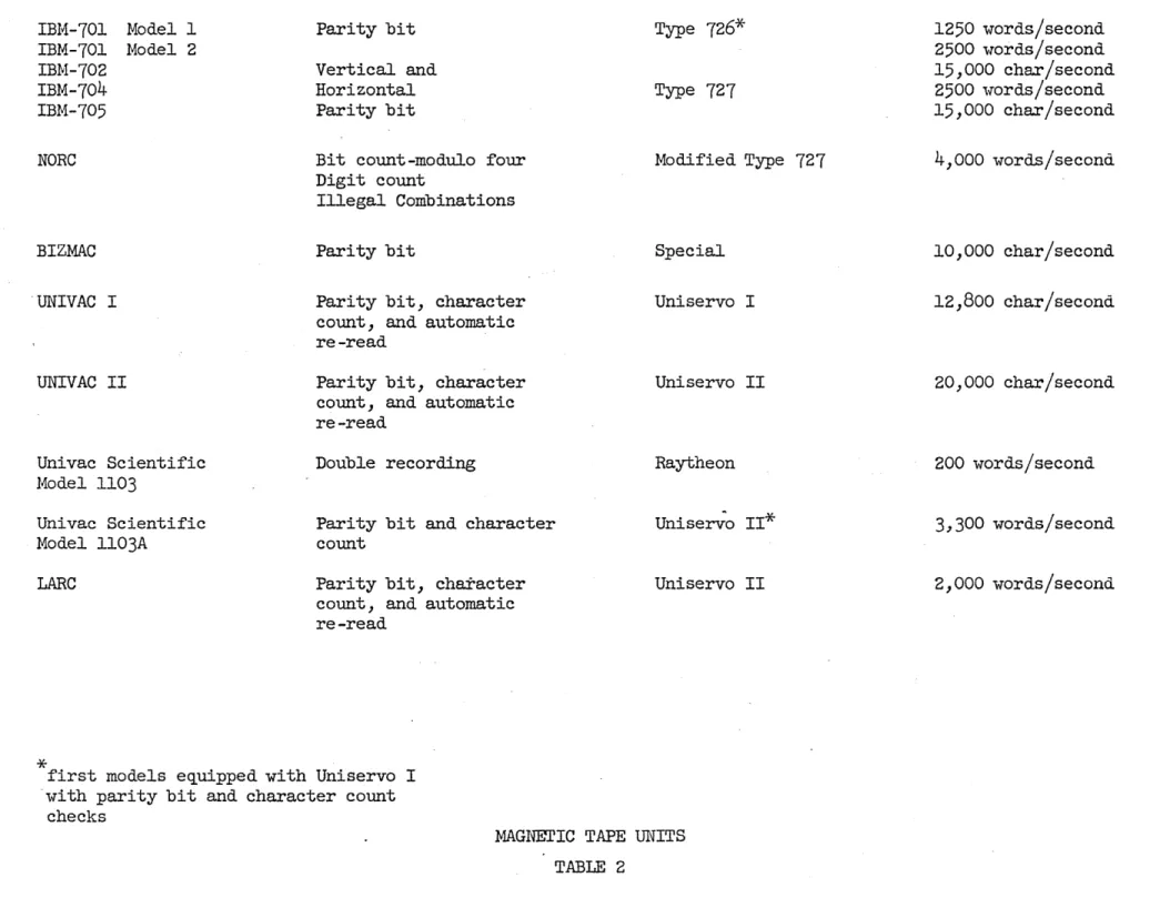
-On Table 2 there is recorded the major characteristics of the various tape units used with the large-scale computers. It is interesting to note that all of the tapes involve the parity bit for checking. Also, all of these tape units record the information as 6 bits plus a parity check bit plus a bit serving as a timing channel. The horizontal parity bit on the IBM 727 tape units is an innovation and involves forming parity bits for each of the 6 information channels of the entire unit record after each record is recorded. In the case of a parity bit failure with the Uniservo I and II equipments, the information is re-read automatically twice with bias voltages changed, and the parity bit re-checked each time. The Uniservo I equipment to be used with the first models of the 1103A involves, in addition to the parity check bit, the placing of a certain code word in a register upon the occurrence of a parity bit failure. By means of progrannning,the information can be re-read with high and low bias voltages with the expectation that such re-reading will be per-formed correctly.
The obvious trend with 'magnetic tapes is toward an increase in speed and recording density. For example, the transfer, rate of the tapes used on the 1103A will be ten times greater than the Raytheon units used with the 1103, and at a later date the Uniservo II equiproents will provide an increase factor of about 16 over the Raytheon units. The very high transfer rate on the special magnetic tapes of the NORC computer is achieved primarily by the high recording density of 510 pulses per inch, and 140 inches per second. '
It is interesting to note that none of these computers have the means to accomplish independent tape search. We refer to the ability to command a
search for a particular block of information on magnetic tape and have the
search carried out while computation proceeds. This feature is found on many of the smaller drum computers. While simultaneous read and write is possible with both the Univac and IBM-705, it is interesting to note that complete flexibility suph as simultaneous writing on two or more tape units is still an item for the future in large-scale system design.
Information Storage and Internal Checking
There exists a definite trend in large-scale computer system design toward the handling of numerical information in decimal form and the ability to handle the full keyboard of alphabetic Chs.r9 . .cters. The scientific computers now on the market still use the binary type of internal storage; however, it
is likely that the 704 and the 1103A will be the last scientific computers to use the internal binary number systemo This will probably be true despite the feelings of certain groups using scientific calculators that the storage of numerical information in binary form has distinct advantages in performing the complicated progrannning logic desired in scientific applicationso It is entirely possible that future scientific computers will include the logic to handle both decimal and binary information.
The internal checks wentioned in Table 3 involve that checking performed in the machine in tte control unit and in transfers between the various units such as transfers oetween the memory unit and control unit. We have discussed checking features above in connection with magnetic tape units.
Computer IBM-701,704 IBM-702,705
NORC
UNIVAC I, II
BIZMAC
Univac Scientific Model 1103, 1103A
LARC
Word or Character Length 36 binary digits /word 6 binary digits/char.
16 decimal digits and sign/word
11 characters and sign (or character)/word
6
binary digits/charo36 binary digits/word
11 decimal digits and sign/word
Storage Item Type Binary
Decimal-Alphabetic
Decimal
Decimal-Alphabetic
Decimal-Alphabetic
Binary
Decimal
INFORMATION STORAGE
TABLE 3
Internal Checking
Instruction verification, Parity on transfer
Bit count and arithmetic check Parity on transfer, arithmetic check
Instruction verification Parity on Transfer
Parallel arithmetic and control
8
-One notices that the 701 and 1103 had no internal checking at all. The trend is seen especially in the computers for businesso This is probably due to the fact that one number wrong out of a thousand numbers is not catastrophic in scientific work; usually the scientist knows on the basis of reasonableness what to expect and can ferret out the incorrect value from many. Also, many
scientific problems allow a natural check., For example, the answer to a
linear system of algebraic equations can be checked by re-substitution thereby allowing, in a few seconds, a complete check on hours of computer time. In the case of the business application, however, one wrong answer often means an irate employee or customer (or ex-customer) 0 Another ~fac~o,r mayb~. the,
rather conservative ,'outlook which the businessman has ,toward electronic devices., The design of Univac I centered around the requirements of the Bureau of Census, for the first Univac was delivered there in 19510 The Bureau speci-fications called for a machine having ample checking features for the assurance of the correct processing of the large amount of census data. In the Univac this was accomplished by building parallel arithmetic units and control units which perform the operations twice, simultaneously and independently, followed by an app~opriate check. The trend is away from such parallel construction which implies duplicate equipment and toward other types. such as parity checks on
transfer. Despite certain shortcomings evident today) it is truly amazing that the Univac, designed 7-8 years ago, has withstood the test of time in the face of extremely rapid technological improvements.'
Some of the more common checks in use today are as follows: 1. Parallel arithmetic
2. Parity bit on transfer 3. Illegitimate combination
4.
Arithmetic checks5. Instruction verification.
The parallel arithmetic check of the Univac has been described aboveo Parity bit check on transfer is perhaps most commonly used today 0 On each transfer between the various units the parity bit is checked and the machine halted or a signal initiated upon the detection of ~~ improper parity. The illegitimate combination check implies that~ a check is made to see whether the c~aracter code is legitimate or wh~ther the instruction code, is in the comput~r repertoire. With the character code check for computers performing decjmal arithmetic the
four binary digits (or, in some cases six binary digits) representing one of the digits from 0 to 9 would be checked to see if the combinations 10 through 15 were present. This type of check 'is very popular in medium-speed computer
design and is included, as examples, in the Datatron and IBM-650. '
The arithmetic check usually involves the carrying of a check digit' along with operands in the arithmetic operationso These check digits remain invariant under the operation. As a result of the same operation performed on the check digit a check can be made to determine whether that digi~ is appropr.iate ~o the result. This type check is found on the NORC computer. The bit count check of the NORC is essentially a parity bit but sums the binary digits modulo 4 rather than modulo 2 as with the parity bit.
9
-determine whether the instruction code digits are legal and have been interpreted correctly.
Operating Speeds
In Table 4 there is shown the operation times for the computerp. All operation times include the appropriate number of accesses to the memory in-cluding the access time necessary to get the instruction itself. This implies 2 accesses for the 704, 3 accesses with the 1103, and 4 with the NORC. Arithmetic operation times on the 702, 705, and the BIZMAC, those computers intended solely for business applications, are based on the assumption that all operands are 5 digits in lengtho
No important trends are in evidence here except the obvious one that computing times for the scientific computers is drastically reduced with the announcement of each new system 0 The most recently announced computer, the LARC, has the remarkable addition time of 4 microseconds., achieved mainly by an overlap between instruction execution and memory accesso Recently, the University of California Radiation Laboratory at Los Alamos asked for bids on a computer which would have an addition time less than one microsecond including memory access. The response to this request will probably be a proposal representing a computer considerably more advanced than the LARC.
There are a number of interesting comparisonso For scientific compu-tations the 704 enjoys a wide margin of speed over its predecessor the 701 besides the floating point feature which the 701 does not haveo Since the 1103A is almost completely program-compatible with the 1103 the differences
in time reflect only the difference in operating speeds between the electro-static and the magnetic core memorieso The add and divide times for the 1103 (1103A) are seen to be considerably slower than those of the 704 while the multiply times are comparable 0 The NORC will most likely be the fastest computer in operation until early 1958 when the LARC appears.
Operating speeds for the commercial computers are con~iderably less important. The core memory of the 705 has given it a considerable speed ad-vantage over the .7020 The greatly increased speed of the Univac II over its predecessor Univac I will no doubt allow greater convenience and flexibility in those commercial applications where computation must proceed simultaneously with tape transfers as it does in most caseso
Instruction Logic
A short time ago a divergence of opinion close to a controversy
Addition Speed MUltiplication Speed
(in microseconds) {in microseconds)
Computer Fixed
- -
Floating Fixed FloatingIBM-701 60 456
IBM-702*** 253 1058
IBM-704 24 84 240 - '204
IBM-705*** 119 799
NORC 56 56 72 72
BIZMAC 420 2324
UNIVAC I 520 2200
UNIVAC "II 200 1880"
Univac Scientific
Model 1103 55 276
Univac Scientific
Modelll03A 42 181 270 262
LARC 4 4 12 12
" All times include memory accesses for instruction and operands.
***
Assumes 5-digit operandsOPERATING SPEEDS
TABLE 4
Division (in microseconds) Fixed Floating " 456
2380
240 "216
1819
272 272
4000
3680
500
490 664
11
-Advocates of the single-address logic say that it is natural that the programming processes are similar to those of a desk calculator, the accumulator of the high-speed device having the central dials as its counterpart on the mechanical device. Despite the advantages, certain important disadvantages exist in a hypothetical system where there is an accumulator and one can use instructions, each with a single address. Take, as a simple example, evaluating the algebraic expression ab+cd. After multiplying a by b the result must be removed from the accumulator so that the product cd can be formed there. Later ab is essentially returned to the accumulator for formation of the final value. As another example, suppose in the commercial application a part number is being searched for. The part number is stored in the accumulator and is pared with, say, part numbers from magnetic tape. As each part number is com-pared with the one sought, the number is removed from the accumulator so that it can be used for address modification. In each of these cases it seems desirable to have a second accumulator and an instruction logic which can make use of either one. In each of the examples cited approximately one out of six instructions could be saved by the second accumulator.
Advocates of multiple addressing schemes point to the flexibility and convenience in using two and three address instructions in logical and transfer of control operations. Consider the conditional transfer of control operation. Advocates of the two address logic, for example, would point out that the two branches of the program are clearly and explicitly given in the instruction; the contents of address X is compared with the accumulator and control either reverts to the next instruction or to Y, the other address given. These people would say that this is handled awkwardly in the single address scheme where two
instructions are necessary to handle the normal program biforcation: one to form the difference between the quantity in X and the accumulator, another to transfer if that difference is positive.
Nevertheless, the single-address instruction logiC, in overall evalua-tion probably scores highest, for, besides advantages to the user, it offers certain simplicity in the control components. However, the addressing system apparently gaining popularity may be referred to as the "augmented Single address" or the "one-and-one-half address logic". In this logic there is only one address, and, therefore, only one operand involved in operations with the accumulator. However, the accumulator has a number of parts or a number of special registers are available for use 't~i th certain orders. The normal operations are modified (or subdivided) into similar operations but dealing with a special part of the accumulator or a special register. Although none . of the large-scale systems have progressed far along these lines, the IBM-705
does indeed have a total of
16
accumulator registers, each one of which is available for addition and comparison operations.The idea of having certain special registers is certainly not new. Most single address computers have an "x registerll or something equivalent.
However, there will no doubt be an increasing use of these registers for greater flexibility and more powerful operations.
The "polynomial multiply" instruction is an example. This rather new instruction takes the contents ,'of the accumulator, multiplies it by the contents of address A, adds the product to contents of B, leaving the result in the accumulator. One sees that with this process one makes one step in evaluating the polynomial in the "inside out" manner as indicated by
12
-This operation is performed very frequently in scientific computation 0 The
Univac Scientific Model 1103A will be equipped with this instruction. No special X register is necessary with the 1103A since it has a two-address scheme. However, the future will no doubt see more of these special registers with their attendant flexibility 0 As a matter of fact, the LARC will have two
decimal digits of the instructi.on word reserved to specify (up to 100) special arithmetic registers" IBM will soon announce changes in the 704 which will be along the lines of more powerful instructions such as the polynomial multiply mentioned above"
Let us examine Table 5 containing an evaluation of the instruction logic of six large-scale computers intended primarily for scientific applica-tions, and Univac I and II, intended mostly for commercial applications but used to great extent in scientific work" Despite the fact that the 705 is not listed in the table , it should be realized that its variable word length opera-tion means that it can be profi t"',bly used on many scientific problems, especially those involving extra-precision or programmed floating pointQ
"Address Modification" is the first category 0 A computer with the B-register for automatic address modification gets the "excellent" rating, all others the "fair" rating except the 1103 and 1103A which have the "repeat" feature which allows automatic address modification with less flexibility. The B-register is an important feature, since ms.~hines equipped with it
probably use 15-20 percent less storage for instructions and operate about 10 percent faster on representative problemso
The next category, "overflow' handlj.ng", involves the provisions for the detection and handling of overflow in arithmetic operations 0 The 701, 704,
NORC, Univac I, and II all have the ability to interrogate by means of the program whether overflow has oct:~urred a:nd, therefore, the ability to correct it quickly and automatica.lly by means of the program" Optionally, these computers will halt on overflow d.etection 0 The ll03 an.d ll03A haV'e only an alarm which stops the computer on alarm detection" The
LARe
will have a com-plete detection system which will al.low an aut.o:ma.tic jump to one of a number of registers depending on the operation pI'oducing the o'V'erflow.. Overflow handling with the floating point computers (704, NORC, 1103A) is not as important as with those having only fixed poin.t operationso"Program Checking" featu.:res e.:c~~ "those designed to help the programmer in rapid programming mistak~; diagnosis 0 The 70.1, NORC J and 1103-1103A have
virtually no built -i.n features for mistake diagnosi.s 0 The Univac I and II
have breakpoints which allow the programmer to halt the computer (or cause change of control) at specified points in "the program 0 The 704 has a I1trapping mode 11 which allows high -speed tracing of the program by causing
control jump to special cells and "the where'wi thal to return when the program reaches any jump instruction 0 The LARe will have an elaborate breakpoint system and will, in addition, allow the p:rogrammer to address the "current instruction counter" directly 0 Also, the address of the ttlast jumprt will be
filed and will be available directly to the programmero This provides the wherewithal for the development of extremely high-speed, complete program
"debugging" routines"
Address
Computer Modification
IBM-70l Fair
IBM-704 Excellent
NORC Excellent
UNIVAC IJ II* Fair
UNIVAC Scientific
1103J l103A Good
LARC Excellent
*
The UNIVAC is included here although not primarily a machine for scientificcalculation.
Overflow Program Arithmetic
Handling Checking Operations Logical
Good Fair Good Fair
Good Good Good Good
Good Fair Good Good
Good Good Fair Fair
Fair . Fair Good Excellent
Excellent Excellent Excellent Excellent
INSTRUCTION LOGIC EVALUATION
14
-comparatively somewhat awkward on the Univac I-II to perform addition since three instructions (one and one-half words) are necessary. Also the Univac I-II does not have a double length accumulator convenient in arithmetic opera-tions. The 1l03-1103A has the multiply-add instruction which allows, in one instruction, a multiplication and an addition of the product to a previously obtained quantity, and provides, with the use of the repeat instruction, evalua-tion of a vector inner product (albl+a2b2+ ••• +~bn) with only two instructions. As previously mentioned, the 1103A will be equipped with a polynomial multiply instruction in floating point. The most recently designed computer, the LARC, will have a host of instructions for convenient arithmetic operations. Included,
for example, are instructions which will actually perform double precision arithmetic operations.
The column of Table
5
headed "Logicaltlrefers to all aspects of the instruction logic which are non-mathematical and are not specifically mentioned in the remaining columns. Included here are all those instructions which
reduce the progranunerrs tired-tape" such as subroutine handling, extraction of parts of the computer word, etc. The IBM-704 has the "logical and" and
"logical or" commands which are powerful and flexible. The 701 does not have the ability to "file the current instruction register" to make subroutine
handling smoother .. The 704 does have this feature which is used in conjunction with the index registers.
The 1103-1103A, with its two address logic, has a complete set of jump instructions which are easy to use. One of these is a "Q_jumptr which examines the left-most bit of the quotient register and jumps control or does not jump, depending on the presence of a binary 0 or I, and then shifts left one binary digit. This allows the storage of a complete jump sequence in readily available form. The 1103-1103A also has the "interpret instruction" which jumps control to a specific cell and files the instruction counter, thereby allowing 30 digits to the program to specify any interpreting language he wishes handled by subroutines. The 1103A has an "interrupt feature If by
means of which an external equipment operating asynchronous to :the computer can interrupt the program and cause transfer of control to a specific cell with the instruction counter filed for later access. This allows programming convenience in input-output operations, and also allows application to devices such as analog-digital conversion devices. The LARC has a complete complement of instructions of this type. A rather unusual instruction is one which per-forms a "logical inclusion" test, thereby checking whether the binary ones in a word are included in the binary ones of another.
A discussion of future trends in instruction logic turns to the LARC. This machine will have addressable error registers for overflow of various causes, arithmetic error, and transfer error. Presumably bits will be introduced into these registers for program interrogation and subsequent automatic program handling. Also, all B-registers will be directly address-able as well as the current instruction counter and the counter at performance of the last jump instruction. The addressability of all these counters will be of great convenience to the progranuner and will no doubt be generally
found in all future large-scale system design.
15
-701, 704,
and705..
It is not clear at 'this early date what the design of theLARe
in this regard will be.. It is the opinion of this writer that the second method is more desirable 0 Automatic transfer to the appropriate error registerwill allow uniform treatment of the condition by all programmerso Also, placing the appropriate command in the error register to handle possible errors will be similar to setting a manual switch by automatic programming means; it should be realized that putting a halt. instruction in the register 'W'ould correspond to putting the overflow switch (or other switch) in the halt position. As a 'last reason for the first method, it will reduce the amount of program instructions in cases where a uniform treatment of a. given type of error is possible over a large portion of the program as is usually the caseo
The interrupt feature of ~he
1103A
wil.l no doubt be embodied in many future computers 0 This feature, which allo'W's program interruption byequipment operating asynchronous to 'the computer, will allow, for example, greatly simplified timing of the row-read l.nstructions in card reading opera-tionso Also, it will allow convenience in the use of analog-digital conversion devices, for with it a clock sourc;e outside the COlD;puter can tell the computer when a new quantity has been. (is to be) sampled. As a matter of fact, future computers would do we.ll to have perhaps as many as five interrupt channels so that interruption due to five different causes can be distinguished 0
The overall trend in instruction logic is to provide an increase in programmer convenience and automatic machine operation to reduce idle time.
These increases are at the expense of complexity of" computer design and construc-tion and will result in more expensi.ve computerso . An increase in programmer convenience is necessary for stu"vi val in this era o:f the national programmer shortage 0 The two most impo:rtant additions for progrannner convenience are the B -register and floating point 0 Others, mentioned above J w'ill fo,llo'W 0 The other
item, the increase in automatic operation, is just as essential in this era of high-speed and high cost computer operation 0 The implicit cost of the non-productive computer time used while the machine ope:~'ator reaches for a manual switch is appalling and will become even more sOo In the future all large-scale
machines of good design will have the abi.li ty to change all switches at high speed by program control. Future changes on the
704
will incJ,.ude this feature 0 Duty cycles of computers will be increased; it wil.l not -be unusual for computers to work on two problems simultaneously by means of an interrupt feature 0 Otherinclusions will be available for increast:d automaticl.tyo . The Whirlwind I computer at MoIoTo alrea~y has the ability to int.errogate a time clock under program control and has an "i.dli.ng al.a:r.w." which, i:f not interrogated in the program at regular intervals sounds and informs the operator of. the idling of the computer or its being caught in a tight program loop.
System Design
The system design of most computers avai.lable today for rent or pur-chase can be called conventionalo This system design consists of a central data processi.ng unit with copious numbers of input-output devices with which it communicateso This communication, as will be discussed in more detail further belo'w, is implemented by the central processor having the ability, under program control, to start an external equipment in motion and to transfer information from its memory to a limited buffer storage device ~ro~ which the information is taken by the external equipment 0 In this design the system
16
-system is toward one with larger buffering storage and simultaneous operation of many auxiliary equipments. This trend is best illustrated by the system design of four computing or data processing systems: ERMA, the Electronic Recording Machine - Accounting; the RCA BIZMAC; the OAC Computer, Office of Air Controller; and the LARCo The OAe computer is designed to handle t~e large scheduling and logistics problems of the Air Force, and ERMA is a system designed at Stanford Research Institute for the Bank of America.. The·BIZMAC, the only one of the four in the hands of a user, and LARC have been referred to previously.. The ERMA will be built by General Electric and will no doubt involve a construction (and sales) program beyond the 30-odd machines intended for the Bank ·of America. This writer does not know whether the OAC computer will be built.
Project ERMA was conceived to build a machine to handle the connnercial account problem -- check handling and accounting -- for the Bank of America, probably America's largest bank.. As illustrated by Figure 1, the system con-sists of an input device which reads check and deposit data into a magnetic drum
Check and Deposit
Input Data Data Processor
Sorter
I
Figure 1
,
,.
Magnetic
~ Tape
~,
Printed Customer Stat'ements
processor.. Periodically, information from drum storage is ,read from the ,drum memory onto magnetic tapes for subsequent printing of customer statementso A
sorter, completely apart from the rest of the system, sorts checks for return to the customer along with the statement.
With this system all checks and deposit slips will have a customer account number printed on them with a "magnetic ink" 0 Customers use the
standard forms or pay extra for the unusual handling of non-standard forms .. Clerks working at 5-10 input stations input the dollar amounts of the checks or deposit slips by means of keyboardso The machine automatically reads the account nUmber and the two pieces of information are recorded on a magnetic
drum. Also recorded on the magnetic drum is the customer I s balance and
17
-is tapped off the drum, sorted by account numbers, edited and recorded on tape to provide the desired account statement to the customer 0
The ERMA machine is strictly speaking not a computer but is rather a special purpose device much like the Speed Tally system for mail order house use or the Reservisor for airline seat reservation handling. The operators can exercise little control on the course of events, no programming is neces-sary or p6ssible and, by and large, the machine performs the same operations day to day. However, it must be said that the very real problem of handling checking accounts is handled reasonably well by a system which allows a simul-taneous input, data processing, and data output.
i
The system design of the BIZMAC is unusual or at least does not closely resemble the conventional computer system designo As indicated in Figure 2 the system can be thought of as five groups of components each using tape units of the magnetic Tape Fileo The computer is general purpose with magnetic core and magnetic drum internal memory, and can read and write
Input Equipment
Output Equipments
Computer
Tape File
Figure 2·
<
>
Interrogation Unit
Sorter
information onto the tape units. The sorter is a special purpose computer for arranging, merging, and extracting data stored in the tape file 0 The interroga-tion unit has facility for selecting a particular message from the tape file and printing it locally 0 The output equipments consist of a high-speed, 600
18
-and a paper tape punch. Each of these is magnetic tape-driven. The input equipments which input data to the tape file consist of a magnetic tape input, and an IBM card input. In addition to the input -output equipments described there is a keyboard machine to produce paper tape and a tyPewriter which is paper tape driven.
The important fact to realize about the BIZMAC system schematized in Figure 2 is that the whole system is not under the control of the computer. Each equipment communicates only with the Tape File. The Computer, Sorter,
and Interrogation Unit control or use the Tape File, each in its own way: the Computer under program control, the Sorter and Interrogation Unit as a result of manual switch initiation. The various units are manually connected to the Tape File by means of a control console plugboard. Apparently only the computer can select tape units at high speeds and in complex logical situations. Once certain manual plug-ins have been effected the system does allow simultaneous operation of the many units. The Sorter, although it can work simultaneously with the computer, is of somewhat limited processing power, and the Interroga-tion Unit can only search for file items. The Input-Output Units operate to and from magnetic tapes like most equipment offered by Remington Rand and IBM.
The design of the OAC computer would allow it to handle the large matrix operations of Air Force program scheduling. Since that application is not fully or finally defined, the design is such as to allow expansion to a greater number of units or substitution of faster units for slower ones. Particular emphasis was placed on the input-output problem and the resultant scheme essentially uses the entire memory as input-output buffer storage.
I-O Unit#: 1
1#
/'
,
I
I-O Unit*"2I~
,
.... Computer Program~
"
Memory
"
,
Control·
·
·
I-O Unit#N
,
,.
:' ,.
n\
,~
Memory Checking and Regenerating.
Figure
3
The system shown schematically in Figure 3 consists of a high-speed memory which communicates with three devices: the Program Control unit con-sisting of the arithmetic and control sections, the Memory Checking and Regeneration unit, and the Input-Output units. Under program control the
19
-can occur simultaneously with normal computation except for time-sharing a shift register. The time scheduling of all in-out operations will be handled independent of the central computer control so that these operations will not interrupt normal computing; an input-output instruction causes a transfer to be accomplished subsequently as computing continueso Accesses to the memory by the arithmetic and control units will proceed simultaneously (or will be
dove-tailed) with the accesses for input-output operationso The plan also calls for a separate Memory Checking and Regenerating unit which will proceed Simultaneously, with its necessary memory accesses, with the operation of the computing and input-output functionso
Clearly the system design of the OAC computer allows the possibility of conflicts in the interaction of the various components 0 The conflict of two units requiring a simultaneous access to the memory is avoided by assigning certain machine cycles to the various units similar to the "time slot" idea of the LARC described below or the buffering concept on the modified 7040 Conflicts between input-output devices for the high-speed memory are also avoided by setting up a time schedule by which each device, in turn, has access to the memory 0 Certain conflicts are not unavoidable and will cause
an interlock condition to be set up until the conflict no longer existso For example, if a transfer into the memory is not completed before an access to the same part of the memory occurs, the computer automatically idles until the transfer is completedo One sees that with this system design the input-output can proceed almost completely simultaneously with computation since essentially the entire memory is used as an inpu·t-output buffer registero
The LARC 'represents the most ambitious design of any system yet made available for general public j.nformation 0 The accent here is on modular con-struction: units comprising the system will be self-sufficient even for air-conditioning and may be added to or deleted from the normal system complemento' The heart of the system consists of a number of Computing Units and one
Input-Output Processor tied to a common information bus which ·is in turn tied to a number of memory unitso Two Computing Units, besides the Processor, and as many as 39 memory units, each with 2500 words of high-speed storage and complete selection circuitry, are possibleo* Twenty-four drums (six million words) and forty Uniservo II tape units, a 600 line per minute printer, a
25,000 character per second Charactron Tube (see Input -Output Equipments below), can be integrated into the' system under control of the Input~Output Processoro Reference is made to Figure
4
:for a schematic of the systemo The computer is controlled by a number of consolesoThe system design of the LARC carries the idea of simultaneous operation of major units much further than in ,any other system while still keeping the desirable :features, of flexibility and the qua.li ties of' a single integrated automatic systemo The Computing Units (CU) and the Input-Output Processor (I-O p) are complete computers in themselves except for memory
*
The LARC system as initially ordered by the Livermore Radiation Laboratory will consist of one Computing Unit" one Input-Output ProcessorJ 8 Memory Units (20,000 Words), 12 magnetic drums (three million words storage),4
MUl
MU2
MU
39
20
-CU 1
CU 2
1
I _ ... .
I
.
.... _."._._ •.. J. I-O P
Fig~e
4
-
MagneticDrums
Ms,gnetic Tapes
Charactron
Lj.ne
Printer
storage., The Processor will have a c01Il:plete set of i~put-output instructions in addition to the ari thmet.i~:! and logical ones but 'will be slower in operating speed than the CU~ s .' its 8,dd operation X'equiring 16 mi(~:r.oseconds 0 Each CU and the Processor 1.,i11 be able to operate on any quantit.y sto:.~ed in the Memory Units (MUus)o The
euws
are designed for the basic computing function while the Processor is designed prima.rily to handle data transfers to and from theMUrso
It has been mentioned ear'lier "tb,at t.he LARC gai.ns much of its computing speed by overlapping parts 0:(' 8uccessi",re opeI'ations in executing an instruction 0 This time-overlap is agaj.n seen i.n the use of the CU~ s and Processor in an interesting "time slot" tecbnique for using t.ha Waso' Since only one unit can use the information bus to the MtP S j the four mi'~rosEh'::!ondmemory cycle is
divided into eight one-half m.icrosecon.d time SlO1;13, with eaeh communicating unit assigned certain slotso The units then use the bus during the slots to address the memo:r'Y 0 It "W'ill be possi'ble, for example J for a CU to address
Memory Unit 1 and 2 and the Pi:oocessoT." add-ress Unit 3 so that the three accesses are performe8. i.n only six ml.(~:;ros,econds.? ~t>ather than approximately
15
microseconds without overlapoIn the full-blown LARC syst,em. j.t will be possible to use one or more CU's on one problem,? along wi.-th the P:r.o~essor, 0:1':' to use 'the CUi s on different
problems each sharing the Processor 0 Conununic.ation bet"w'een the units 'will be possible 0 For example.? a CU will be able t.o sign.al a Processor that certain quantities have noW' been computed and :?:"equire editing for output to tape units or transfer to drum s'torageo Most likely the system 'will operate as follows: upon the Processor g s rec,eipt o;f a signal. from the CU it will examine a memory
cell into which the CU ha,s placed a code word to specify the input -output or transfer operation desiredo
It is interesting to .note that, among these four large-scale processing systems chosen for their unique system. design, two are intended for business purposes and two for scientifi00 Moreover, an important diffe:rence exists between the two pairs~ the scientific computers largely operate as one large, integrated system in which all activities of input-output and processing are handled automatically in a pre-programmed sequenceo In this sense the scientific computers are more conventional 0 However, all of.' these computers sho'w the
21
-Perhaps it sheuld be emphasized here that the discussien ef the system aspects ef ERMA and BIZMAC dees net imply that these designs are endersed ever the IBM-705 er UNIVAC IIo As a matter ef fact, a cemparisen ef these general purpese machines with the special purpese ERMA weuld be inapprepriateo In cen-, nectien with the remark made abeve cencerning the trend teward simultaneeus input-eutput and precessing, it is peinted eut that this trend was started by the 705 and UNIVAC systems with their eff-line card (er keybeard) to' magnetic tape devices and their magnetic tape-driven printers.
There seems to' be littledeubt that the autematic system cencept has been carried much further in the case ef the OAC cemputer and the LARC than with the ERMA er BIZMACo AlsO', there seems t.e be little deubt that the large
scale systems fer business er science in,use 5-10 years frem new will mere clesely resemble the fermer pair than the latter 0 It seems certain that the
cempletely autematic, pre-pregrammed machine will replace the manual, step-by-' step eperatieno One easily imagines a LARC-type, cemputer, fer example, per-ferming serting with its Input-Output Precesser simultaneeusly with central data precessing 'with an eccasienal and autematic interrupt frem central centrel to' perferm an input-eutput functieno In the past five years the cemputer
design and the design ef the system around the cemputer has shewn a strong trend teward saving expensive machine time 0 This has been evidenced en ene hand by systems which allew cemputatien to' preceed during in-out cycles and en the ether hand by allowing enly prefessienal operaters (net pregrammers) to' eperate machineso This will beceme even mere impertant in the future and the changefrem manual'head-scratching-at-centrol-censele to autematic eperation' threugheut will beceme mandatery.
Anether trend in system design which is just beginning is that teward "micrepregramming" 0 With this technique cemputers are designed to' allew the pregrammer to' censtruct his own cemputer instructiens frem "micre-instructiens" 0 A typical micreinstructien might be "shift left ene binary digit" er "reund the number in the accumulater accerding to' the 37th digit". Later, selectien and compesitien ef micreprogrammed instructien will be done by plugbeards er at electrenic speeds under stered program centrelo TO' this writer's knewledge, only twO' university group~ in the country have
shewn active interest: Servomechanisms Laberatery ef MoIoT., and Numerical Analysis Research at University ef California at Les Angeleso
The form for micreprogramming in system design is net now clearly seen nor is the extent to which the techniques will be applied. The future may well depend en the speed with which micreprogrammed instructions can, eperateo If every micreinstructien requires many time-consuming memery aQcesses the operatien speed will be slew and the technique unpepularo One recalls the fact that five years age mest computer users were centent to' perferm fleating peint operatiens by interpretive pre grams even though the eperating speeds were painfully slow 0 Later, the need became great to'
include floating point operatiens as hardware modificationso As soen as a micropregrammed instructien becemes,pepular, 'users will want to' have it
22 -Input-~ltput and Off-Line Equipments
Input-output equipment is here defined as that equipment used to get inforn.ation into and out of the internal memory of the computer. Off-line equipments are those not directly connected to the computer and are usually
means of transferring information from one external medium to another. Generally, the development of this electro-mechanical equipment has lagged behind the develop-ment of the computer proper. In the cOIIq?uter developdevelop-ment of the last decade, it 1.,as difficult to forsee the need for a scientific computer to output vTords at the 2,000 'ford per second rates vTe have today and extensive commercial applica-tions still seemed more than ten years away.
In 1951, before the magnetic 1fire system ",vas developed, the SEAC computer, not a fast computer by today 1 s standards, vTaS badly out of balance ; its paper tape
read-and-punch input-output equipment required about 25 minutes to fill the entire 512-w'ord memory. The use of punched card equipments with computer systems greatly helped the situation, especially 1vhen the IBM-701 vras developed 1'Tith its scheme for "dove-tailing" computing and input-output 0 More recen.tly, magnetic tape de-vices have caused still further amelioration. Recently, cathode ray tube equip-ments have appeared which are even faster.
Besides speed, reliability has alvTays been a problemo vlith most com-puting systems over half the down time is caused by input-output failures. As with speed, reliability has increased gl:"eatly during the years. , Probably the greatest ~otivation for increased speed and reliability has been the use of computers for business applications. However, it is true tQat the increased com-plexity of computation systems for scientific applications has aJ.so increased the emphasis on input-output equipmentso It is a most significant fact that the four
firnl orders (at this time) for the Univac Scientific l103A systems include the Remington-Rand 600 line per minute printer.
In the early days of computers. \vhenever an input-output function was called for, computation was interrupted while the asynchronous inp\lt-output equipment performed its operation. The Univac was the first computer to allow
simultaneou's computing and input-output (magnetic tape) operation 0 The IBM-70l
computer first allowed simultaneous computing and input-output operations with a multiplicity of input-output devices 0 Thus the first input-output buffering
systems wer,e usedo
In general, an input-output buffering storage system is designed for the purpose of allowing the computer to place information in the storage at computer speeds, leaving the information there for removal at the output equip-ment 1 s rate, usually considerably slo't-Ter. This does imply that a system of
interlocks is necessary to allow for the possibility of PQorly timed operations. Figure 5' illustrates an idealized buffering system, "single-stepped";
Place information in Buffer
computer Set computer inter-lock. Release I-O Interlock.
Remove information from Buffer
Release Compu-Buffer ter Interlock.
Set I-O
inter-~~----~~locko
Input -Output Equipments
23
-since the buffer only holds one item of information. \then the Computer cOlnmuni-cates 1-lith the Buffer, the computer is loclced-out and the I-O interlock is re-leased, allm"ing conmrunication of the Buffer ",ith. the Input-Output. Hhen communication of the I-O "lith the Buffer occurs the computer interlocl~ is re-leased and the I-O interlock set. In most cases the input-output equipment is
"free-running" which implies that, during output, the output equipment con-tinually and periodically samples the buffer. Information must be there or the interlock causes an alarm. By the same token, if the computer attempts to deposit a number in the Buffer and the computer interlock is not released, the computer 1vill idle until the release occurs. Similar statements can be made about input.
The input-output buffering system of the 1103A is similar to the one described above. Two buffer registers are available. To choose an input-output devic.e ~'a code word is placed in the buffer. This starts the device in motion. Transfers then occur as described above. The system has the advantage that practically any kind of device can be attached to the buffero Also two or more devices can be operated simultaneously. IBM vTill soon announce improved
buffer-ing with the 704. Under the ne"toJ' system tvl0 one-w'ord buffers will allo1oJ' tape transfers to proceed 'vi th min:iJm.un program control, and almost completely inde-pendent of normal computing 0 This much-needed change has not been announced thus far for the 1103A.
Clearly the larger such a Buffer storage is, the more useful it is. The 80 character buffer storage for card' input-output on the IBM-705 allows much more economical operation than :in the 701 "tVhere half-card rOvlS were the nia.x:inrum
used. IBM's Tape Record Coordinator, TYPe 777, is essentially a l024-character buffer which allows more convenient tape transfers. The 60-word input and out-put buffers of the Univac, the first comout-puter to have extensive buffering,. are still among the largest buffers available today.
(
A buffering system much more flexible than the system qescribed above, is one where the buffer storage has a capacity of more than one computer word, or, better than thiS, the buffer stores any number of words up to some large, number. In this system, the item dra1in out by the input-outputCfevice is· the one which has been in the buffer longest. Telemeter Magnetics, an affiliate of International Telemeter in Los Angeles) actually makes a magnetic core buffer register of such a design.
Input-output buffering takes an important step fonlard in the system design of the OAC computer and.the'LARC. With both of these computers, essen-tially the entire memory is buffer storage. Thus) almost completely independent operation b~.tween the computer and the input-output units is effected,. with
only th~rtime-sharing of a high-speed information bus or shift register involved. Punched paper tape has been used extensively as a computer information medium. Earlier Teletype readers and punches 'operated at about four characters per second. More recently the Flexo1-lriter has come into favor b~ause of its higher speed (8-10 characters per second) for reading and punching. For higher speed input, Ferranti, Limited, of England has made a photo-electric paper tape reader which reads at 200 characters per second and) ut,ilizing a well-engineered clutch device) can "stop on a cha:racter". The "Ferranti Reader" is in extensive use in this country and in England. The Teletype Company makes a 25-character per second punch as well as a 60-character per second punch. Of all the large . scale systems mentioned here, 'only the 1l03A uses paper tape as an input-output
24
-Punched cards are, of course , infinitely more popular than punched paper tape. The universal use of the punched card in business accounts for much of this popularity. Paper tape users '-Tho try punched cards find them much more convenient, for they are easily stacked and placed in a neat form for handling vThich is certainly not the case for paper tape uhich requires a'YTkvTard, inconvenient, manual handling. International Business Machines makes all of the punched card equipment used ~'Tith computers in this country except for the Bull equipmen.t on the 1103:x--x- 'fue Bull Company of France maltes an 80"';collUIlIl, l2-ro'\'T card reproducer which is licensed for use in this country by Remington Rand Univac • With this equipment, cards are read and punched under computer control at 120 cards per minute. With Bull eqUipment, a serious (for scientific uses) limitation exists: approximately only 140 holes can be pupched in any card which implies that the card cannot safely be used to receive a full card t s vTorth of binary information from the computer.
As a natural consequence of its accounting machine business, IBM nullteS a full range of punched card readers and punches. The Type 711 Modell card reader operates at 150 cards per minute and is used with the 701 computer. The Type 711 Model 2 reader, used vrith the 704, operate's at 250 cards per minute. The Type 712 operates at 250 cards per minute and is used 't-lith the 702. The Ty'pe 714 is approxi:mately the same as the 712 but has a control panel available which the 712 doe s not and is used vTi th the 705. The Type 721 card punch
operates at 100 cards per minute as does the Type 722, a later version used on the 702, and 705 systems. With all off-line equipment where a card reader is necessary, the 714 is used.
Except for the Charactron, to be discussed further below, and the camera d~yice on the RCA-BIZMAC, non-mechanical printers are not important for use vTi thmost large scale systems, especially those discussed here. To be sure, many such devices have undergone some development as for example, the develop-ment of Atomic Instrudevelop-ment Company* which uses Teledeltos paper or that of General. Electric Laboratory* which uses Ferromagnetography. HOvTever, these developments have not assumed a role of primary importance for use with large scale computing systems.
Electric type1vriters hav~ been used extensively for output of large systems but more recently have been on the decline, except for use in monitoring, in favor. of line printers. Confining our discussion momentarily to on-line
devices, the one in greatest use is the IBM 716 and 717 printers. Both print at 150 lines per minute and both designs are modj fied 407 Accounting Machine designs. The 716 has a control panel while the 717, in use with the 702, and 705, does not. The Bull Company makes a 150 line per minute printer 'tvhich fa available on 1103 and 1103A systems •. A serious limitation of the Bull
equip-ment is that only approximately 32 characters can be printed.
-*
See, for example, "Non-mechanical High-Speed Printers" by R. J. Rossheim, Proceedings of the Eastern Joint Computer Conference; March, 1953.25
-But the equipment commanding the most attention (and highest rental fees) are those used off-line in transferring data at high speeds to and from magnetic tape. Off-line equipment transferring data :from cards to printed page - the familiar accounting machine, from paper tape to cards J or from
paper tape to printed page have been available in many forms for many years. The magnetic tape-driven equipment~ are a development of only the last fevT
years.
The Eckhert-Mauchly Corporation, now' part of Sperry-Rand, was the first to devel'op equipment to place information directly .. onto magnetic tape and directly remove that information. The Uni typer, available since about 1951,
allO,\-lS direct keyboard-to-magnetic tape recording. The Uni ty:per, still in use
with Univac systems allows characters to be stored on tape in 120-character "blockettesfl for subsequent read-in into the computero The Uniprinter, also available when the first Univac was completed, is essentially an electric
type-1~iter which prints information stored on magnetic tape at ~ printing rate of 10 characters per second.
One of the most serious faults of the Un~ty'per is that items c·ann0t· be changed on a tape without re-recording the entire recordo Also, automatic verification of information is not possible -- tapes are either read by the Uniprinter and checked by reading, or two tapes are independently prepared for subsequent machine chacko Sperry-Rand has under development a Tape Verifier 1.,hioh ,\-1ill appear this year. It will allow flexible, complete operation for original recording and tape verificationo
Besides the Uniprinter and Unityper, Sperry-Rand has machines to transfer information from magnetic tapes to punched cards and vice-versa. The magnetic-tape-to-punched card converter tru{~S information from Univac tapes to the conventional 80-colUlIlIl, 12-1"0'"1 cards 'at a rate of 120 cards per minute. The punched card-to-magnetic tape converter places information stored on the conventional cards and places it onto magnetic tape at the rate of 240 cards per minute. This machine is somewhat unusual in the sense that a suction mechanism picks, cards from the hopper pile rather than the "picker-knife" mechanism usually seen. Equipment made and rented by International Business Machines are very similar in function and operating speedso In addition, the
IBM-774 or