NOTICE
The information contained in this document is believed to be accurate in all respects but is not warranted by Mitel Networks Corporation (MITEL®). The information is subject to change without notice and should not be construed in any way as a commitment by Mitel or any of its affiliates or subsidiaries. Mitel and its affiliates and subsidiaries assume no responsibility for any errors or omissions in this document. Revisions of this document or new editions of it may be issued to incorporate such changes.
No part of this document can be reproduced or transmitted in any form or by any means - electronic or mechanical - for any purpose without written permission from Mitel Networks Corporation.
Mitel Networks is a trademark of Mitel Networks Corporation.
Windows is a trademark of Microsoft Corporation.
Other product names mentioned in this document may be trademarks of their respective companies and are hereby acknowledged.
Mitel Networks 3300 Integrated Communications Platform
Technician’s Handbook
Release 3.3 51006266, Revision A
April 2003
£,¥ Trademark of MITEL Networks Corporation © Copyright 2003, MITEL Networks Corporation
Table of Contents
List of Figures . . . xiii
List of Tables . . . xv
Chapter 1 :
Introduction
About This Handbook. . . 3Purpose. . . 3
Audience . . . 3
Contents . . . 3
Symbols Used in this Handbook . . . 4
Important Safety Instructions . . . 4
About the 3300 ICP . . . 5
Network Configurations. . . 5
Software Tools . . . 6
Additional Documentation . . . 7
About the 3300 ICP Documentation . . . 7
Getting 3300 ICP Documentation . . . 8
Access Online Help . . . 8
Access Mitel Online . . . 8
Get 3300 ICP documentation on Mitel Online . . . 8
Get User and Installation Guides on Mitel Online . . . 9
Create telephone User Guides with Manual Maker . . . 9
Contacting Mitel . . . 10
Sending Us Feedback. . . 10
Contacting Mitel Networks . . . 10
Contact Mitel Networks Order Desk. . . 10
Contact Mitel Networks Repair Department. . . 10
Chapter 2 :
Installation
About This Chapter . . . 13
Installation Overview . . . 13
Installing the Controller . . . 14
Overview . . . 14
The Maintenance PC . . . 15
Installing the Controller Hardware . . . 15
About the 3300 Controller . . . 15
Install the Controller Hard Drive . . . 17
Install the System ID Module. . . 18
Install the DSP Module(s) . . . 19
Connect the Maintenance PC to the Controller. . . 20
Turn on the Controller . . . 20
Verify the Connections . . . 21
Program the License and Option Keys . . . 21
Connecting the Controller to the Network. . . 23
Overview . . . 23
Set the Controller RTC IP address . . . 23
Program the Controller DHCP settings. . . . 25
Verify the Operation of the Controller . . . 27
Configure the Layer 2 switch. . . 28
Installing Service Units . . . 29
Overview . . . 29
Installing 3300 Network Service Units . . . 29
Install an NSU . . . 30
Install a BRI NSU . . . 34
IMAT . . . 35
Installing 3300 Analog Service Units . . . 44
Install an ASU . . . 44
Installing Peripheral Units. . . 48
Overview . . . 48
Unpack, position, and ground the Peripheral Unit. . . 48
Connect the fiber cable to the node . . . 49
Install the power converter . . . 50
Install the Peripheral Interface cards. . . 51
Cable the node to the MDF . . . 52
Overview . . . 60
Install the Peripheral Slot FIM Carrier . . . 60
Install the SUPERSET Hub . . . 61
Installing Digital Service Units. . . 63
Overview . . . 63
Unpack, position, and ground the DSU Node . . . 63
Connect the fiber cable to the DSU . . . 64
Install a DSU card . . . 65
Install the interface assembly on cards . . . 66
Install the BRI Card . . . 67
Install the Formatter Cards (CEPT, DS1) . . . 69
Install the PRI. . . 73
Install the Peripheral Resource Card . . . 75
Install the R2 Card . . . 76
Program the DSU. . . 79
Installing Phones and Peripherals . . . 80
Installing Phones. . . 80
Programming Phones . . . 80
Programming Voice Mail . . . 80
Saving the Settings. . . 81
Chapter 3 :
Upgrade and FRUs
About This Chapter. . . 85Upgrading a 3300 ICP . . . 86
Before You Begin . . . 86
Overview . . . 86
About the 3300 Controller . . . 87
Upgrading to a 300 MHz Controller. . . 88
Upgrading to 30 Voice Mail Ports . . . 89
Before You Begin. . . 89
Program the Additional Voice Mail Ports . . . 90
Add a DSP Module for 30 Voice Mail Ports . . . 90
Adding Compression Channels. . . 91
Before You Begin. . . 92
Add Compression DSP Module(s) . . . 92
Upgrading to a 700-User System . . . 93
Add User Capacity . . . 94
Upgrading 3300 ICP Software . . . 95
Before you begin . . . 97
Upgrade Procedure Overview . . . 98
Upgrade the 3300 Software . . . 99
Replacing FRUs . . . 109
Overview . . . 109
Replacing Controller FRUs. . . 109
Overview . . . 109
Removing/Installing the Controller Cover . . . 110
Replace the Hard Drive . . . 112
Replace the System ID Module. . . 113
Replace the Dual FIM Module. . . 114
Replace the MMC Module (DSP, Echo Canceller) . . . 115
Replacing Peripheral Unit FRUs. . . 116
Overview . . . 116
Remove/Install the Front Panel . . . 117
Replace the Circuit Card . . . 117
Replace the Peripheral Unit Power Converter . . . 118
Replace the Peripheral Unit Power Distribution Unit (PDU) . 120 Replace the Peripheral Unit Cooling Fan . . . 121
Replace the Peripheral Unit FIM . . . 122
Replace the Peripheral Unit Switch Controller Card . . . 123
Replacing Digital Service Unit FRUs . . . 123
Overview . . . 123
Replace the Front Panel . . . 123
Replace the Circuit Card . . . 124
Replace a BRI card . . . 124
Replace a BRI Interface Assembly . . . 124
Replace the Formatter Cards (CEPT, DS1) . . . 125
Replace the PRI card . . . 125
Replace a Peripheral Resource Card . . . 126
Replace the Fiber Interface Module . . . 126
Chapter 4 :
Programming
About This Chapter. . . 131
Programming the System. . . 131
Overview of Programming. . . 131
Program DHCP Options. . . 131
Using IMAT . . . 132
Registering IP Telephones from the Station . . . 133
Register IP Phones . . . 133
Programming the E2T via a Debug Cable. . . 135
Chapter 5 :
Troubleshooting
About This Chapter. . . 139Tools . . . 139
Before You Contact Technical Support . . . 142
Start Here . . . 143
Generic Troubleshooting Steps. . . 144
Troubleshooting Software . . . 146
Troubleshooting ESM . . . 146
Troubleshooting Software Installation and Upgrade . . . 147
Troubleshooting Software Backup and Restore . . . 151
Restoring Software . . . 153
Restore Database Procedure . . . 153
Software Install Procedure. . . 154
Troubleshooting Hardware . . . 159
Troubleshooting Alarms . . . 159
Troubleshooting NSUs . . . 161
Troubleshooting ASUs . . . 163
Troubleshooting Peripheral Units . . . 164
Troubleshoot the DNI Line Card . . . 164
Troubleshooting Digital Service Units . . . 165
Troubleshoot Alarms and Call Logs. . . 165
Troubleshoot the DS1 Formatter Card. . . 166
Troubleshooting Network. . . 169
Troubleshooting IP Trunking . . . 169
Troubleshooting Phones and Peripherals . . . 182
Troubleshooting Phone Connection Problems . . . 182
Troubleshooting Phone Audio Quality . . . 185
Troubleshooting IP Console Problems . . . 190
Chapter 6 :
Maintenance
About This Chapter . . . 195Healthy System Checklist . . . 195
Checking the System . . . 196
System Security Checklist . . . 197
System Hardware Profile . . . 197
Backing Up System Information . . . 198
Viewing Logs . . . 199
Checking Controller Hardware Profile . . . 199
Maintenance Commands . . . 200
BACKGROUND. . . 200
BLF REFRESH . . . 200
BUSY. . . 200
CBM . . . 201
CCS. . . 201
CONGESTION . . . 202
DBMS . . . 202
DIGITAL TRUNK STATISTICS . . . 203
DISABLE SEIZE TEST . . . 203
ENABLE SEIZE TEST. . . 203
FIRMWARE. . . 203
LANGUAGE DISPLAY . . . 204
LANGUAGE SELECT . . . 204
LOAD. . . 204
LOCATE . . . 205
MESSAGE. . . 207
NETSYNC . . . 207
PCM . . . 208
PENDING . . . 208
PMS. . . 209
READDATETIME. . . 210
REMOVE . . . 210
RESOURCE. . . 210
REMOVE COURTESY DOWN . . . 210
RESOURCE. . . 210
RMESSAGE. . . 211
RTS . . . 211
SET THRESHOLDS . . . 211
SHOW . . . 211
STATE . . . 212
SYSTEM TOTALS . . . 213
TEST . . . 213
TRAFFIC . . . 213
TYPE . . . 214
WRITEDATETIME . . . 214
Appendix A :
Typical Network Configurations
About This Appendix . . . 216Network Configuration Examples . . . 216
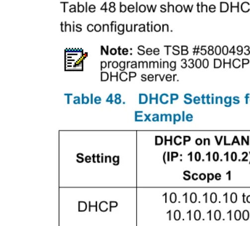
One DHCP per VLAN . . . 217
DHCP Server Settings for One DHCP per VLAN Example . . 217
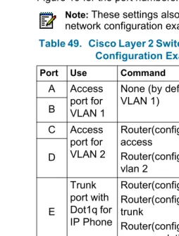
Layer 2 Switch Settings Example . . . 219
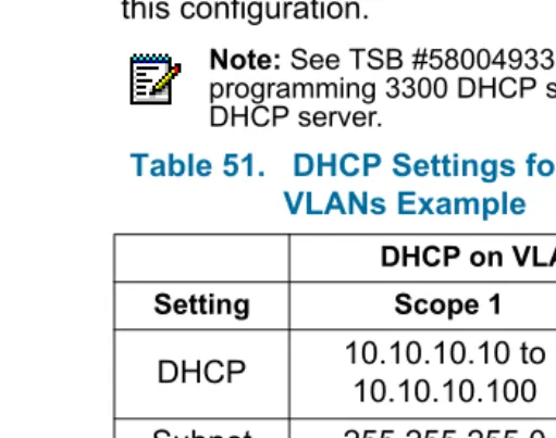
One DHCP for Two VLANs . . . 220
DHCP Server Settings for One DHCP for Two VLANs Example . . . 220
Layer 2 Switch Settings Example . . . 221
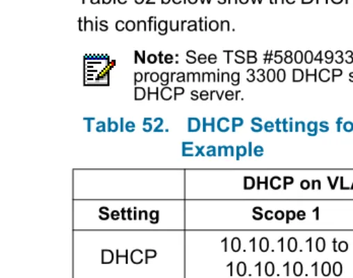
Router on a Stick. . . 222
DHCP Server Settings for One DHCP for Two VLANs Example . . . 222
Layer 2 Switch Settings Example . . . 223
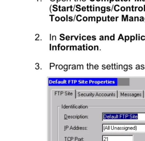
Windows 2000 FTP Server . . . 224
Appendix C :
Installation Planner
About This Appendix . . . 234
Installation Planner . . . 234
Appendix D :
Hardware Reference
About This Appendix . . . 239System Configurations . . . 239
Hardware Equipment Details. . . 241
Controller . . . 241
Controller Components . . . 242
Controller Cabinets . . . 242
Controller Alarm Port Pinout . . . 243
Network Service Units . . . 243
Universal/R2 NSU . . . 243
BRI NSU . . . 243
Analog Service Unit . . . 244
Peripheral Unit . . . 244
Fiber Interface Module . . . 245
DID Loop/Tie Trunk Card . . . 246
DNI Line Card . . . 246
DTMF Receiver Card . . . 247
E&M Trunk Card . . . 247
SN-1 and SN-2 Cards . . . 248
LG.GS Trunk Card . . . 248
ONS CLASS/CLIP Card . . . 250
ONS Line Card . . . 250
OPS Line Card . . . 251
Digital Service Unit . . . 251
Appendix E :
Status LEDs
About This Appendix . . . 254
Controller LEDs. . . 254
FIM LEDs . . . 255
LAN Ethernet Ports LEDs . . . 255
CIM LEDs. . . 256
Alarm LEDs . . . 257
Universal/R2 NSU LEDs . . . 258
LAN LEDs . . . 259
L0/L1 LEDs . . . 260
Card Status LEDs . . . 261
NSU FIM LEDs . . . 262
NSU CIM LEDs . . . 262
BRI NSU LEDs . . . 263
BRI Circuit LEDs . . . 263
CEPT LED . . . 263
ASU LEDs . . . 264
CIM LED . . . 264
ONS Circuit LEDs . . . 265
LS Circuit LEDs . . . 265
Peripheral Unit LEDs. . . 266
Fiber Interface Module LEDs . . . 266
DSU LEDs. . . 267
DSU PRI Card LEDs . . . 267
R2 Card LEDs . . . 269
Appendix F :
FRU Part Numbers
FRU Part Numbers . . . 272Hardware FRU Part Numbers . . . 272
Software Options FRU Part Numbers . . . 277
Appendix G :
Handling Fiber Optic Cables
Handling Fiber Optic Cables . . . 284List of Figures
Figure 1. Example of a 3300 ICP System . . . 5
Figure 2. Slots Location for 100-User System. . . 15
Figure 3. Slots Location for 250- and 700-User Systems . . . . 16
Figure 4. Installing the Controller Hard Drive . . . 17
Figure 5. Programming the License/Option Keys . . . 21
Figure 6. Peripheral Unit AC Power Cord Access . . . 50
Figure 7. Peripheral Unit Backplane Connector Arrangements53 Figure 8. Peripheral Unit Backplane Wiring. . . 54
Figure 9. installing the BRI Interface Assembly. . . 68
Figure 10. Connecting the Terminal Equipment to the BRI Card69 Figure 11. Installing a Peripheral Resource Card . . . 76
Figure 12. Setting R2 Card Termination Impedance . . . 78
Figure 13. Slots Location for 100-User System. . . 87
Figure 14. Slots Location for 250- and 700-User Systems . . . . 87
Figure 15. Replacing the Controller Hard Drive. . . 113
Figure 16. Peripheral Node Power Converter Connections . . 120
Figure 17. Installing the BRI Interface Assembly. . . 125
Figure 18. Setting R2 Card Termination Impedance . . . 128
Figure 19. One DHCP per VLAN Example . . . 217
Figure 20. One DHCP for Two VLANs Example . . . 220
Figure 21. Router on a Stick Example. . . 222
Figure 22. Windows 2000 FTP - FTP Site Tab . . . 224
Figure 23. Windows 2000 FTP - Security Accounts Tab. . . 225
Figure 24. Windows 2000 FTP - Home Directory Tab. . . 225
Figure 25. 100-User Controller Slot Numbering Convention . . 240
Figure 26. 250- and 700-User Controllers Slot Numbering Convention . . . 240
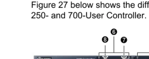
Figure 27. 250-/700-User Controller Components . . . 242
Figure 28. Universal NSU . . . 243
Figure 30. BRI NSU . . . 243
Figure 31. Universal ASU . . . 244
Figure 32. ASU . . . 244
Figure 33. Peripheral Unit FIM . . . 245
Figure 34. DID Loop/Tie Trunk Card. . . 246
Figure 35. DNI Line Card . . . 246
Figure 36. DTMF Receiver Card. . . 247
Figure 37. E&M Trunk Card . . . 247
Figure 38. SN21 and SN-2 Cards . . . 248
Figure 39. LG/GS Trunk Card. . . 248
Figure 40. LG/GS Trunk Card Power Distribution. . . 249
Figure 41. LG/GS Trunk Card Termination Types . . . 249
Figure 42. ONS CLASS/CLIP Card . . . 250
Figure 43. ONS Line Card . . . 250
Figure 44. OPS Line Card. . . 251
Figure 45. Conference Card . . . 252
Figure 46. Controller LEDs . . . 254
Figure 47. Controller LAN Ethernet Port LEDs . . . 255
Figure 48. Controller CIM LEDs . . . 256
Figure 49. Alarm LEDs . . . 257
Figure 50. Universal and R2 NSU LEDs. . . 258
Figure 51. BRI NSU LEDs . . . 263
Figure 52. Universal ASU LEDs . . . 264
Figure 53. ASU LEDs . . . 264
Figure 54. FIM LEDs. . . 266
Figure 55. DSU PRI Card LEDs . . . 267
List of Tables
Table 1. 3300 Controller Versions . . . 16
Table 2. Installing DSP Modules . . . 19
Table 3. PC-to-Controller Serial Settings . . . 20
Table 4. PC-to-Controller Ethernet Settings. . . 20
Table 5. VxWorks Settings . . . 24
Table 6. E2T Static IP Address Programming . . . 25
Table 7. IP Address Range (Scope) Programming . . . 26
Table 8. Mitel DHCP Options . . . 26
Table 9. NSU L0/L1 DIP Switch Settings . . . 32
Table 10. NSU Pinouts for Line/Network Termination . . . 32
Table 11. CIM Connector Pinout (Controller, NSU & ASU) . . . 33
Table 12. NSU Trunk Type Programming Information . . . 33
Table 13. PC-to-BRI NSU Serial Settings . . . 34
Table 14. BRI Connector Pinout (Amphenol 25-pin) . . . 35
Table 15. Direct Connection Driver Settings for Windows 95/98 . . . 37
Table 16. ASU 25-Pair D-Type Connector Pinout . . . 46
Table 17. Universal ASU Music on Hold Connector Pinout . . . 47
Table 18. Universal ASU Pager Connector Pinout. . . 47
Table 19. Card Slots 1, 4, 7 and 10 Connections to Cross-Connect Field . . . 56
Table 20. Card Slots 2, 5, 8 and 11 Connections to Cross-Connect Field . . . 57
Table 21. Card Slots 3, 6, 9 and 12 Connections to Cross-Connect Field . . . 58
Table 22. Peripheral Unit Programming Settings . . . 59
Table 23. DS1 DB-15 Connector Pinout . . . 71
Table 24. DS1 Pinouts for Line/Network Termination . . . 71
Table 25. R2 Card RJ-45 Connector Pinout. . . 79
Table 26. Peripheral Unit Programming Settings . . . 79
Table 28. 3300 Controller Versions . . . 87
Table 29. Voice Mail Upgrade Preconditions. . . 89
Table 30. Installing a DSP Module for Voice Mail Ports . . . 90
Table 31. Compression Channels Upgrade Preconditions . . . 92
Table 32. Installing Compression DSP Module(s) . . . 93
Table 33. 250- to 700-User Upgrade Preconditions . . . 94
Table 34. Upgrading a 250-User System to 700 Users . . . 94
Table 35. VxWorks Settings . . . 104
Table 36. Debug Cable E2T VxWorks Settings. . . 135
Table 37. Troubleshooting Tools . . . 140
Table 38. Troubleshoot ESM . . . 146
Table 39. Troubleshoot Software Installation and Upgrade. . 148
Table 40. Troubleshoot Software Backup and Restore . . . 152
Table 41. Troubleshoot Alarms . . . 159
Table 42. Troubleshoot the NSU . . . 161
Table 43. Troubleshooting IP Trunks. . . 170
Table 44. Troubleshoot IP Phone Registration Problems . . . 172
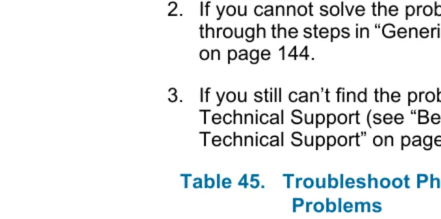
Table 45. Troubleshoot Phone Connection Problems . . . 182
Table 46. Troubleshoot Audio Quality Problems . . . 186
Table 47. Troubleshoot IP Console Problems . . . 190
Table 48. DHCP Settings for One DHCP per VLAN Example 218 Table 49. Cisco Layer 2 Switch Settings for Network Configuration Examples. . . 219
Table 50. HP Layer 2 Switch Settings for Typical Configurations . . . 219
Table 51. DHCP Settings for One DHCP for Two VLANs Example. . . 221
Table 52. DHCP Settings for Router on a Stick Example . . . 223
Table 53. Maximum Hardware Capacity . . . 229
Table 54. Maximum Software Feature Capacity . . . 231
Table 55. System Administration Tool Settings . . . 234
Table 58. IP Phone Settings. . . 236
Table 59. Set Programming Settings . . . 236
Table 60. 3300 Controller Versions . . . 241
Table 61. Controller Alarm Port Pinout. . . 243
Table 62. CEPT Port DIP Switch Settings . . . 244
Table 63. FIM LEDs . . . 255
Table 64. Controller Ethernet Ports LEDs . . . 256
Table 65. Controller CIM LEDs . . . 256
Table 66. Controller Alarm LEDs . . . 257
Table 67. NSU LAN LEDs . . . 259
Table 68. NSU L0/L1 LEDs . . . 260
Table 69. NSU Card Status LEDs . . . 261
Table 70. NSU FIM LEDs. . . 262
Table 71. NSU CIM LEDs . . . 262
Table 72. CEPT LED . . . 263
Table 73. ASU CIM LED . . . 264
Table 74. ASU ONS Circuit LEDs . . . 265
Table 75. Universal ASU LS Circuit LEDs . . . 265
Table 76. DSU PRI Card Circuit LEDs . . . 267
Table 77. DSU R2 Card Circuit LEDs . . . 269
Table 78. Hardware FRU Part Numbers . . . 272
About This Handbook
Purpose
The 3300 ICP Technician’s Handbook provides instructions on installing, upgrading, maintaining and troubleshooting the Mitel Networks™ 3300 Integrated Communications Platform (ICP).
Audience
This handbook is aimed for certified 3300 ICP technicians.
Contents
This handbook is organized as follows:
• Chapter 1: Introduction
• Chapter 2: Installation (page 11)
• Chapter 3: Upgrade and FRUs (page 83)
• Chapter 4: Programming (page 129)
• Chapter 5: Troubleshooting (page 137)
• Chapter 6: Maintenance (page 193)
• Appendix A: Typical Network Configurations (page 215)
• Appendix B: System Capacity (page 227)
• Appendix C: Installation Planner (page 233)
• Appendix D: Hardware Reference (page 237)
• Appendix E: Status LEDs (page 253)
• Appendix F: FRU Part Numbers (page 271)
Symbols Used in this Handbook
Important Safety Instructions
CAUTION: Failure to follow all instructions may
result in improper equipment operation and/or risk of electrical shock. See the 3300 Safety Instructions on Mitel Online for complete safety information.
Note: Used to provide additional information you should know about a topic.
Tip: Used to give advice on a topic.
Time: Used to indicate the time it takes to complete a procedure.
About the 3300 ICP
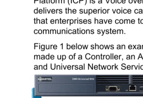
The Mitel Networks™ 3300 Integrated Communications Platform (ICP) is a Voice over IP (VoIP) solution that delivers the superior voice capabilities and the features that enterprises have come to expect from a
communications system.
Figure 1 below shows an example of a 3300 ICP system made up of a Controller, an Analog Services Unit (ASU) and Universal Network Services Unit (NSU).
Figure 1. Example of a 3300 ICP System
For additional information, see the following chapters:
• Appendix B: System Capacity (page 227)
• Appendix D: Hardware Reference (page 237)
Network Configurations
The most common configurations of the 3300 ICP in a network are:
• One DHCP per VLAN
• One DHCP for two VLANs
• One router interface to multiple VLANs (router on a stick)
Software Tools
The system has a number of programming tools that have been designed for different levels of user:
• The System Administration Tool (also known as
ESM) provides a Web-based interface that trained technicians use to program the system.
• The Group Administration Tool provides a
Web-based interface that enables administrators and receptionists to make changes to user information.
• The Desktop Tool provides a Web-based interface that enables IP telephone users to program their telephone feature keys on their phone.
• The Configuration Tool enables the installer to get a new system up and running at the installation site. It also enables databases from legacy SX-2000 Light, SX-2000 MicroLight systems, 3200 ICP systems, and 3800 WAG systems to migrate to the 3300 ICP through a database conversion and restoration utility.
• The ISDN Maintenance and Administration Tool
Additional Documentation
About the 3300 ICP Documentation
The 3300 ICP documentation set includes the following components:
• Printed documents.
• PDF Documents on Mitel Online (including copies of the printed documents).
• Customizable Manual Maker guides on Mitel Online.
• Online Help.
In addition, you can get the following technical documents from Mitel Online:
• Field Change Instructions (FCI): describes software changes, bug fixes, outstanding issues and hardware compatibility considerations for each software release. The FCI is also included on the 3300 ICP software CD-ROM.
Getting 3300 ICP Documentation
Access Online Help
• In the software application (System Administration Tool, IMAT, etc.), click the Help link or button to access the tool’s Online Help.
Access Mitel Online
1. From a web browser, go to www.mitel.com.
2. In the Global Online Services pull-down menu (near top center of screen), select Mitel Online (Global).
3. Enter your Mitel Online username and password, and click Login.
Get 3300 ICP documentation on Mitel Online
1. Access Mitel Online.
2. Move your cursor on Downloads (left side of screen), and select Product Documentation.
3. To view a document: click on the name of the desired document.
4. To download a document:
• Right-click the name of the desired document, and select Save Target As…. OR
• When viewing a PDF document, click on the disk icon.
Get User and Installation Guides on Mitel Online
1. Access Mitel Online.
2. Move your cursor on Downloads (left side of screen), and select Product Documentation.
3. Click on Installation Guides (for Installation Guides) or User Guides (for other documents).
4. To view a document: click on the name of the desired document.
5. To download a document:
• Right-click the name of the desired document, and select Save Target As…. OR
• When viewing a PDF document, click on the disk icon.
Create telephone User Guides with Manual Maker
1. Access Mitel Online.
2. Move your cursor on Downloads (left side of screen), and select Product Documentation.
3. Click on Manual Maker.
Contacting Mitel
Sending Us Feedback
If you have suggestions on how to improve this documentation, please contact us at
Contacting Mitel Networks
Contact Mitel Networks Order Desk
You can reach the Order Desk at 1-800-796-4835.
Contact Mitel Networks Repair Department
You must get a Return of Merchandise Authorization (RMA) form from the Repairs Department before sending equipment back to Mitel Network.
You can reach the Repairs Department at 1-888-222-6483.
Contact Technical Support
Please contact Mitel Technical Support if you require technical assistance.
IMPORTANT:
Before calling Mitel Technical Support, please go through the applicable section(s) of the Troubleshooting chapter (page 137).
If you cannot find the source of the problem in the Troubleshooting chapter, please collect the required information listed in the applicable section(s) of the Troubleshooting chapter before calling Mitel Technical Support.
About This Chapter
This chapter contains instructions on installing a 3300 ICP. For information on upgrading and replacing the 3300 ICP equipment, see Chapter 3 on page 83.
Installation Overview
This section contains a brief overview of the steps required to install and configure (program) a 3300 ICP system. Install the system in the order shown (bullets indicate steps that may or may not be needed, depending on the configuration of the system).
1. Installing the Controller (page 14):
a. Installing the Controller Hardware (page 15). b. Connecting the Controller to the Network
(page 23).
2. Installing Service Units (page 29):
• Installing 3300 Network Service Units (page 29) • Installing 3300 Analog Service Units (page 44) • Installing Peripheral Units (page 48)
• Installing SUPERSET HUBs (page 60) • Installing Digital Service Units (page 63)
3. Installing Phones and Peripherals (page 29)
4. Programming Voice Mail (page 80)
5. Saving the Settings (page 29)
Note: Before installing a 3300 ICP, always read the Field Change Instructions (FCI) for the software you are installing. The FCI describes software changes, bug fixes, outstanding issues and hardware
Installing the Controller
This section contains detailed instructions on installing and configuring the 3300 ICP Controller.
Overview
Installing the Controller Hardware (page 15):
1. Install the Controller Hard Drive (page 17).
2. Install the System ID Module (page 18).
3. Install the DSP Module(s), if required (page 19).
4. Connect the Maintenance PC to the Controller (page 20).
5. Turn on the Controller (page 20).
6. Verify the Connections (page 21).
7. Program the License and Option Keys (page 21).
Connecting the Controller to the Network (page 23):
1. Set the Controller RTC IP address (below).
2. Program the Controller DHCP settings. (page 25)
3. Verify the Operation of the Controller (page 27).
The Maintenance PC
The Maintenance PC is used to program and
troubleshoot the 3300 Controller and Service Units, as well as the phones and peripherals connected to the 3300 ICP. You can use a desktop computer or a laptop as Maintenance PC.
The Maintenance PC must meet the following requirements:
• Windows 95, 98, NT or 2000 Professional
• Internet Explorer 5.5 with Service Pack 2 or later, and 128-but encryption
• a VT-100 emulator program
• a Network Interface Card (NIC)
• an FTP server (such as Microsoft IIS)
• 500 MB of free disk space
Installing the Controller Hardware
About the 3300 Controller
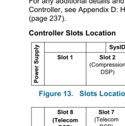
For any additional details and information on the Controller, see Appendix D: Hardware Reference (page 237).
Controller Slots Location
Figure 2. Slots Location for 100-User System
Po
w
er Su
pp
ly SysID
Slot 1 Slot 2
(Compression DSP)
Slot 3
(Telecom/ Compression
DSP)
Slot 4
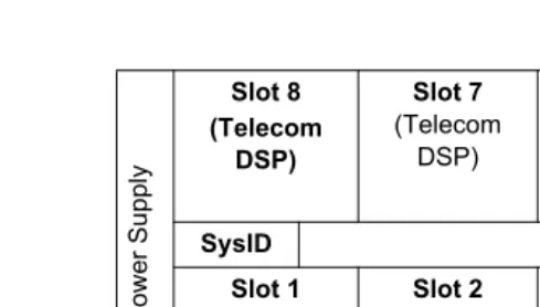
Figure 3. Slots Location for 250- and 700-User Systems
Controller Part Numbers
Table 1 below shows the part numbers for the various versions of Controllers you may encounter:
Pow
er Supply
Slot 8 (Telecom
DSP)
Slot 7
(Telecom DSP)
Slot 6
(Echo Canceller)
Slot 5
(Echo Canceller)
SysID Slot 1
(FIM)
Slot 2
(FIM)
Slot 3
(Compression DSP)
Slot 4
(Compression DSP)
Table 1. 3300 Controller Versions
Speed 100-User 250-User 700-User
133 MHz n/a 50001262 50001263
300 MHz 50002211 50002970 50002971
Note: The 133 MHz Controller part numbers shown are for North America only.
Install the Controller Hard Drive
Figure 4. Installing the Controller Hard Drive
1. Remove the Controller from its packaging.
2. Remove the Hard Drive from its packaging.
3. Locate the Hard Drive ribbon cable and power cable in the Controller hard drive enclosure (see Figure 4 above).
4. Connect the cables in step 3 to the corresponding connectors on the Hard Drive.
5. Insert the Hard Drive as shown in Figure 4 above.
6. Secure the Hard Drive plate to the Controller using the screws provided with the Hard Drive.
Next: Go to “Install the System ID Module” below. Power Cable
Install the System ID Module
1. Remove the System ID Module from its packaging.
2. Remove the bottom cover of the Controller (see “Removing/Installing the Controller Cover” on page 110).
3. Remove the protective cover from the System ID Module’s connector.
4. Slide the System ID Module between the slots indicated below, and insert the module connector in its mate on the Controller.
• 100-User Controller: slots 1 and 2 (see Figure 2 on page 15).
• 250- and 700-User Controllers: slots 1 and 8 (see Figure 3 on page 16).
5. Secure the System ID Module using the screw provided with the module.
6. If you are not installing DSP Compression Modules, put the Controller’s bottom cover back on (see “Removing/Installing the Controller Cover” on page 110).
Next:
• If you are installing a DSP Compression Module, go to “Install the DSP Module(s)” below.
• If you are not installing DSP Compression Modules, go to “Connect the Maintenance PC to the
Install the DSP Module(s)
Perform this step if the system needs compression channels and/or 30 voice mail ports (see Appendix F on page 271 for the part numbers of the DSP Modules):
• For 30 voice mail ports, add one (1) DSP Module (does not apply to 700-user Controller).
• For 32 channels compression, install one (1) DSP Module.
• For 64 channels compression, install two (2) DSP Modules (does not apply to the 100-user Controller).
Repeat the steps below for each DSP Module you install:
1. Remove the DSP Module from its packaging.
2. Remove the blank module cover at the front of the Controller, and insert the DSP Module in the
appropriate slot (see Table 2 below, Figure 2 on page 15 and Figure 3 on page 16).
3. Secure the DSP Module to the Controller using the screws provided with the module.
4. Put the Controller’s top cover back on, and secure it with its screws (see “Removing/Installing the Controller Cover” on page 110 for more information).
Next: Go to “Connect the Maintenance PC to the Controller” below.
Note: Make sure you have the appropriate compression license before installing DSP Modules for compression.
Table 2. Installing DSP Modules
Feature 100-User System
250-User System
700-User System
30 VM ports Slot 3 Slot 7 n/a
32 Comp. Channels
20 VM Ports Slot 3
Slot 3 Slot 3
30 VM Ports Slot 2
Connect the Maintenance PC to the Controller
1. Connect an RS-232 straight DTE serial cable between the Controller’s Maintenance port and the PC’s serial port.
2. Program the PC’s serial port (from the
communication program) with the following settings:
3. Connect a straight-through Ethernet cable (RJ-45 connectors) between the Controller’s leftmost Ethernet Port and the PC’s Network Interface Card (NIC).
4. Program the PC’s Network Interface Card (NIC) with the following settings:
Next: Go to “Turn on the Controller” below.
Turn on the Controller
1. Connect the female end of the power cable to the Controller, and secure it with the latch.
2. Connect the other end of the power cable to a protected outlet. The Controller turns on.
Next: Go to “Verify the Connections” below.
Table 3. PC-to-Controller Serial Settings
Baud Rate 9600 Stop Bits 1
Data bits 8 Flow Control None
Parity None
Table 4. PC-to-Controller Ethernet Settings
PC IP Address 192.168.1.n (where n is a value between 30 and 254)
PC Subnet Mask 255.255.255.0
Verify the Connections
Perform the steps below to verify the connections between the Maintenance PC and the Controller.
1. To verify the serial connection:
a. In the VT-100 emulator, press RETURN. b. If the serial connection is installed and
programmed properly, a right-pointing arrow (→) is displayed when you press ENTER.
2. To verify the Ethernet connection:
a. From the PC, PING the Controller’s RTC IP address (default is 192.168.1.2).
b. If the Ethernet connection is installed and programmed correctly, the Controller replies to the PING.
Next: Go to “Program the License and Option Keys” below.
Program the License and Option Keys
1. From the Maintenance PC, start Internet Explorer.
2. Open the System Administration Tool:
a. Enter the Controller’s IP address in the Address
field of Internet Explorer, and press ENTER (default IP address is 192.168.1.2).
b. Enter the ESM login username and password, and click the OK button.
c. Click the System Administration Tool button. The System Administration Tool opens.
3. In the Selection: drop-down menu on the left (when it says [Click Here to Start]), select System Configuration.
4. Click on the System Capacity folder, then on the
License and Option Selection form.
5. Click the Change button, and fill-in the fields as required (see your Mitel Options sheet). For more information, click the Help button to access the System Administration Tool’s Online Help.
6. Enter the Mitel Options Password (MOP) in the
Password field, then click the Save button.
7. Reboot the Controller (press the Reset button on the Controller).
Next: Go to “Connecting the Controller to the Network” below.
Note: The default login username and password are system and password, respectively. To prevent security problems, change these as soon as possible (System Access Authorization form in ESM).
Note: In the Configuration Options section, we recommend that you enable Networking Option and Mitai/Tapi Computer Integration.
Connecting the Controller to the Network
This section assumes that the network is already set up, and that there is a serial connection between the Maintenance PC and the Controller (see “Connect the Maintenance PC to the Controller” on page 20).
Overview
1. Set the Controller RTC IP address (page 23).
2. Program the Controller DHCP settings. (page 25)
3. Verify the Operation of the Controller (page 27).
4. Configure the Layer 2 switch (page 28).
Set the Controller RTC IP address
1. Start the communication program on the PC.
2. Press the Reset button on the Controller (use a small non-metallic pointed object).
3. When the communication program displays Press any key to stop auto-boot, press a key.
4. When [VxWorks Boot]: is displayed, type c and press ENTER.
5. Go through the VxWorks settings (see Table 5 below). For each setting shown in bold, enter a value, then press ENTER. For all other settings, press ENTER to accept the default value.
Note: The Maintenance PC must be on the same subnet as the Controller.
6. Press the Reset button on the Controller.The Controller restarts.
7. Remove the serial connection between the Controller
Table 5. VxWorks Settings
Prompt Value Note
boot device ata=0, 0 Boot device is Disk.
processor number 0 Not used.
host name bootHost
file name /sysro/Rtc8260 Boot location and file name.
inet on ethernet (e) IP address and subnet mask (hex) for Controller RTC (for example, 134.199.63.11:ffffff00). Obtain it from your IT administrator.
inet on backplane (b)
host inet (h) IP address of PC. Used for
software upgrades.
gateway inet (g) IP address of the end user’s default gateway for the 3300 ICP (must be outside the DHCP range).
user (u) ftp
ftp password (ftp) ftp
flags (f) 0x0 Fixed IP address (0x40 used
on E2T for DHCP). target name (n)
startup script (s)
other (o) motfcc Other device, E2T using
Network boot from.
Next: Go to “Program the Controller DHCP settings.” below.
Program the Controller DHCP settings.
1. On the PC, go to ESM and open the System Administration Tool.
2. In the System Administration section, open the
DHCP folder.
3. In the DHCP Subnet form, enter the subnet name, IP address and bit mask.
4. In the DHCP Static IP form, program a static IP address for the E2T using the information in Table 6 below (skip this step for the 100-user Controller).
Table 6. E2T Static IP Address Programming
Option ID Value Notes/Example
Name Name of E2T
Subnet Subnet of E2T Select subnet.
IP Address IP address of E2T 162.168.1.5
Protocol “BOOT or DHCP”
Hardware Address:
Type MAC Address
Other - Type n/a
Address MAC address of
Controller (found on back)
00:12:3a:4b: c5:67
Other - Address Length
n/a
5. In the DHCP IP Address Range form, program the scope using the information in Table 7 below.
6. In the DHCP Options form, program the options listed in Table 8 below for the scope you just programmed.
Note: The following IP addresses are reserved for the ASUs:
192.168.10.1 to 192.168.10.3 192.168.11.1 to 192.168.11.3 192.168.12.1 to 192.168.12.3 192.168.13.1 to 192.168.13.3
Table 7. IP Address Range (Scope) Programming
Option ID Value Notes/Example
Name of the range
Subnet Select subnet.
IP Range Starta Start of scope 192.168.1.15
IP Range Enda End of scope 192.168.1.25
Protocol “BOOT or DHCP”
Client’s class ID must match name
Clear checkbox.
Lease Time 2 Weeks
a. Cannot be modified once form is saved.
Table 8. Mitel DHCP Options
Option ID Value Notes/Example
128 Usually the Controller IP
Address
168.192.1.2
129 Usually the Controller
RTC IP Address
168.192.1.3
130 MITEL IP PHONE
132 VLAN ID (optional) 2
7. In the DHCP Server form, enable the Controller’s internal DHCP server.
Next: Go to “Verify the Operation of the Controller” below.
Verify the Operation of the Controller
This procedure verifies that the Controller is operating correctly before connecting it to the network.
1. On the PC, go to ESM and open the System Administration Tool.
2. In the Maintenance and Diagnostics section, open the System Hardware Profile folder, and verify the information in the forms is correct, including the IP address of the E2T.
3. In the Maintenance and Diagnostics section, open the Alarm Details form.
4. Verify that the following alarms do not appear (if you get an alarm, go to “Troubleshooting Alarms” on page 159):
• E2T Com • DSP
The following steps are optional:
5. Connect two IP Phones directly to one of the Controller’s Ethernet ports (for a 100-user Controller, you must use a Layer 2 switch for these steps).
6. Program the IP Phones (see the System Administration Tool Online Help for details).
7. Make a call from one phone to the other, and verify that the alarms in Step 4 above do not appear in the
Alarm Details form.
8. Remove the IP Phones from the Controller.
Configure the Layer 2 switch
The 3300 ICP requires a Layer 2 switch between its Controller and the network.
1. Connect an Ethernet cable between the Layer 2 switch on your network and the leftmost available Ethernet port on the 3300 Controller.
If you are installing a 100-user system, move the PC Ethernet connection from the Controller to one of the Layer 2 switch input ports, and connect the Layer 2 switch to the leftmost Ethernet port of the Controller.
2. Program the Layer 2 switch with the appropriate settings (see Appendix A on page 215 for examples).
See your IT administrator for information on setting up and programming a DHCP server. We
recommend that you only use the Controller’s internal DHCP server to provide a static IP address to the E2T, and an external DHCP server for all other equipment.
3. If you are not using the Controller’s DHCP server, disable the Controller’s DHCP server in the DHCP Server form (System Administration section,
DHCP folder). OR
Next: Go to “Installing Service Units” below.
Note: You can do the same for a 250- and a 700-user system, if desired.
Note: Typically, access ports are used to connect the Layer 2 switch to the Controller, and trunk ports to connect the Layer 2 switch to the IP Phones.
Note: See TSB #58004933 for information on
Installing Service Units
This section contains detailed information on installing Service Units and other adjunct equipment of the 3300 ICP.
Overview
Install the Service Units required for your system. See the appropriate sections for details.
• Installing 3300 Network Service Units (page 29)
• Installing 3300 Analog Service Units (page 44)
• Installing Peripheral Units (page 48)
• Installing SUPERSET HUBs (page 60)
• Installing Digital Service Units (page 63)
Next: Go to ““Installing Phones and Peripherals” on page 80”.
Installing 3300 Network Service Units
You can install any of the following Network Service Units (NSUs):
• NSU (MSDN, PRI/QSIG, T1D4)
• R2 NSU
• BRI NSU
You can double the number of NSUs in a system by chaining secondary NSUs to the (primary) NSUs connected to the Controller (one secondary NSU per primary NSU). BRI NSUs cannot be chained.
Install an NSU
The steps below apply to all NSUs, except the BRI NSU. See “Install a BRI NSU” on page 34 for information on installing a BRI NSU.
1. Mount and secure the NSU in the desired location.
2. Set the L0/L1 port DIP switches to the appropriate termination mode and impedance (see Table 9 and Table 10 on page 32). The default is network termination mode. See Appendix D on page 237 for the location of these switches.
3. Set the Message Link DIP switch to the appropriate position. See Appendix D on page 237 for the location of the Message Link switch.
• For a primary NSU (connected directly to the Controller), set the switch to 1 (up).
• For a secondary NSU (connected to another NSU), set the switch to 2 (down).
4. Connect a fiber optic cable between the NSU FIM and the Controller FIM.
If you are installing a Secondary NSU, connect a crossover CAT5 cable between CIM 1 of the secondary NSU and CIM 2 of the primary NSU (see Table 11 on page 33 for CIM pinout).
5. Connect the NSU L0 and/or L1 port to the remote system (the PSTN or another system). See Table 10 on page 32 for the pinout.
6. For the PRI/QSIG R2 NSUs:
a. Connect the Maintenance PC to the NSU (for Windows 95/98, see page 36; For Windows 2000, see page 40).
7. Connect power to the NSU.
8. Using ESM, program the NSU settings on the Controller:
a. Program the Network Services Unit Configuration form (System Configuration
section, Units/Modules folder). See the Online Help for more information.
b. Program the following forms in the Digital Trunk
folder (System Configuration section, Trunks
folder). See Table 12 on page 33 and the Online Help for more information.
• Link Descriptor Assignment • Digital Link Assignment
• MSDN-DPNSS-DASSII Trunk Circuit Descriptor Assignment
9. For the PRI/QSIG R2 NSUs, program the NSU using IMAT (see “To Start IMAT” on page 43). See the IMAT Online Help for more information.
Next: Install any other required Service Unit (see “Overview” on page 29). If all the Service Units are installed, go to “Installing Phones and Peripherals” on page 80.
Note: The unit will be in an abnormal operation mode until all the programming is complete.
Table 9. NSU L0/L1 DIP Switch Settings
DIP
Switch Function Settings Notes
1 Tx Ground Down: Ground
Up: Floating Set to up.
2 Rx Ground Down: Ground
Up: Floating Set to up.
3
E1 Twisted Pair cable selector (RJ-45, PRI)
Down: Enabled Up: Disabled
120 ohm impedance
4 T1 cable selector (T1/D4) Down: Enabled Up: Disabled
100 ohm impedance
5 E1, co-ax cable selector (R2) Down: Enabled Up: Disabled
75 ohm impedance
6
Line/Network Termination selector
Down: Line Up: Network
Table 10. NSU Pinouts for Line/Network Termination
Pin Termination ModeLine Termination ModeNetwork
1 Tx Ring Rx Ring
2 Tx Tip Rx Tip
3 Unused Unused
4 Rx Ring Tx Ring
5 Rx Tip Tx Tip
6 Unused Unused
7 Unused Unused
Table 11. CIM Connector Pinout (Controller, NSU & ASU)
Pin Signal Pin Signal
1 RX+ 5 Not used
2 RX- 6
TX-3 TX+ 7 Not used
4 Not used 8 Not used
Table 12. NSU Trunk Type Programming Information
NSU Protocol (Integrated Access)Link Descriptor MSDN Trunk Circuit Descriptor Type
Universal
T1/E1 T1/E1 PRI/QSIG ISDN Node
Universal T1 Universal E1
Universal
T1 T1 E&M T1D4 Universal T1
Universal
T1/E1 T1/E1 MSDN DPNSS
Universal T1 Universal E1
Install a BRI NSU
The BRI NSU is connected to the Controller via a Universal NSU.
To install a BRI NSU
The BRI NSU connects to a Universal E1 MSDN NSU.
1. Mount the BRI NSU.
2. Connect the BRI NSU L0/L1 ports to the Universal NSU L0/L1 ports (Table 9 and Table 10 on page 32).
3. Connect the BRI NSU to the remote system (the PSTN or another system). See Table 14 on page 35 for the pinout.
4. Connect the BRI NSU to the Maintenance PC: a. Connect the RS-232 port (RJ-45 connector) on the
BRI NSU to a serial port on the Maintenance PC. b. Set up the communications program on COM port
1 or 2 with the following parameters:
5. Power up the BRI NSU.
6. On the Maintenance PC, program the BRI NSU using the VT-100 emulator. See TSB #58004741 for more information.
Note: Ensure the Universal E1 NSU is programmed before connecting the BRI NSU to it.
Note: A Category 5 connection from the 3300 BRI NSU E1 port to a 3300 Universal NSU that is running E1 DPNSS. E1 connections as TX and RX pairs in RJ-45. Option to ground one side of TX and or RX (using DIP switch) to use with coax adapter.
Table 13. PC-to-BRI NSU Serial Settings
Baud Rate 9600 Stop Bits 1
Data bits 8 Flow Control None
Next: Install any other required Service Unit (see “Overview” on page 29). If all the Service Units are installed, go to “Installing Phones and Peripherals” on page 80.
IMAT
The ISDN Maintenance and Administration Tool (IMAT) is a software tool used to program the PRI/QSIG variant Universal NSU and the R2 NSU. You can install IMAT on the Maintenance PC or on its own PC (IMAT PC).
IMAT Installation Overview
1. Install IMAT on the IMAT PC (page 36).
2. Connect the Maintenance PC to the NSU: • For Windows 95/98, see below.
• For Windows 2000, see page 40.
For information on opening and using IMAT, see page 43.
Table 14. BRI Connector Pinout (Amphenol 25-pin)
Pin Signal Pin Signal Pin Signal
1 T0 6 T6 11 T10
26 R0 31 R6 36 R10
2 T1 7 T7 12 T11
27 R1 32 R7 37 R11
3 T2 8 T8 13 T12
28 R2 33 R8 38 R12
4 T4 9 T8 14 T13
29 R4 34 R8 39 R13
5 T5 10 T9 15 T14
30 R5 35 R9 40 R14
To Install IMAT
1. Close all the applications running on the Maintenance PC.
2. Insert the 3300 ICP software CD-ROM in the CD drive.
3. Open the Tools folder, then the Disk 1 folder.
4. Double click the Setup.exe file. The installation program starts. Follow the prompts to install IMAT.
To Connect a Windows 95/98 Maintenance PC to an NSU
Install a Direct Connection Device Driver on Win-dows 95/98
By default, Windows does not support a direct cable connection. You must add a device driver. Windows takes the information from a Mitel file and creates the driver called NT Direct Connection.
1. Click the Start button, select Settings, then Control Panel.
2. Double-click the Modems icon:
3. In the Modem Properties window, click Add.
4. In the Install New Modem screen, click Other.
5. Select Don't detect my modem, I will select from a list, then click Next.
6. Click Have Disk.
7. Type c:\Program Files\Mitel\Imat in the Copy manufacturer's files from field, then click OK.
9. Click Next to select the NT Direct Connection.
10. Select COM 1 or COM 2, and then click Next.
11. Click Finish.
12. In the Modem Properties window, select NT Direct Connection, then click Properties.
13. Set the following parameters:
14. Click OK and close the Control Panel window.
Connect the Maintenance PC to an NSU
15. Connect an RS-232 straight DTE serial cable between the NSU’s serial port and the PC’s serial port.
Table 15. Direct Connection Driver Settings for Windows 95/98
Setting Name Value
Maximum speed 38 400
Only connect at this speed Select
Data bits 8
Parity None
Stop bits 1
Mode Auto Answer (in Advanced
Settings).
Error control Clear if you have a direct
connect cable.
Flow Control Clear if you have a direct
connect cable.
Create a Dial-Up Network Connection on Windows 95/98
Typically, you will want to follow this procedure twice to create two Dial-up Networking connections, one for on-site direct access, and one for remote modem access.
16. Click the Start button, select Programs,
Accessories, then Dial-Up Connections.
17. Double-click Make New Connection.
18. Enter an appropriate name for the connection (for example, Direct for direct connections, Remote or a customer’s name for remote connections) and click
Next.
19. Enter an Area Code and Telephone Number and select a Country Code from the drop-down list. Click
Next.
20. Click Finish.
21. Right-click your new connection icon and click
Properties.
22. Click Configure. Ensure the fields are set as follows: • Data bits: 8
• Parity: none
For a direct connection:
• Maximum speed: 38400
• Check: only connect at this speed • Select wait for dial tone before dialing • Select cancel the call time at 60 seconds.
Note: If you are creating a direct connection, make sure NT Direct Connection is listed in the drop-down list in the Make a New Connection window.
• Click Advanced and turn off error control and flow control
For a remote connection:
• Stop bits: 1
• Click Advanced and turn on error control and select Compress data.
• Turn on flow control and select Hardware.
23. Click OK.
24. Select Server Types tab and make sure that PPP: Windows, WindowsNT3.5, Internet or PPP:Internet appears in the Type of Dial-Up Server field.
25. In the Advanced Options field, select Log onto Network and Enable software compression.
26. Make sure that only TCP/IP is selected in the
Allowed network protocols field.
27. Select the Scripting tab and enter:
• for a 3300 Universal NSU: c:\program files\mitel\ Imat\pridun.scp.
• for an R2 NSU: c:\program files\mitel\Imat \r2dun.scp.
To Connect a Windows 2000 Maintenance PC to an NSU
Install a Direct Connection Device Driver on Win-dows 2000
By default, Windows does not support a direct cable connection. You must add a device driver. Windows takes the information from a Mitel file and creates the driver called NT Direct Connection.
1. Click the Start button, select Settings, then Control Panel.
2. Double-click the Phone and Modem Options icon.
3. Select the Modem tab. Click Add.
4. Click Other on the Install New Modem screen.
5. Select Don’t detect my modem, I will select it from a list, then click Next.
6. In the Modems field, select Communications cable between two computers, then click Next.
7. Select COM 1 or COM 2, then click Next.
8. Click Finish.
9. The COM Port will be displayed in the Phone and Modem Options window, Modems tab. Select the COM Port and then click Properties.
10. From the Maximum Port Speed drop-down menu, select 38400.
11. In the Communications cable between two
computers, select the Advanced tab, and then click
Change Default Preferences.
12. From the Port speed drop-down list select 38400, and then from the Flow control list select None.
13. Select the Advanced tab. From the drop-down menus, set the fields as follows:
• Data bits: 8 • Parity: none • Stop bits: 1
14. Click OK and close the Control Panel window.
Connect the Maintenance PC to an NSU
15. Connect an RS-232 straight DTE serial cable between the NSU’s serial port and the PC’s serial port.
Create a Dial-Up Network Connection on Windows 2000
Typically, you will want to follow this procedure twice to create two Dial-up Networking connections, one for on-site direct access, and one for remote modem access.
16. Click the Start button, select Programs,
Accessories, Communications, then Dial-Up Connections.
17. Double click Make New Connection, and then click
Next.
18. Select Dial-up to the Internet, and then click Next.
19. Select I want to set up my Internet connection manually, or I want to connect through a local area network (LAN). Click Next.
20. Select I connect through a phone line and a modem, and then click Next.
21. Use the COM Port that has been configured as a NULL Modem connection: 38400, 8, none, 1.
22. In the Choose Modem box, from the drop-down list select Communications cable between 2
computers. Click Next.
23. Clear the box Use area code and dialing rules, and then click Advanced.
24. For the Connection type, select PPP (Point to Point Protocol).
25. For the Logon procedure, select Use logon script, and then click Browse. Select the appropriate script (see below), click OK, then Next.
• for PRI/QSIG: c:\program files\mitel\Imat\ pridun.scp.
• for R2: c:\program files\mitel\Imat\r2dun.scp.
26. In the Internet account logon information box, leave the username and password fields blank and then click Next.
27. Dialog boxes appear that warn you that you will not be able to connect to your Internet service provider without your user name and your password. Disregard these warnings and click Yes on these boxes to continue.
28. Enter the Connection name, and then click Next.
29. In the box to set up an Internet mail account, select
No, and then click Next.
30. De-select the option to connect to the Internet immediately, then click Finish.
31. In the Network and Dial-up Connections window, right-click on the new DUN connection, point to
Properties, then click Configure.
33. Click OK until you exit the windows.
To Start IMAT
1. Start IMAT (ignore any message about username configuration error).
2. In the File menu, select Connect to Remote Site.
3. In the Dial-Up Entry box, select the connection name you entered when creating the dial-up network connection.
• For Windows 95/98, see Step 18 on page 38. • For Windows 2000, see Step 28 on page 42.
4. Ensure that the correct option (PRI CARD, R2 CARD, etc.) is selected under Remote ISDN System.
5. Click Connect.
6. In the Connected to remote site window, click OK.
To close IMAT:
a. Save any open databases. b. In the File menu, click Exit.
Installing 3300 Analog Service Units
Install an ASU
This procedure applies to both the ASU and the Universal ASU. You can connect up to four ASUs or Universal ASUs to the Controller.
1. Mount the ASU.
2. Connect a Cross-over Category 5 cable with RJ-45 connector to the CIM port on the ASU and a free CIM port on the Controller (see Table 11 on page 33).
3. Complete telephony cabling (see Table 16 on page 46).
4. For the Universal ASU, complete the Music on Hold and Paging cabling if required (see Table 17 and Table 18 on page 47).
5. Connect power to the ASU.
Once the CIM link synchronizes, the CIM LEDs turn on. The Controller detects the ASU, and the
application software downloads and starts immediately.
Note: Ensure that there is a free CIM port on the Controller.
Note: The following IP addresses are reserved for the ASUs:
192.168.10.1 to 192.168.10.3 192.168.11.1 to 192.168.11.3 192.168.12.1 to 192.168.12.3 192.168.13.1 to 192.168.13.3
Note: The 3300 Universal ASU can be located up to 30 meters (98.4 feet) away from the 3300 Controller. The interface employs a single standard 8-pin modular jack consisting of 2 balanced signal pairs and is located on the front of the unit.
6. Using ESM, program the ASU settings on the Controller. See the System Administrator Tool Online Help for more information.
a. Program the Analog Services Unit
Configuration form (System Configuration
section, Units/Modules folder). See the Online Help for more information.
b. Program the applicable forms in the Analog Trunk folder (System Configuration section,
Trunks folder). See the Online Help for more information.
c. Universal ASU only: In the Miscellaneous Assignment form (System Configuration
section, Music on Hold folder), program the virtual circuit for the Tip/Ring pair used for Music on Hold.
d. Universal ASU only: In the Loudspeaker Paging Assignment form (System Configuration
section, Loudspeaker Paging folder), program the zone and virtual circuit for the Tip/Ring pairs used for Paging.
Next: Install any other required Service Unit (see “Overview” on page 29). If all the Service Units are installed, go to “Installing Phones and Peripherals” on page 80.
Table 16. ASU 25-Pair D-Type Connector Pinout
Pin Color Code ASU Universal ASUa
a. The LS Ring/TIP 1-n connectors are only used in specific countries. They are not used in North America.
26/1 W/BL, BL/W ONS Ring/Tip 1 ONS Ring/Tip 1 27/2 W/O, O/W ONS Ring/Tip 2 ONS Ring/Tip 2 28/3 W/G, G/W ONS Ring/Tip 3 ONS Ring/Tip 3 29/4 W/BR, BR/W ONS Ring/Tip 4 ONS Ring/Tip 4 30/5 W/S, S/W ONS Ring/Tip 5 ONS Ring/Tip 5 31/6 R/BL, BL/R ONS Ring/Tip 6 ONS Ring/Tip 6 32/7 R/O, O/R ONS Ring/Tip 7 ONS Ring/Tip 7 33/8 R/G, G/R ONS Ring/Tip 8 ONS Ring/Tip 8 34/9 R/BR, BR/R ONS Ring/Tip 9 ONS Ring/Tip 9 35/10 R/S, S/R ONS Ring/Tip 10 ONS Ring/Tip 10 36/11 BK/BL, BL/BK ONS Ring/Tip 11 ONS Ring/Tip 11 37/12 BK/O, O/BK ONS Ring/Tip 12 ONS Ring/Tip 12 38/13 BK/G, G/BK ONS Ring/Tip 13 ONS Ring/Tip 13 39/14 BK/BR, BR/BK ONS Ring/Tip 14 ONS Ring/Tip 14 40/15 BK/S, S/BK ONS Ring/Tip 15 ONS Ring/Tip 15 41/16 Y/BL, BL/Y ONS Ring/Tip 16 ONS Ring/Tip 16 42/17 Y/O, O/Y ONS Ring/Tip 17 LS Ring/Tip 1 43/18 Y/G, G/Y ONS Ring/Tip 18 LS Ring/Tip 1-1 44/19 Y/BR, BR/Y ONS Ring/Tip 19 LS Ring/Tip 2 45/20 Y/S, S/Y ONS Ring/Tip 20 LS Ring/Tip 1-2 46/21 V/BL, BL/V ONS Ring/Tip 21 LS Ring/Tip 3 47/22 V/O, O/V ONS Ring/Tip 22 LS Ring/Tip 1-3 48/23 V/G, G/V ONS Ring/Tip 23 LS Ring/Tip 4 49/24 V/BR, BR/V ONS Ring/Tip 24 LS Ring/Tip 1-4
Table 17. Universal ASU Music on Hold Connector Pinout
Pin Signal Virtual Circuita,b
1/2 Tip/Ring 1 n 1 4 1
3/6 Tip/Ring 2 n 1 4 2
4/5 Tip/Ring 3 n 1 4 3
7/8 Tip/Ring 4 n 1 4 4
a. Cabinet Shelf Slot Circuit. b. CIM 1: n = 2. CIM 2: n = 3.
Note: You only need one Tip/Ring pair to program Music on Hold. The Music on Hold port is an 8-pin connector on the back of the Universal ASU.
Table 18. Universal ASU Pager Connector Pinout
Pin Signal Zone Virtual Circuita,b
1/2 Tip/Ring 1
00 n 1 5 1
3/6 Tip/Ring 1-1
4/5 Tip/Ring 2
01 n 1 5 2
7/8 Tip/Ring 1-2
a. Cabinet Shelf Slot Circuit. b. CIM 1: n = 2. CIM 2: n = 3.
Installing Peripheral Units
Overview
1. Unpack, position, and ground the Peripheral Unit (page 48).
2. Connect the fiber cable to the node (page 49).
3. Install the power converter (page 50).
4. Install the Peripheral Interface cards (page 51).
5. Cable the node to the MDF (page 52).
6. Program the Peripheral Unit (page 59).
Next: Install any other required Service Unit (see “Overview” on page 29). If all the Service Units are installed, go to “Installing Phones and Peripherals” on page 80.
Unpack, position, and ground the Peripheral Unit
1. Remove the peripheral node from its packaging.
2. Check the contents against the packing list.
3. Visually inspect the node and attached equipment for damage. Repack and return any damaged
equipment.
4. Position the node.
Note: For information about removing and replacing the front panel of the cabinet, see “Remove/Install the Front Panel” on page 117.
5. Connect an external ground to the ground terminal on the rear panel of the peripheral cabinet. Refer to the Safety Instructions for detailed grounding
requirements.
Next: Go to “Connect the fiber cable to the node” below.
Connect the fiber cable to the node
The fiber optic cable connects the FIM in the Controller to the FIM in the Peripheral Unit.
1. Review the guidelines for handling fiber optic cable (see Appendix E on page 253).
2. Route the fiber optic cable through the cable port at the rear of the peripheral cabinet into the cabinet. Extend the fiber cable approximately 30 cm (1 ft) beyond the front of the cabinet.
3. Install a short piece of nylon spiral wrap over the cable at the point where the cable exits the rear of the cabinet.
4. Close the sliding cable port door. Ensure that the door closes on the nylon spiral-wrapped section of fiber cable.
5. Remove the plastic dust caps from the fiber optic cable and the connector ferrules on the FIM faceplate.
6. Plug the fiber connectors into the connectors on the FIM faceplate. The fiber connectors have a small key that must be aligned with a slot on the FIM
connectors. Lock each connector into position by pushing the metal collar forward and clipping it onto the FIM connector.
Install the power converter
1. At the rear of the cabinet, remove the two screws that fasten the internal AC power cord access cover plate to the backplane, and remove the cover plate (see Figure 6 below).
Figure 6. Peripheral Unit AC Power Cord Access
2. Ensure that the switch on the power converter faceplate is set to off (0).
3. Unpack and inspect the power converter. • Unpack the power converter and remove all
packing materials.
• Inspect the power converter to ensure that the unit is not dented or scratched, and that all fittings are secure.