ISSN (Print) : 2320 – 3765 ISSN (Online): 2278 – 8875
I
nternational
J
ournal of
A
dvanced
R
esearch in
E
lectrical,
E
lectronics and
I
nstrumentation
E
ngineering
(An ISO 3297: 2007 Certified Organization)
Website: www.ijareeie.com
Vol. 6, Issue 3, March 2017
IoT Based Boiler Drum Level Control
1
Gomathi Sankar A, 2Jesudass Rabinson Arasu S, 3Karthick K, 4Maris Murugan T
Erode Sengunthar Engg. College, Erode, Tamilnadu, India
ABSTRACT: The most essential unit in a process industry or power generation station is a boiler. In thermal power plant steam generation in the boiler is proportional to the power demand. Steam/Water interface exist in boiler drum and the level of water in the boiler drum is very critical criteria to be maintained. If the water level becomes too low the boiler can run dry, resulting in mechanical damage of the drum and boiler piping. If the level becomes too high, water can be carried over into steam pipe work and causes damage in downstream equipment. The data from entire plant is received and logged in DCS system for experiment and analysis. The data logging system of the plant DCS monitors multi variable and multi loop control in a plant and measures and record the process variable manipulated variable, control signal etc., of a different control process. The data logging requires huge memory for recording different variables of the plant. The measured variables stored in cloud and used in the process with the IoT technology and hence huge memory occupation in DCS is reduced. In this project we attempt to apply IoT concept in simple boiler drum level control in thermal power plant and variables which are monitored are recorded in the cloud and used efficiently.
I. INTRODUCTION
A crucial control problem in boiler control is the monitoring and controlling of water level in a boiler drum. Many industrial plants have boilers for generating process steam, and of course boilers are central to thermal power generation. The boiler drum is where water and steam are separated. Controlling its level is critical because if the level becomes too low, the boiler can run dry resulting in mechanical damage of the drum and boiler piping. If the level becomes too high, water can be carried over into the steam pipework, possibly damaging downstream equipment. The design of the boiler drum level control strategy is normally described as single-element, two-element, or three-element control. This article explains the three designs.
Any mismatch between inflow (water) and outflow (steam) will cause a continuous change in the drum level. Integrating loops are difficult to tune, and can easily become unstable if the controller’s integral time is set too short (i.e. high integral gain). The process-imposed requirement for a long integral time makes the loop slow to recover from disturbances to the drum level.
If the drum level is low, and more feedwater is added to increase it, the drum level tends to decrease first before increasing. This is because the cooler feedwater causes some of the steam in the evaporator to condense, causing the volume of water/steam to decrease, and hence the drop in drum level. Conventional feedback control has difficulty in coping with this inverse response. A control loop using high controller gain and derivative action may work well in other level applications, but it will quickly go unstable on a boiler drum level. Stability is best achieved by using a low controller gain, long integral time, and no derivative. However, these settings make the controller’s response very sluggish and not suitable for controlling a process as critical as boiler drum level.
Similar to feed flow, changes in steam flow can also cause large deviations in drum level, and could possibly trip the boiler. Changes in steam flow rate are measurable and this measurement can be used to improve level control very successfully by using a feedforward control strategy.
ISSN (Print) : 2320 – 3765 ISSN (Online): 2278 – 8875
I
nternational
J
ournal of
A
dvanced
R
esearch in
E
lectrical,
E
lectronics and
I
nstrumentation
E
ngineering
(An ISO 3297: 2007 Certified Organization)
Website: www.ijareeie.com
Vol. 6, Issue 3, March 2017
almost immediately be counteracted by similar changes in feedwater flow rate. To ensure that deviations in drum level are also used for control, the output of the drum level controller is added to the feedforward from steam flow.
The combination of drum level measurement, steam flow measurement, and feed flow measurement to control boiler drum level is called three-element control.
II. OBJECTIVE
Control the drum level to the set point.
Interaction with the combustion control system should be reduced. Boiler steam output and feedwater input wanted to be balanced properly.
Perform smooth changes of the boiler drum level for different load changes in the boiler. Compensate for feed water pressure variation without process upset or set point shift.
III. SYSTEM ANALYSIS EXISTING SYSTEM:
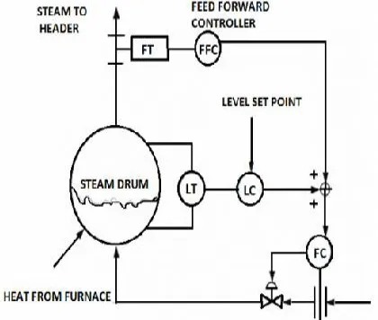
This system is basically cascade output of the two element system to the feedwater flow controller. It has three variables: Level, Steam flow rate and Feedwater flow rate which are used to manipulate the feedwater control valve. The three element drum level control is mainly suited where a boiler plant consists of multiple boilers and multiple feedwater pumps or where the feedwater has variation in pressure or flow.
Three element control assures that the signals versus feedwater flow will have a constant relationship by replacing the open flow characteristics of the feedwater control valve with a closed loop feedback control of feedwater flow.
Figure 1: 3 Element Control System.
DEMERITS:
ISSN (Print) : 2320 – 3765 ISSN (Online): 2278 – 8875
I
nternational
J
ournal of
A
dvanced
R
esearch in
E
lectrical,
E
lectronics and
I
nstrumentation
E
ngineering
(An ISO 3297: 2007 Certified Organization)
Website: www.ijareeie.com
Vol. 6, Issue 3, March 2017
PROPOSED METHOD
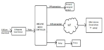
Figure 2: BLOCK DIAGRAM
In our proposed system deals with the boiler drum level controlling system. The boiler drum level is controlled by the arduino Uno microcontroller from pulse output of ultrasonic level sensor. Arduino Uno microcontroller receives the pulse signal and send to the Liquid Crystal Display (LCD) or Personal Computer (PC) with the help of the Local Area Network (LAN). Another side the same level signal send to the Internet of Things (IoT) by using Wi-Fi module. In this concept the major advantage is boiler drum level controlling, this action is taken by the Internet of Things (IoT), which means the signal from Internet of Things (IoT) connected devices like smart phones or laptops etc., From the devices the signal will be sent to the arduino Uno microcontroller for controlling the feedwater flow inside the boiler drum by relay action. Through the smart phones or laptop can store the N number of data’s, as well as control the drum level. In this system the monitoring action can also done with the help of website address.
IV. BOILER DRUM LEVEL CONTROL
.
The drum level must be controlled to the limits specified by the boiler manufacturer. If the drum level does not stay within these limits, there may be water carryover. If the level exceeds the limits, boiler water carryover into the super-heater or the turbine may cause damage resulting in extensive maintenance costs or outages of either the turbine or the boiler. If the level is low, overheating of the water wall tubes may cause tube ruptures and serious accidents, resulting in expensive repairs, downtime, and injury or death to personnel. A rupture or crack most commonly occurs where the tubes connect to the drum. Damage may be a result of numerous or repeated low drum level conditions where the water level is below the tube entry into the drum.
When the drum level gets too low, the boiler must have a boiler trip interlock to prevent damage to the tubes and cracks in the tubes where they connect to the boiler drum. The water tubes may crack or break where they connect to the drum, or the tubes may rupture resulting in an explosion. The water tube damage may also result in water leakage and create problems with the drum level control. The water leakage will affect the drum level because not all the water going into the drum is producing steam.
ISSN (Print) : 2320 – 3765 ISSN (Online): 2278 – 8875
I
nternational
J
ournal of
A
dvanced
R
esearch in
E
lectrical,
E
lectronics and
I
nstrumentation
E
ngineering
(An ISO 3297: 2007 Certified Organization)
Website: www.ijareeie.com
Vol. 6, Issue 3, March 2017
V. METHODOLOGY
A microcontroller (sometimes abbreviated µC, uC or MCU) is a small computer on a single integrated circuit containing a processor core, memory, and programmable input/output peripherals. Program memory in the form of NOR flash or OTP ROM is also often included on chip, as well as a typically small amount of RAM. Microcontrollers are designed for embedded applications, in contrast to the microprocessors used in personal computers or other general purpose applications. The proposed solutions have been designed using Xilinx. The area-efficient carry select adder can also achieve an outstanding performance in power consumption. Power consumption can be greatly saved in our proposed area-efficient carry select adder because we only need one XOR gate and one INV gate in each summation operation as well as one AND gate and one OR gate in each carry-out operation after logic simplification and sharing partial circuit. Because of hardware sharing, we can also significantly reduce the occurring chance of glitch. Besides, the improvement of power consumption can be more obvious as the input bit number increases.
A.ARDUINO MICROCONTROLLER:
Arduino is a single-board microcontroller to make using electronics in multidisciplinary projects more accessible. The hardware consists of an open-source hardware board designed around an 8-bit Atmel AVR microcontroller, or a 32-bit Atmel ARM. The software consists of a standard programming language compiler and a boot loader that executes on the microcontroller.
HARDWARE:
A 3rd-party Arduino board with a RS-232 serial interface (upper left) and an Atmel ATmega8 microcontroller chip (black, lower right); the 14 digital I/O pins are located at the top and the six analog input pins at the lower right.
SOFTWARE:
The Arduino integrated development environment (IDE) is a cross-platform application written in Java, and is derived from the IDE for the Processing programming language and the Wiring projects. It is designed to introduce programming to artists and other newcomers unfamiliar with software development. It includes a code editor with features such as syntax highlighting, brace matching, and automatic indentation, and is also capable of compiling and uploading programs to the board with a single click. A program or code written for Arduino is called a "sketch".Arduino programs are written in C or C++. The Arduino IDE comes with a software library called "Wiring" from the original Wiring project, which makes many common input/output operations much easier.
FEATURES:
• High performance RISC CPU
• Only 35 single word instructions to learn
• All single cycle instructions except for program
• Branches which are two cycle.
• Operating speed: DC - 20 MHz clock input
• DC - 200 ns instruction cycle
B.ULTRASONIC SENSOR:
Active ultrasonic sensors generate high-frequency sound waves and evaluate the echo which is received back by the sensor, measuring the time interval between sending the signal and receiving the echo to determine the distance to an object.
RANGE:
ISSN (Print) : 2320 – 3765 ISSN (Online): 2278 – 8875
I
nternational
J
ournal of
A
dvanced
R
esearch in
E
lectrical,
E
lectronics and
I
nstrumentation
E
ngineering
(An ISO 3297: 2007 Certified Organization)
Website: www.ijareeie.com
Vol. 6, Issue 3, March 2017
in/pulse out communication requires just one I/O pin.This range meter detects a reflected wave from the object after sending out an ultrasonic pulse. By measuring the time which returns after emitting a sound wave, a distance to the object is measured.
ADVANTAGES OF ULTRASONIC DETECTION
No physical contact with the object to be detected, therefore, no wear and detection possible of fragile or freshly painted objects, etc.
Detection of any material, irrespective of colour, at the same distance, without adjustment or correction factor.
C.LCD DISPLAY:
LCD stands for liquid crystal; this is a output device with a limited viewing angle. The choice of LCD as an output device was Because of its cost of use and is better with alphabets when compared with a 7-segment LED display. We have so many kinds of LCD today and our application requires a LCD with 2 lines and 16 characters per line, this gets data from the microcontroller and displays the same. It has 8 data lines, 3 control line, a supply voltage Vcc (+5v and a GND. This makes the whole device user friendly by showing the balance left in the card. This also shoes the card that is currently being used.
In recent years the LCD is finding widespread use replacing LED’s. This is due to the following reasons:
• The declining prices of LCD’s.
• The ability to display numbers, characters and graphics. This is in contrast to LED’s, which are limited to
numbers and few characters.
• Incorporation of a refreshing controller into the LCD, there by relieving the CPU of the task of refreshing the
LCD .in contrast, the Led must be refreshed by the CPU to keep displaying the data.
• Ease of programming for characters and graphics
D.INTERNET of THINGS (IoT):
A thing, in the Internet of Things, can be a person with a heart monitor implant, a farm animal with a biochip transponder, an automobile that has built-in sensors to alert the driver when tire pressure is low or any other natural or man-made object that can be assigned an IP address and provided with the ability to transfer data over a network.
ISSN (Print) : 2320 – 3765 ISSN (Online): 2278 – 8875
I
nternational
J
ournal of
A
dvanced
R
esearch in
E
lectrical,
E
lectronics and
I
nstrumentation
E
ngineering
(An ISO 3297: 2007 Certified Organization)
Website: www.ijareeie.com
Vol. 6, Issue 3, March 2017
OVERVIEW OF INTERNET of THINGS:
1.) Sensors & Sensor technology – They will sniff a wide variety of information ranging from Location, Weather/Environment conditions, Grid parameters, Movement on assembly lines, Jet engine maintenance data to Health essentials of a patient
2.) IoT Gateways – IoT Gateways, as the name rightly suggests, are the gateways to internet for all the things/devices that we want to interact with. Gateways help to bridge the internal network of sensor nodes with the external Internet or World Wide Web. They do this by collecting the data from sensor nodes & transmitting it to the internet infrastructure. 3.) Cloud/server infrastructure & Big Data – The data transmitted through gateway is stored & processed securely within the cloud infrastructure using Big Data analytics engine. This processed data is then used to perform intelligent actions that make all our devices ‘Smart Devices’!
4.) End-user Mobile apps – The intuitive mobile apps will help end users to control & monitor their devices (ranging from room thermostat to jet engines & assembly lines) from remote locations. These apps push the important information on your hand-held devices & help to send commands to your Smart Devices!
5.) IPv6 – IP addresses are the backbone to the entire IoT ecosystem. Internet is concerned about IP addresses only & not if you are a human or a toaster. With IPv4 we were running out of IP addresses, but with IPv6 (launched in 2012) we now have 3.4*10^38 IP addresses!
CLOUD COMPUTING
An integrated IoT and Cloud computing applications enabling the creation of smart environments such as Smart Cities need to be able to (a) combine services offered by multiple stakeholders and (b) scale to support a large number of users in a reliable and decentralized manner. They need to be able operate in both wired and wireless network environments and deal with constraints such as access devices or data sources with limited power and unreliable connectivity.
The Cloud application platforms need to be enhanced to support
(a) the rapid creation of applications by providing domain specific programming tools and environments.
(b) seamless execution of applications harnessing capabilities of multiple dynamic and heterogeneous resources to meet quality of service requirements of diverse users.
The Cloud resource management and scheduling system should be able to dynamically prioritize requests and provision resources such that criticalrequests are served in real time. To deliver resultsin a reliable manner, the scheduler needs to be augmented with task duplication algorithms for failure management. Specifically, the Cloud application scheduling
algorithms need to exhibit the following capability:
1. Multi-objective optimization: The scheduling algorithms should be able to deal with QoS parameters such as response time, cost of service usage, maximum number of resources available per unit price, and penalties for service degradation.
2. Task duplication based fault tolerance: Critical tasks of an application will be transparently replicated and executed on different resources so that if one resource fails to complete the task, the replicated version can be used. This logic is crucial in real-time tasks that need to be processed to deliver services in a timely manner.
VI. CONCLUSION
ISSN (Print) : 2320 – 3765 ISSN (Online): 2278 – 8875
I
nternational
J
ournal of
A
dvanced
R
esearch in
E
lectrical,
E
lectronics and
I
nstrumentation
E
ngineering
(An ISO 3297: 2007 Certified Organization)
Website: www.ijareeie.com
Vol. 6, Issue 3, March 2017
REFERENCES
[1] T.Karuppiah, Sivasankaran V, Azha , Periasamy, Muruganand S Embedded System Based Industrial Power Plant Boiler Automation Using GSM Technology IJARCCE Vol. 2, Issue 8, August 2013.
[2] Anabik Shome, Dr. S.Denis Ashok Fuzzy Logic Approach for Boiler Temperature & Water Level Control International Journal of Scientific & Engineering Research, Volume 3, Issue 6, June-2012.
[3] K. Ghousiya Begum Mercy D, Kiren Vedi H, Ramathilagam V An Intelligent Model Based Level Control of Boiler Drum IJETAE Volume 3, Issue 1, January 2013.
[4] M. Iacob, G.-D. Andreescu, Drum-boiler control system employing shrink and swell effect remission in thermal power plants, Proc. 2011 3rd International Congress on Ultra Modern Telecommunications and Control Systems and Workshops (ICUMT), Budapest, Hungary, ISSN: 2157-0221, ISBN: 978-1-4577-0682-0, pp. 1-8, Oct. 2011. Ieee
[5] “Combustion Management Solutions Boiler Drum Level (Feedwater) Control” AD353-105, Rev-2, January 2005, Siemens Energy and Automation.