Analysis, Design and Seismic Retrofitting of
an Existing Building
B M Varsha1, Dr. M D Vijayananda2
P.G. Student, Department of Civil Engineering, BIET, Davangere, Karnataka, India1
Professor, Department of Civil Engineering, BIET, Davangere, Karnataka, India2
ABSTRACT: The strengthening and enhancement of the performance of deficient structural elements or the structure as a whole is referred to as retrofitting. Retrofitting aims at structural strengthening of a building after or before an earthquake to a predefined performance. The seismic performance of a retrofitted building is superior to that of the original building. Complete reconstruction would be a costly affair. The entire redevelopment of building would cost much higher than the retrofitting cost. In the present thesis, a residential four storey building is being converted to commercial building which results in increase of live load in existing building. Hence, the building should be retrofitted with suitable technique to increase its service life. The existing building is modelled in ETABS 2016 software, and analysis is carried out with additional live loads on slab under linear static analysis method. R.C retrofitting technique enhances the axial load and moment carrying capacity in beams and column, and was concluded that the RC jacketing method is effective in strengthening RC frames in the building.
KEYWORDS: DCR value, Seismic Retrofitting, Linear static analysis, ETABS 2016
I. INTRODUCTION
Earthquake is0the most disastrous, unpredictable0and unpreventable0natural phenomenon which0causes huge damage0to the structures, properties0and life. Earthquake0loading is highly0uncertain and it depends0on duration, amplitude0and frequency0contents of0the seismic0waves. Response of0structures to earthquake0depends on so0many factors0such as number0of storeys, soil–structure0interaction, stiffness, mass0of the structure, vertical, plan and torsional0irregularities and re–entrant corners0etc. As per Bureau of Indian0standards code 1893–Part 1 (2002), Indian0plateau is divided into four0seismic zones – zone II, zone III, zone IV and zone V. However, lack0of experience on0seismic behaviour, structures0built in India over0the past decade’s are0designed only for gravity0loading and are therefore0seismically deficient. Hence, some0of the preventive measures should0be adopted to minimize0the loss ratio. One such measure0which can be adopted0in building structures0is retrofitting. There are many retrofitting techniques which can be adopted. But in this project RC jacketing method is adopted due to its feasibility and ease in construction. In this project evaluation ofseismic qualification0and retrofitting of an0existing structure is carried out. Analysis0of the structure is done by using0equivalent static method0and modelling is carried out using0ETABS-2016 Software. To retrofit, the structural0components of the existing four storey0building at Bengaluru0in Zone II is taken, when a residential0building is converted to0commercial building. The work is carried out in following steps 1)Model 1-Analysis of existing four storey building 2)Model 2-Adding increased live load of 10KN/m2, 3)Calculation of DCR value for beams and columns 4)Retrofitting of beams and columns based on DCR values.
II.MODELLINGANDANALYSIS
This chapter deals with the analysis and design of beams and columns. Model 1- Existing building with a live load of 2kN/m2 in Zone II and with soil type II. Model 2- Structure with a live load 10KN/m2 in Zone II with soil type II. Materials – M25 and Fe415, floor to floor height= 3m, foundation depth = 1.5m.
Fig 1:Reinforcement details of model 1 ground floor Fig 2: Reinforcement details of model 2 ground floor
r
Fig 3:Reinforcement details of Model 1 in 3D view Fig 4:Reinforcement details of Model 2 in 3D view
DCR Calculation:
DCR =
If DCR values less than or equal to 1, themembers need not be retrofitted, If DCR values greater than 1 are considered for retrofitting.
The columns and beams of building are checked for the DCR values in the below given table based on the bending moment values obtained from the ETABS for the two models.
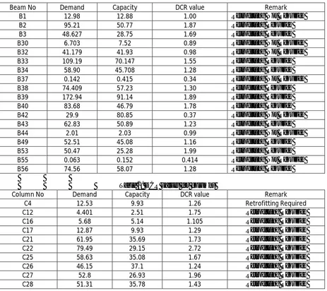
Table 1: DCR values for beams
Beam No Demand Capacity DCR value Remark
B1 12.98 12.88 1.00 Retrofitting Not Required
B2 95.21 50.77 1.87 Retrofitting Required
B3 48.627 28.75 1.69 Retrofitting Required
B30 6.703 7.52 0.89 Retrofitting Not Required
B32 41.179 41.93 0.98 Retrofitting Not Required
B33 109.19 70.147 1.55 Retrofitting Required
B34 58.90 45.708 1.28 Retrofitting Required
B37 0.142 0.415 0.34 Retrofitting Not Required
B38 74.409 57.23 1.30 Retrofitting Required
B39 172.94 91.14 1.89 Retrofitting Required
B40 83.68 46.79 1.78 Retrofitting Required
B42 29.9 80.85 0.37 Retrofitting Not Required
B43 62.83 50.89 1.23 Retrofitting Required
B44 2.01 2.03 0.99 Retrofitting Not Required
B49 52.51 45.08 1.16 Retrofitting Required
B53 50.47 25.28 1.99 Retrofitting Required
B55 0.063 0.152 0.414 Retrofitting Not Required
B56 74.56 58.07 1.28 Retrofitting Required
Table 2: DCR values for columns
Column No Demand Capacity DCR value Remark
C4 12.53 9.93 1.26 Retrofitting Required
C12 4.401 2.51 1.75 Retrofitting Required
C16 5.68 5.14 1.105 Retrofitting Required
C17 12.87 9.93 1.29 Retrofitting Required
C21 61.95 35.69 1.73 Retrofitting Required
C22 79.49 29.15 2.72 Retrofitting Required
C25 58.63 35.08 1.67 Retrofitting Required
C26 46.15 37.1 1.24 Retrofitting Required
C27 52.8 26.93 1.96 Retrofitting Required
III.RESULTSANDDISCUSSIONS
Reinforcement details of model 1 :for Beams,
Dimension of beams = 230mmX450mm Cover to steel0reinforcement (bottom) = 40mm
Main reinforcement : Top reinforcement = 2 no’s of 16mm dia Bottom reinforcement = 2 no’s of 16mm dia Shear reinforcement : at middle = 8mm dia @ 200mm c/c
At supports = 8mm dia @ 150mm c/c
Columns,
Dimension of beams = 230mmX450mm
Cover to steel0reinforcement (both side) = 40mm Main reinforcement = 6 no’s 16mm dia
Shear reinforcement = 8mm dia @ 200mm c/c
Slabs,
Main reinforcement = 10mm dia @ 150mm c/c Distribution reinforcement = 10mm dia @ 200mm c/c
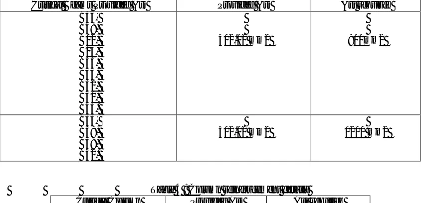
Table 3: Beam reinforcement details
Critical Beams Provided Ast Provided Ast Ast required B56,
B49, B02, B03, B53, B34, B32, B40, B43.
402.12 mm2 800mm2
B33, B38, B39, B42.
402.12 mm2 1200 mm2
Table 4 : Column reinforcement details
Critical Column Provided Ast Ast required Corner C17, C27,
C21, C16,
C04 1206.37 Mm2 2200 Mm2 Middle C25, C26,
C22, C28,
C12 1206.37mm2 4500 Mm2
Design of RCC Beam Jacketing as Per Is 15988:2013
Beams with reinforcement details for reinforcement of 800mm2
But ,when the0beams are designed to resist0lateral seismic forces, the reinforcement to be provided to0resist the seismicforces is, 4bars of 16mm Ø at both top and bottom gives 1608.48 mm2
Reinforcement deficiency = 1608.48 – 804.24 = 804.24mm2 Provide 4 bars of 16mm dia bars gives 804.24mm2
Minimum thickness for jacketing to be provided is 100mm. Therefore, revised beam will be 430x550mm. Provide shear reinforcement using 2 legged 8mm ф bars @ 150mm c/c.
Beams with reinforcement details for reinforcement of 1200mm2
The beams designed for0the structure are designed to0resist gravity loading and are provided with a0reinforcement of 2 bars with 16mm Ø at top and bottom gives 804.24mm2.
But ,when the0beams are designed to resist0lateral seismic forces, the reinforcement to be provided to0resist the seismicforces is, 4bars of 20mm Ø at both top and bottom gives 2513.27 mm2
Reinforcement deficiency = 2513.27 – 804.24 = 1709.03mm2 Provide 4 bars of 25mm dia bars gives 1963.5mm2
Minimum thickness for jacketing to be provided is 100mm. Therefore, revised beam will be 430x550mm. Provide shear reinforcement using 2 legged 8mm ф bars @ 125mm c/c.
Table 5: retrofit details for beams BEAMS SHEAR REINFORCEMENT
PROVIDED
ADDITIONAL REINFORCEMENT PROVIDED
TOP REINFORCEMENT BOTTOM
REINFORCEMENT B56 2L ∅8 @150 C/C #2 ∅ 16 #2 ∅ 16
B49 2L ∅8 @150 C/C #2 ∅ 16 #2 ∅ 16 B02 2L ∅8 @150 C/C #2 ∅ 16 #2 ∅ 16 B03 2L ∅8 @150 C/C #2 ∅ 16 #2 ∅ 16 B53 2L ∅8 @150 C/C #2 ∅ 16 #2 ∅ 16 B34 2L ∅8 @150 C/C #2 ∅ 16 #2 ∅ 16 B32 2L ∅8 @150 C/C #2 ∅ 16 #2 ∅ 16 B40 2L ∅8 @150 C/C #2 ∅ 16 #2 ∅ 16 B43 2L ∅8 @150 C/C #2 ∅ 16 #2 ∅ 16 B33 2L ∅8 @125 C/C #2 ∅ 25 #2 ∅ 25 B38 2L ∅8 @125 C/C #2 ∅ 25 #2 ∅ 25 B39 2L ∅8 @125 C/C #2 ∅ 25 #2 ∅ 25 B42 2L ∅8 @125 C/C #2 ∅ 25 #2 ∅ 25
Design of RCC Column Jacketing as Per Is 15988:2013
Column with reinforcement details for reinforcement of 2200mm2
The columns in0the building reinforcement0provided are with 6 bars of 16mm ø = 1206.37mm2.
Same0building is designed to0resist additional forces, reinforcement0to be provided is 8 bars of 20mm ø = 2513.27mm2
Reinforcement0deficiency = 2513.27 – 1203.37 = 1307 mm2
As0per IS 15988:2013 code, Area of steel for0jacketing = (4/3) As = (4/3) x 1307 = 1742.5mm2 Hence, 6 bars of 20mm dia gives 1885mm2. Hence, revised jacketed section is 330x650mm Lateral ties of 8mm at 200mm spacing are provided.
Column with reinforcement details for reinforcement of 4500mm2
The columns in0the building reinforcement0provided are with 6 bars of 16mm ø = 1206.37mm2.
Same0building is designed to0resist additional forces, reinforcement0to be provided is 12 bars of 25mm ø = 4908.7mm2
As0per IS 15988:2013 code, Area of steel for0jacketing = (4/3) As = (4/3) x 3705.36 = 4901.48mm2 Hence, 10 bars of 25mm dia gives 4908.7mm2. Hence, revised jacketed section is 330x650mm Lateral ties of 8mm at 200mm spacing are provided.
Table 6:retrofit details for columns COLUMN ADDITIONAL REINFORCEMENT
PROVIDED
SHEAR REINFORCEMENT PROVIDED
C04 #6 ∅ 25 2L ∅8 @ 200 C/C C16 #6 ∅ 25 2L ∅8 @ 200 C/C C17 #6 ∅ 25 2L ∅8 @ 200 C/C C21 #6 ∅ 25 2L ∅8 @ 200 C/C C27 #10 ∅ 25 2L ∅8 @ 200 C/C C12 #10 ∅ 25 2L ∅8 @ 200 C/C C22 #10 ∅ 25 2L ∅8 @ 200 C/C C25 #10 ∅ 25 2L ∅8 @ 200 C/C C26 #10 ∅ 25 2L ∅8 @ 200 C/C C28 #10 ∅ 25 2L ∅8 @ 200 C/C
IV.CONCLUSION
In this paper the study attempt0is made on weakening0points of structure, when the residential building is converted into commercial building. According0earthquake code0book IS 1893(PART-I) 2002, the analysis0is made on existing0building on ZONE II and soil0Type-II. Due to increase of load in the existing four storey structure, the beams and columns of the building got weaken. So, beams and columns retrofitting technique is adopted to regain its strength. Apart from increase in the0capacity and deformability, the0shear deformation0of the joint0panel will be reduced significantly0after retrofitting. Since slabs are parallel to earthquake forces, they need not to be strengthened. RC retrofitting technique enhances the axial load and moment carrying capacity in beams and column. Hence, it is concluded that retrofitting technique enhances the axial load and moment carrying capacity in beams and column.
REFERENCES
1. B ShivakumaraSwamy, Dhananjaiah M,” SEISMIC RETROFITTING OF R.C.FRAMES BY LINEAR STATIC METHOD AT SEVERE ZONE OF SOFT SOIL”.
2. PranayRanjan, PoonamDhiman,” Retrofitting of Columns of an Existing Building by RC, FRP and SFRC Jacketing Techniques”.
3. K Suruthi, P.Shakivel,”Seismic Qualification and Retrofitting Of Existing Structures”, Vol. 4, Issue 1, pp: (174-187), Month: April 2016 - September 2016.
4. Y. Krishna Chaitanya, Dr. S.R.K. Reddy, Dr. G. Raakesh Reddy,” Assessment, Analysis and Retrofit Methods of an Existing Building against Earthquake Forces”, Vol. 5, Issue 7, July 2016.
5. BHAVAR DADASAHEB O, DHAKE PRAVINCHANDRA D, OGALE RAMESH A,”Retrofitting of Existing RCC Buildings by Method of Jacketing”.
6. Shri. Pravin B. Waghmare,” MATERIALS AND JACKETING TECHNIQUE FOR RETROFITTING OF STRUCTURES”.
7. Gattu Ashok Kumar, B Harish Nayak,” Seismic Retrofit of RC Building Using Jacketing – A Review and Case Study”, Vol. 5, Issue 10, October 2016.
8. Sumit Bhardwaj, SabbirAhammedBelali,”A Review on Retrofitting”, volume 2 Issue 3 March 2015. 9. Ayush Srivastava,” Retrofitting - Comparative study of RC jacketing and FRP wrapping”.
10. Dr. G.S Suresh, Mr. Sachin V,” SEISMIC PERFORMANCE EVALUATION AND RETROFITTING OF RC MEMEBERS AND JOINTS. 11. ManotapaBhaumik, A V Asha,” Seismic Analysis and FRP Jacketing of 4-storey RC Building”.
12. IS 456 (2000), “Plain and Reinforced Concrete–Code of Practice”, Bureau of Indian Standards, New Delhi, India.
13. IS 15899:2013”Seismic Evaluation and Strengthening of Existing Reinforced Concrete Buildings” , Bureau of Indian Standards, New Delhi, India.