Division VII
HIGH FREQUENCY SEISMIC EVALUATION METHODS
FOR COMPONENT FUNCTIONALITY
John M. Richards1, Gregory S. Hardy2, and Kelvin L. Merz3
1 Technical Executive, Electric Power Research Institute (EPRI), USA 2 Senior Principal, Simpson Gumpertz & Heger Inc., USA
3 Senior Consultant, Simpson Gumpertz & Heger Inc., USA
ABSTRACT
Updated seismic hazards in the central and eastern United States (CEUS) often contain significant amounts of high-frequency vibratory motion. Previous studies concluded that high-frequency motions were, in general, non-damaging to components and structures that have strain- or stress-based potential failures modes. The studies also concluded that components, such as relays and other devices subject to electrical functionality failure modes, have unknown acceleration sensitivity for frequencies greater than 16 Hz.
The ability of some potentially sensitive power plant components to properly function during these high-frequency motions has been considered in prior studies but only in a limited manner. EPRI conducted shake table testing of a diverse set of common nuclear power plant safety system components considered to be potentially high-frequency sensitive. These components are typically relays and other control devices with intermittent states, which can be subject to change of state, contact chatter, signal change/drift, and other intermittent electrical functionality failure modes.
This paper will describe seismic evaluation criteria for demonstrating that components have adequate high frequency seismic capacity (greater than 15 Hz). In general, the evaluation criteria were derived from the procedures developed for conduct of Seismic Margin Assessments and Seismic PRAs. Included are (1) criteria for using the insights and data from the high-frequency test results to determine component seismic capacity, (2) estimated horizontal and vertical in-structure amplification factors for determining in-structure seismic demand in the 15 to 40 Hz range, and (3) horizontal and vertical high-frequency in-cabinet amplification factors for use in determining mounting point seismic demand.
INTRODUCTION
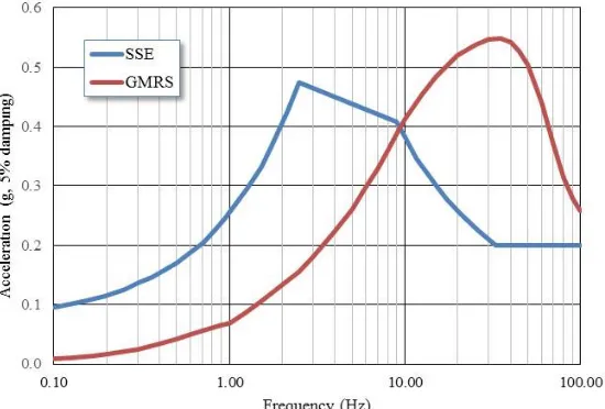
The risk posed by seismic events to nuclear power plants (NPPs) operating in the United States has been the subject of several studies conducted over the past three decades. The prerequisite for any plant seismic risk study is the determination of the seismic hazard associated with a given plant site. Recent seismic hazard studies for the operating plant sites have concluded that there is an increased high-frequency content in the seismic motions for the CEUS when compared to the original safe shutdown earthquake (SSE) response spectrum used for the design of many plants. Figure 1 shows an example ground motion response spectrum (GMRS) derived from a seismic hazard with significant high frequency content.
for Severe Accident Policy Resolution.” This appendix reviewed the bases for concluding that high-frequency motions were, in general, non-damaging to components and structures that have strain- or stress-based potential failures modes. It determined that components, such as relays and other devices subject to electrical functionality failure modes, have unknown acceleration sensitivity for frequencies greater than 16 Hz. Therefore, it was concluded that the evaluation of high-frequency vulnerability should be limited to components that are subject to intermittent states.
Figure 1. Example High Frequency Ground Motion Response Spectrum (GMRS)
In response to current Fukushima related seismic re-evaluation activities, EPRI published report 1025287 (EPRI, 2013) with guidance for evaluating NPPs using new seismic hazards and GMRS. That report includes the description of a program intended to more completely evaluate the potential impacts of high-frequency ground motions on component functional performance. The first part of the high frequency program involved shake table testing of approximately 150 components considered to be potentially high-frequency sensitive. Results of the testing are documented in EPRI 3002002997 (EPRI, 2014). The second part of the program, documented in EPRI 3002004396 (EPRI, 2016), developed guidance for evaluating installed plant equipment.
HIGH FREQUENCY EVALUATION CRITERIA
Guidance for applying the high-frequency test results for the re-evaluation of installed plant equipment is described in EPRI 3002004396 (EPRI, 2015). The overall evaluation process is outlined in Figure 2. For a selected set of equipment, the recommended evaluation process uses deterministic high confidence of a low probability of failure (HCLPF) capacity and conservative deterministic failure margin (CDFM) demand measures derived from the seismic margin assessment (SMA) relay evaluation procedure detailed in EPRI NP-6041 (EPRI, 1991b). The GMRS is recommended as the appropriate Review Level Ground Motion (RLGM) for purposes of this CDFM demand characterization.
Figure 2. High Frequency Evaluation Process
To determine which plant functions need to be reviewed, an optimized evaluation process is applied that focuses on achieving a safe and stable plant state following a seismic event. The objective of this approach is to provide reasonable assurance that key plant safety functions critical immediately following a trip/scram are preserved and thereby achieve this stable condition. Based on this concept, the critical functions to be included in the high frequency evaluation are:
Reactor Trip/Scram
RCS/Reactor Vessel Inventory Control
RCS/Reactor Vessel Pressure Control
Core Cooling
AC/DC Power Support Systems
Within the applicable functions above, the components that need high-frequency evaluations are contact control devices subject to intermittent states in seal-in or lockout circuits. Therefore, the objective of the review is to determine if seismic induced high-frequency component chatter would prevent the completion of the key functions.
ESTIMATING VERTICAL GROUND MOTION RESPONSE SPECTRA
Each operating nuclear plant in the United States has conducted a probabilistic seismic hazard analysis in accordance with the guidance contained in the EPRI 1025287 (EPRI, 2013) and has submitted the horizontal GMRS and supporting updated hazard results to the U.S. NRC. In order to perform a high-frequency component evaluation, a vertical GMRS is also necessary.
horizontal PGA levels between 0.20g and 0.45g and Vs301 values between 250 m/sec and 1,000 m/sec.
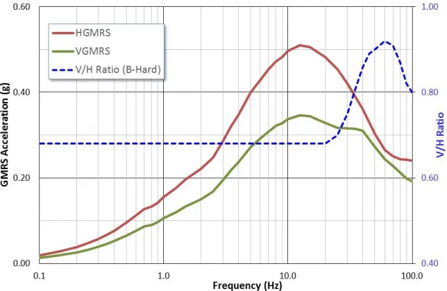
Three different methods were used to estimate frequency dependent ratios, with the final recommended V/H ratios taken as the mean of the three V/H ratios. Figure 3 shows a sample V/H ratio along with a typical horizontal GMRS and resulting vertical GMRS.
Figure 3. Typical V/H Ratio, Horizontal GMRS, and Vertical GMRS
ESTIMATING HIGH FREQUENCY IN-STRUCTURE AMPLIFICATION FACTORS
For plants that do not have in-structure response spectra (ISRS) consistent with the GMRS, guidance is provided for estimating the horizontal and vertical ISRS in the high frequency (≥ 15 Hz) range using the GMRS input motion. These high-frequency ISRS are estimated using structure amplification factors derived from reviews of an available set of recent response analyses of nuclear structures evaluated for high-frequency input motions. Sample seismic response analyses were reviewed for the following buildings.
A Westinghouse AP 1000 Nuclear Island Structure analysis
Two Auxiliary Buildings at a Pressurized Water Reactor (PWR) with recent ISRS calculations
An Auxiliary Building and a Control Building at a Boiling Water Reactor (BWR) with recent ISRS calculations
All of the analysis results were for sites with Vs30 values of 490 m/sec or greater, which was considered representative of sites with high-frequency ground motions. The structures considered in the analyses were reinforced concrete shear wall structures which are judged representative of the structures where the components are expected to exist (e.g., auxiliary buildings, control buildings and the overall nuclear island structures for the new plant designs). As such, these structure responses to high-frequency input represent a reasonable set of data from which to determine the HCLPF level amplification factors for use in the high-frequency evaluations.
High-frequency amplification factors were developed for each data point considered (nodes in the finite element model where seismic responses were reviewed) from the five structures subjected to the high frequency input motions. A high-frequency seismic amplification factor was developed for each of these data points based on:
The numerator defined as the peak (clipped) 5% damped response in the ≥ 15 Hz part of the ISRS
The denominator defined as the peak 5% damped response in the ≥ 15 Hz part of the GMRS used as input for each for the five structures reviewed in the seismic response analysis
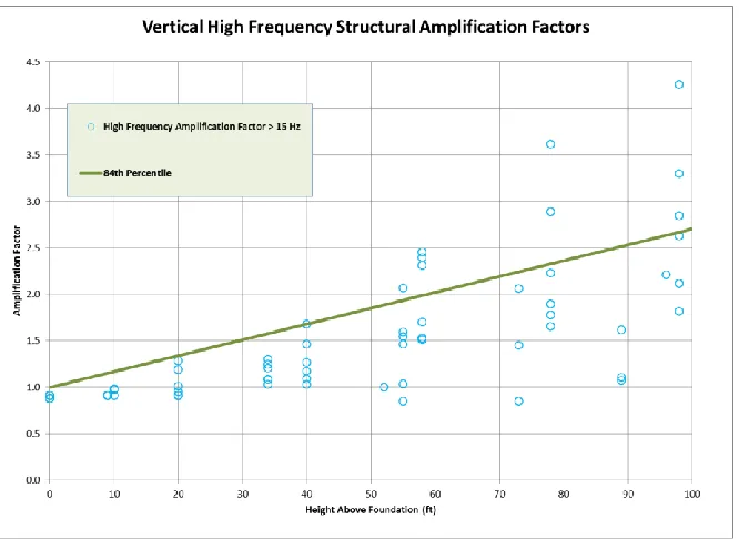
The resulting horizontal and vertical data were plotted as a function of the height above the foundation in order to assess the change with building elevation. A regression analysis of the data was then performed to calculate the 84% non-exceedance probability (NEP) in conformance with the criteria for generating a HCLFP response. Example vertical ISRS factors are shown in Figure 4.
Figure 4. High Frequency (≥15 Hz) Vertical 84% NEP Structural Response
ESTIMATING HIGH FREQUENCY IN-CABINET AMPLIFICATION FACTORS
For the high frequency evaluation process, the CDFM procedures developed in EPRI NP-6041 (EPRI, 1991b) are the recommended approaches. In general, a component mounted within a floor or wall anchored cabinet is subjected to the amplified cabinet filtered motion caused by the motion of the structure at the cabinet anchor points. The in-structure floor motion is, in turn, the structure-filtered motion caused by the broad-band ground motion. At elevations within the structure, the motion has the appearance of a sinusoid with random amplitude centered at a building frequency. The resulting response spectrum of this in-structure motion is a narrow-band frequency function. Appendix Q to EPRI NP-6041 (EPRI, 1991b) outlines the development of a procedure, denoted as "clipping," for converting narrow-band structure motion to an effective broad-band motion.
motion is determined by a CDFM cabinet amplification factor, AFc, which is associated with a given type
of cabinet construction. Effective cabinet amplification factors were developed assuming that the in-structure motion was broad-band; therefore, they are meant to be factored times the clipped narrow-band in-structure spectra to obtain an overall effective broad-band input level for the cabinet mounted component. These amplification factors are effectively clipped values of maximum cabinet transmissibility functions.
Horizontal In-Cabinet Amplification Factors
EPRI NP-7148 (EPRI, 1990) classified cabinet types as 1) high amplification structures such as switchgear panels and other similar large flexible panels, 2) medium amplification structures such as control panels and control room benchboard panels, and 3) low amplification structures such as motor control centers. The high- and the low-amplification enclosures have easily recognizable configurations while the medium amplification enclosures represent a broad range of control cabinet configurations. EPRI NP-7148, Appendix I (EPRI, 1990), identifies the recognizable characteristics of medium amplification cabinets and indicates certain configurations for which the amplification factors are not applicable.
Appendix Q to EPRI NP-6041 (EPRI, 1991b) recommended CDFM AFc values for the three
general cabinet types identified in EPRI NP-7148 (EPRI, 1990). These values are considered valid for both low- and high-frequency ranges since they are fundamentally associated with the application of clipping to effective cabinet transmissibility functions. The recommended horizontal CDFM AFc values are shown in
Table 1.
Table 1: Recommended Horizontal CDFM In-Cabinet Amplification Values
Cabinet Type
Recommended AFc
Motor Control Centers 3.6
Switchgear (flexible panels) 7.2
Control Cabinets (e.g., Control Room electrical panels and
benchboards) 4.5
Vertical In-Cabinet Amplification Factors
Vertical in-cabinet amplification factors were not previously considered in EPRI NP-6041 (EPRI, 1991b). Cabinets and structures were considered to have high vertical frequencies (> 20 Hz) which were not in the primary frequency range of ground input motions (2 to 10 Hz) considered for the original design evaluations. The new seismic hazard studies have resulted in vertical GMRS that are often equal or greater than the horizontal GMRS, with peak acceleration values occurring in the 25 to 35 Hz range for firm rock sites. These types of ground motions cause increased vertical response of both structures and cabinets mounted within the structures. Therefore, a generic vertical in-cabinet amplification factor is derived in Appendix C of EPRI 3002004396 (EPRI, 2015).
procedure developed in EPRI TR-103959 (EPRI, 1994). For the case of vertical amplification, test data was sparse since vertical cabinet response was considered to be negligible in older qualification testing programs. However, by considering an in-cabinet response spectrum as the result of a cascade of single degree of freedom (SDOF) responses, the resulting cabinet amplification may be estimated using random vibration theory. For an in-cabinet vertical oscillator located at a given cabinet position, the cabinet vertical response may be considered as an independent input to the in-cabinet oscillator, and thus the in-cabinet oscillator response can be considered as the response of two cascaded SDOF systems. The output of the first stage with frequency f1, or cabinet modal response of the primary vertical mode, is used as input to the
second stage, which is the response spectrum oscillator (on the cabinet) with frequency f2.
Figure 5 shows a normalized amplification function for the case of 7% cabinet damping and 5% in-cabinet response spectra damping. A cabinet damping of 7% is judged to be consistent with the median cabinet response estimate. Using the clipping method in EPRI TR-103959 (EPRI, 1994), the median peak value AF̆𝑇 = 6.5 and the resulting clipping factor is C̆𝑐= 0.46. The resulting median clipped level value is AF̆𝑐 = AF̆𝑇∗ C̆𝑐= 3.0 for determining the effective vertical demand for components mounted in all cabinet types. The randomness associated with the amplification factor is estimated as βr,AF = 0.11 and the clipping
uncertainty βu,cf = 0.28. Based on Appendix I to EPRI NP-6041 (EPRI, 1991b) the uncertainty in the peak
factor AF̆𝑇 is estimated as βu,pf ~ 0.23. The combined uncertainty for the amplification factor is then given
by βu,AF = [βu,cf2+ βu,pf2]½ = 0.36.
Figure 5. Fragility Vertical Cabinet Amplification Function with Clipped Level Indicated
Given the median value of AF̆𝑐 = 3.0, and the associated variability βr,AF = 0.11 and βu,AF = 0.36,
the range of HCLPF amplification factor values may be determined by using Equation I-4 in Appendix I to EPRI NP-6041 (EPRI, 1991b) for the four device capacity variability cases identified in Appendix I:
Case 1: βu,D = 0.18 βr,D = 0.09, resulting AFc, HCLPF = 4.72
Case 2: βu,D = 0.21 βr,D = 0.09, resulting AFc, HCLPF = 4.59
Case 3: βu,D = 0.27 βr,D = 0.135, resulting AFc, HCLPF = 4.30
Case 4: βu,D = 0.21 βr,D = 0.04, resulting AFc, HCLPF = 4.84
0 1 2 3 4 5 6 7
0 0.5 1 1.5 2 2.5 3 3.5 4 4.5 5
X
2/X
1
Frequency ratio, f2/f1
First Stage (cabinet) Damping = 7% Second Stage (oscillator) Damping = 5%
Since AFc, CDFM = AFc, HCLPF, the cabinet amplification factor to be used for estimating the vertical
demand for components mounted in all cabinets may be reasonably taken as AFc, CDFM = 4.7. This vertical
AFc for use in CDFM evaluations was derived in the same manner as was done for the horizontal
amplification factors for motor control centers and switchgear, and therefore reflects the same level of conservatism.
HIGH FREQUENCY COMPONENT EVALUATION
The high-frequency component evaluation process consists of comparing the CDFM mounting point demand with the deterministic HCLPF component capacity over the frequency range of interest. As described in EPRI 1025287 (EPRI, 2013), for the high-frequency evaluation, the frequency range of interest is 20 to 40 Hz.
The maximum horizontal mounting point demand accelerations are used as the component demand since the high frequency component capacities in EPRI 3002002997 (EPRI, 2014) were established using approximately equal test motion levels in all three directions. A geometric average of the three orthogonal test spectral acceleration levels was used to characterize the effective component test capacity. The effective wide-band component mounting point seismic demand is the maximum of the pair of the demand values computed as the product of the cabinet amplification factor and the clipped in-structure spectrum in each respective direction:
ICRScHor = AFcHor SAcHor , ICRScVer = AFcV SAcVer (1)
From EPRI NP-6041 (EPRI, 1991b), the effective wide-band component capacity is given by the effective spectral test capacity, SAT, divided by the CDFM knockdown factor, FK, and multiplied by
single-axis correction factor, FMS, if applicable. Values for FK and FMS are provided in Section 4 of
EPRI 3002004396 (EPRI, 2015).
TRS = (SAT/FK) FMS (2)
The seismic margin is provided by the capacity/demand ratio:
C/D = TRS/ICRSc (3)
As an example, consider a Square-D 8501 industrial control relay in a floor mounted Control Room benchboard installed in a control building 60 ft up from the building foundation, with a site horizontal GMRS as shown in Figure 6.
The Square-D 8501 industrial control relay was included in the EPRI High Frequency Test Program and achieved a high frequency test capacity of 11.9g (EPRI, 2013). Since the component test capacity is from the High Frequency Program and the component capacity is defined as a fragility threshold, EPRI 3002004396 (EPRI, 2015) defines the effective test capacity as SAT = 11.9g + 0.625g = 12.525g with
an Fk of 1.56.
The Control Room benchboard amplification factors AFc are 4.5 in the horizontal direction and 4.7
vertical. Control Room benchboards typically have horizontal natural frequencies in the lower frequency range so the horizontal and vertical responses are considered to be reasonably well separated and FMS is
taken as 1.2.
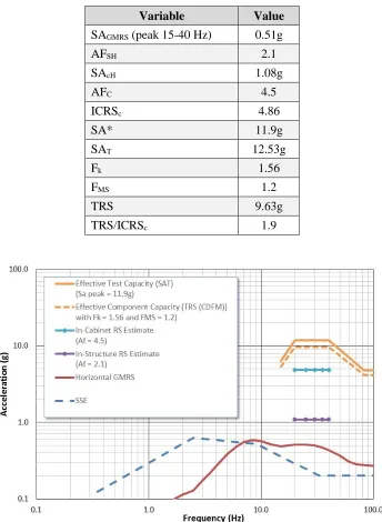
Table 2 shows a summary of the evaluation parameters for the horizontal direction. The peak horizontal GMRS acceleration between 15 and 40 Hz of 0.51g is scaled up by the applicable in-structure and in-cabinet amplification factors to achieve an effective mounting point demand level ICRSc of 4.86g.
The tested component capacity value of 11.9g is adjusted to 12.53g as described above, and scaled by the Fk and FMS factors to achieve the effective component capacity TRS of 9.63g. The same information is
Since the effective component capacity is greater than the mounting point demand, the component is seismically acceptable for the high frequency ground motions.
Table 2: Example Horizontal High Frequency Evaluation Parameters
Variable Value
SAGMRS (peak 15-40 Hz) 0.51g
AFSH 2.1
SAcH 1.08g
AFC 4.5
ICRSc 4.86
SA* 11.9g
SAT 12.53g
Fk 1.56
FMS 1.2
TRS 9.63g
TRS/ICRSc 1.9
Figure 6. Example Horizontal High Frequency Evaluation
HIGH FREQUENCY FRAGILITY GUIDANCE FOR SEISMIC PRAs
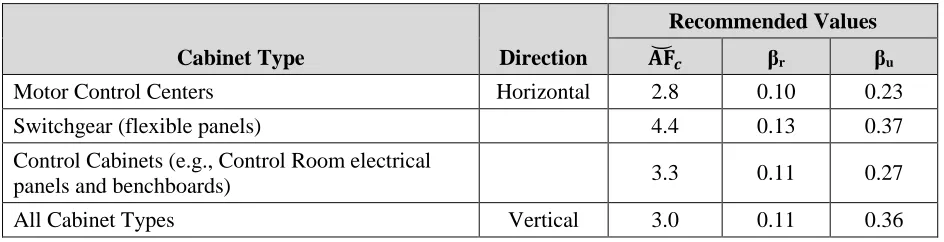
high-frequency case and a median vertical in-cabinet amplification factor is developed in EPRI 3002004396 (EPRI, 2015). The amplification factors and applicable β values are listed in Table 3. Additional fragility methodology guidance for the estimation of median component capacity, based on the high-frequency test program results, is also provided in EPRI 3002004396 (EPRI, 2015).
Table 3: Recommended Horizontal and Vertical Median Centered In-Cabinet Amplification Values
Cabinet Type Direction
Recommended Values
𝐀𝐅̆𝒄 βr βu
Motor Control Centers Horizontal 2.8 0.10 0.23
Switchgear (flexible panels) 4.4 0.13 0.37
Control Cabinets (e.g., Control Room electrical
panels and benchboards) 3.3 0.11 0.27
All Cabinet Types Vertical 3.0 0.11 0.36
CONCLUSIONS
Updated seismic hazards in the central and eastern United States (CEUS) often contain significant amounts of high-frequency vibratory motion. Previous studies concluded that high-frequency motions were, in general, non-damaging to components and structures that have strain- or stress-based potential failures modes. The studies also concluded that components, such as relays and other devices subject to electrical functionality failure modes, have unknown acceleration sensitivity for frequencies greater than 16 Hz.
EPRI 3002004396 (EPRI, 2015) provides guidance for applying the high-frequency test results for evaluations of installed plant equipment. The recommended evaluation process uses deterministic high confidence of a low probability of failure (HCLPF) capacity and conservative deterministic failure margin (CDFM) demand measures. The guidance uses in-structure and in-cabinet amplification factors to develop the broad-band horizontal and vertical effective component mounting demand for comparison to effective broad-band component capacities following the general guidance from EPRI NP-6041 (EPRI, 1991b).
EPRI 3002004396 (EPRI, 2015) also provides guidance for performing fragility calculations for Seismic PRAs in cases where the in-structure response spectra include significant high frequency motions.
REFERENCES
Electric Power Research Institute (1990). Procedure for Evaluating Nuclear Power Plant Relay Seismic Functionality. NP 7148, Palo Alto, CA, December.
Electric Power Research Institute (1991a). Industry Approach to Severe Accident Policy Implementation. NP-7498, Palo Alto, CA, February.
Electric Power Research Institute (1991b). A Methodology for Assessment of Nuclear Power Plant Seismic Margin (Revision 1). EPRI NP-6041-SL, Palo Alto, CA: August.
Electric Power Research Institute (1994). Methodology for Developing Seismic Fragilities, TR-103959, Palo Alto, CA, June.
Electric Power Research Institute (2013). Seismic Evaluation Guidance: Screening, Prioritization and Implementation Details (SPID) for the Resolution of Fukushima Near-Term Task Force Recommendation 2.1 – Seismic. EPRI 1025287, Palo Alto, CA, February.
Electric Power Research Institute (2014). High Frequency Program: High Frequency Testing Summary. EPRI 3002002997, Palo Alto, CA, September.