Implementation of Image Compression Using
CL-DCT on FPGA
M. Nisha Monnappa1, Sonia Kuwelkar2
Dept. of Electronics & Telecommunication, Goa College of Engineering, Goa, India1 Dept. of Electronics & Telecommunication, Goa College of Engineering, Goa, India2
ABSTRACT: Image compression scheme is based on CL-DCT transform (Cordic-Loeffler). The CL-DCT offers best tradeoffs between the computational complexity & the image quality compared to other algorithm of DCT. It operates in 1-D DCT domain eventually 2-D 8 point DCT can be obtained by calculating first the algorithm over the rows then over the resulting columns.The simulation results are verified for the CORDIC processor with the theoretical values. Further the Image compression will be implemented taking each block into consideration on FPGA.
KEYWORDS: CORDIC, cordic-loeffler, FPGA, WCSN, DCT, VLSI
I. INTRODUCTION
Image Compression technique or technology caters to two main purposes. These two purposes are during the process of storing or saving a file, an image or for that matter any video-in this the compression techniques helps the entity to occupy fever space then the actual size. The other purpose of image compression holds for is during transmission or communications of messages in the form of file, picture or video or audio. As far as the storage or memory design is concerned the technology has advanced. But when it comes to networking i.e. transmission capacity or bandwidth the story all together is different. Therefore here we can conclude that image compression plays a vital role in the image compression standard like JPEG.
Wireless communication is the need of the hour for every communication, it may be space, research and meteorology plays a crucial role. But one of the main disadvantages of wireless communication is it needs to deal with the issue of power. But the current research and development in wireless communication and microelectronics has helped to design battery powered system to help in processing and communicating. Implementing both on a single board, such a board is called a wireless sensor node which could be distributed in a region in order to collect the coveted data and send it to or communicate it to the sink node. These data packets are transmitted by a method of multi-hop mode. These methods constitute very less infrastructure which is designed by coordination between the sensor nodes [1]. The wireless sensor nodes gives rise to a more technical version called wireless sensor network collectively. When such network are embedded with the CMOS cameras in order to find an object, or its coordinates, or just to sense the presence of an obstacle [2, 3], such a network is called wireless camera sensor network(WCSN).
There are lot research and experiments conducted to design the image compression module of the WCSN keeping in mind the least resource and power available. There are two approaches that the work done can be categorized based on software and based on hardware. Software implementation has a serious issue of long processing time and leads to high energy consumption, so not in favour of WCSN therefore hardware is the best solution for image compression.
The primary objective of this thesis is
To design image compression circuit in verilog/VHDL.
II. RELATED WORK
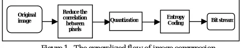
We need to understand the basic technique underlying technique of the image compression technology. The main goal of image compression is to reduce the level of entropy this can be done by reducing the redundancy level by encoding. By doing this we can reduce the number of bits the file occupies in the memory and so the bandwidth of communication also reduces. The figure below shows the image compression modules
Figure 1. The generalized flow of image compression
The original image is taken and it behaves as the input to the image compression circuitry. The image is encountered and goes in for processing is the image transform block. There are various transform which will be discussed later. The image to be compressed undergoes the reduction in the correlation between pixels in the image.
Quantization
After the image undergoes transformation for a better image compression ratio it has to be processed in the quantization block. The quantization block is said to be a lossy compression technique as the entropy is reduced. Some of the standards of image compression are JPEG and JPEG 2000 and they have their own methods to quantize and quantization table.
Entropy Coding
After quantization the compressed image is entropy coded so that the length of the image or file is further reduced. In this process the probability of the pattern that occurs more in the file is represented by less bits and vice versa. Therefore the probability of occurrence of the pattern is inversely proportional to the number of bits that are utilized to represent it.
When the image enters the DCT (Discrete Cosine Transform) or the transform block the DCT coefficient for each of the pixel value of the image is calculated. According to this process we are trying to convert the pixel value of the image to frequency domain that basically depicts the intensity of the image concentrated. This property of DCT is said to be energy compaction advantage of it. While calculating the DCT coefficient only few coefficients that are important are selected the others are eliminated further and could be quantized or entropy coded.
The Image compression schemes that are cited in papers and journals are as follows:-
• WHT-Walsh Hadarmard Transform
• DFT-Discrete Fourier Transform
• DWT-Discrete Wavelet Transform
• KLT- Karhunen-Loeve Transform
• DCT-Discrete Cosine Transform
One of the best approaches to code an image is DCT coding. JPEG also utilize the DCT and some of the various reasons as it’s very obvious are as follows.
• Low complexity
• Low memory
• Processing Time is less
• Best suited for hardware implementation
The DCT math was deduced by Ahmed, Natrajan and Rao in the year 1974[10]. This was a big leap in the research of image compression especially to solve the problem confronted by WCSN. The transform as mentioned earlier
Original image Reduce the correlation between pixels
Quantization Entropy
converted the pixel value to frequency domain. Now let’s try to put down the same equation of DCT in order to understand its capabilities and functionality.
The DCT equation given can be used to calculate the DCT of pixel value located at the ith row and jth column as follows in equation (1).
D(i,j) =
√ C(i)C(j) ∑ ∑ ( , )cos
( )
( ) 1
C (u) = √ = 0
1 > 0 2
When we take a look at the equation it hints us the complicated issue of high number of calculation for the matter of fact loads of multiplication in line. Multiplication in VLSI consumes lots of resources, the other way round the hardware and power needs to be big in that case. This implies and it appears to be not so good notion for WCSN. In short large silicon area creates problems.
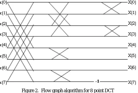
To solve this we need to look into the Flow Graph Algorithm (FGA) design of DCT. This helps to solve the problem of multiplication, at least to reduce the number of multiplication but does not eliminate it. Many researchers have been carried out on FGA as it is a kind of FDCT i.e. fast DCT which came to be very handy for VLSI implementation. The premier algorithm that was developed to solve the problem of reducing the number of multiplication was Loeffler algorithm [4] which proposed an FGA of 11 multiplication and 29 addition operations. Therefore this accounts to 40 % of the power and almost 45% of the total area [8].
The FGA for 8 point DCT is shown in figure 2 this flow graph algorithm is further optimized using different architectures.
Figure 2. Flow graph algorithm for 8 point DCT
The issue of the hour is to lessen the power to improve battery life in portable devices and to lessen the energy required during system operation.
Figure 3. 8-point DCT flow using CORDIC
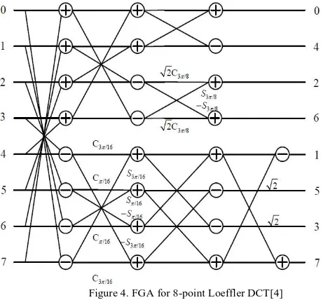
The Flow graph algorithm for Loeffler based algorithm is shown in figure 4. The C=cosx and S=sinx.
Figure 4. FGA for 8-point Loeffler DCT[4]
Figure 5. FGA of 8-point CORDIC based Loeffler DCT architecture [5].
The vector rotation for cordic algorithm can be realized. This realization can be done by rotating the vector (x,y) by
angle θ. The angle can be represented by the equation 3.
= . 2
With = 1,−1. 3
The equation vector above can be applied repeatedly using the equation in [6, 11], it’s given as below in equation 4
= − . . 2
= + . . 2
4
Trying to observe the equation 4 it implies that the equation requires only add and shift operation for implementing the hardware. After rotation the each step of iteration needs to be adjusted with a compensation factor‘s’. It can also be calculated by step by step iterative process.
= (1 + . ) = (1 + . )
With ∏(1 + . )≅
And = (0,1,−1), = 2 5
The design that is proposed is based on the proposed scheme is the usual module described earlier except that the module is optimized by choosing the best algorithm from the citations earlier. The important element that we need to keep in mind is while designing the image compression circuit is low complexity, low power, less hardware.
Table 1. DCT Algorithm comparison
The image compression circuit that has to be implemented is as shown in figure 6.
Figure 6. Image Compression circuit
Further the quantization block is calculated as per in the FGA and values are compensated at the end of the FGA as shown in figure 5. Hence we can see the compensated values act as the quantization table.
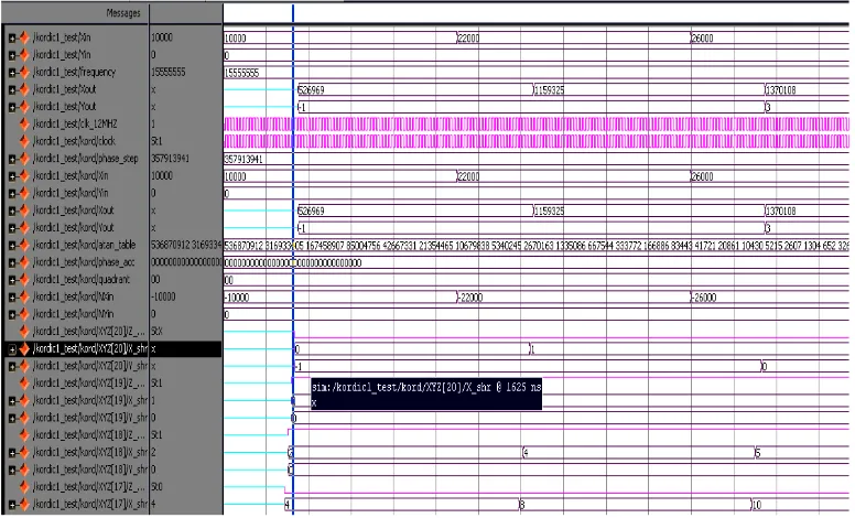
Table 2 Simulation Results for CORDIC design v/s calculated value
SR.NO Xin Calculated value
Simulation result
Error (%)
1 10000 527040 526969 0.01347
2 22000 1159488 1159325 0.01405
3 26000 1370304 1370108 0.01430
IV. CONCLUSION
The comprehensive study of the image compression and the best suitable circuit along with algorithm was done. Algorithm for CORDIC processor is designed successfully using verilog. The simulation result is compared with the calculated value and an average of 0.014% of error was observed. This result will be carried forward in order to build a best transform block for image compression and in turn implement the remaining blocks of Image compression circuit.
ACKNOWLEDGEMENT
I would like to thank my guide Mrs. Sonia kuwelkar for unprecedented encouragement and for the “never give up” attitude that she has inculcated in me.
REFERENCES
[1] F. Akyildiz, et al., A survey on sensor networks, IEEE Commun. Mag. 40 (Aug. 2002) 102–114.
[2] I.F. Akyildiz, T. Melodia, K.R. Chowdhury, A survey on wireless multimedia sensor networks, Computer Networks, vol. 51, no. 4, Elsevier, 2007, pp. 921–960, 14.
[3] Y. charfi, N. Wakamiya, M. Murata, Challenging issues in visual sensor networks, IEEE Wireless Communications 16 (2) (2009) 44–49. [4] C. Loeffler, A. Ligtenberg, G. Moschytz, Practical fast 1-D DCT algorithms with 11 multiplications, IEEE international Conference on acoustics, Speech, and Signal Processing (ICASSP 1989), Glasgow, UK, May 1989
[5] J. Liang, T.D. Tran, Fast multiplierless approximations of the DCT with the lifting scheme, IEEE Trans. on Signal Processing 49 (12) (2001) 3032–3044.
[6] H. Jeong, J. Kim, W.-K. Cho, Correlation low-power multiplierless DCT architecture using image, IEEE Trans. on Consumer Electronics 50 (1) (2004) 262–267.
[7] B. Heyne, C.C. Sun, J. Goetze, S.J. Ruan, A computationally efficient high-quality cordic based DCT, European Signal Processing Conference (EUSIPCO 2006), Proceedings, Florence, Italy, September 2006.
[8] Chi Chia Sung, Shanq Jang Ruan, Bo Yao Lin, and Mon Chau Shie, “Quality and Power Effcient Architecture for the Discrete Cosine Transform,”
IEICE Transactions on Fundamentals Special Section on VLSI Design and CAD Algorithms, Dec. 2005
[9] Low-Power Multiplierless DCT Architecture Using Image Data Correlation Hyeonuk Jeong, Jinsang Kim, and Won-kyung Cho, Member, IEEE [10] N. Ahmed, T. Natarajan, and K. R. Rao, "Discrete cosine transform," IEEE Trans. Comput., vol. C-23 pp. 90-93, 1974
[11] E.P. Mariatos, D.E. Metafas, J.A. Hallas, and C.E. Goutis, “A Fast DCT Processor, Based on Special Purpose CORDIC Rotators,” in IEEE
International Symposium on Circuits and Systems, May 1994, vol. 4, pp. 271–274.