1
Implementation of Continuous-Cast Concrete Base Slab for Future CANDU
®NPP
Homayoun H. Abrishami1, Medhat Elgohary1, Denis Mitchell2, John A. Bickley3, R. Doug Hooton4 and William D. Cook2
1
Atomic Energy of Canada Ltd (AECL)
2
Department of Civil Engineering and Applied Mechanics, McGill University, Montreal, Canada
3
John A. Bickley and Associates, Toronto, Canada
4
Department of Civil Engineering, University of Toronto, Canada
ABSTRACT
The reactor building concrete base slab for future CANDU® Nuclear Power Plants is to be built using one
continuous single pour, rather than segmental construction, in order to shorten the construction schedule and minimize the potential for cracking. Due to the relatively large size of the base slab, significant temperature gradients, resulting from the heat of hydration, can occur between the interior and the surfaces such that the resulting tensile stresses may cause cracking. The long-term performance of the base slab is strongly influenced by crack development, particularly at early ages. A research and development program has been carried out in order to implement this new approach, including studies on mix design, analysis techniques, and construction procedures to control the early-age risk of cracking. Successful implementation of the program recommendations will enable time-effective construction of a continuous-cast concrete base slab.
Laboratory and field-trial tests, together with thermal and stress analyses for the probable range of concrete mixes have been carried out in order to predict the mechanical properties, temperature variations, thermal stresses and risk of cracking for a large-pour concrete base slab. Mechanical and thermal properties, obtained from field trials were employed in the finite element thermal-stress analysis program in order to predict the time-dependent risk of cracking at early ages of the concrete base slab.
The development program provides the necessary recommendations and guidance on mix design, analysis tools and construction techniques to build the continuous-cast base slab for the reactor building.
INTRODUCTION
In the planning for the ACRTM (Advanced CANDU Reactor), particular attention is paid to design, structural
performance and constructability. The containment structure, being one of the major safety components of the plant, involves extensive design, analysis and documentation efforts. The containment structure is part of the containment system and constitutes the exterior structure of the ACR CANDU reactor building. It consists of a vertical cylindrical perimeter wall, founded on a continuous-cast concrete base, together with a hemispherical roof dome. The inside surfaces of the containment structure are lined with a carbon steel liner.
The perimeter wall and dome are prestressed with post-tensioning tendons in the horizontal and vertical directions as well as reinforcing bars in both directions. The base slab for ACR-1000 containment structure is a one-piece reinforced concrete flat plate having approximately 64.0 m diameter and 3.0 m thickness.
Experience with large volume pours is growing rapidly and with today’s availability of pumping technology, achieving large pours in a short time is possible. Continuous pours of 5000 to 6000 cubic meter can now be considered to be a viable option. The major benefit of large volume pours is the reduction in the total construction time. In addition, there are fewer construction joints, which are very expensive and labour intensive and become constrains to concrete shrinkage, thus resulting in cracking of concrete. The large amount of reinforcement crossing construction joints makes it difficult to form, strip and prepare the joints for the next concrete pour. There are examples of thick slabs that have been successfully carried out in Canada during the last 30 years. The CN Tower foundation, having 5.4 m thickness, was constructed in 1972-73 [1]. The Windsor Casino slab, with a thickness varying from 1.5 to 1.8 m and a continuous pour of 4,800 m3, was constructed in 1996 [2].
ACR BASE SLAB RESEARCH AND DEVELOPMENT PROGRAM
design, analysis techniques, and construction procedures to control the early-age risk of cracking. Successful implementation of the program recommendations will enable time-effective construction of a continuous-cast concrete base slab.
In practice, most of the standards and design codes recommend controlling the maximum temperature rise in mass concrete by appropriate construction techniques and material selection [3] and [4]. Many recent innovations in advanced concrete materials technology [5] and [6] have made it possible to produce modern concrete with exceptional performance characteristics. The use of high-performance concrete, with low-heat generation, is expected to aid in the control of thermal cracking, particularly at early ages.
EARLY AGE CHARACTERISTICS OF CONCRETE
Concrete Mixes-Laboratory Trials
The key in choosing a suitable concrete mix is to minimize the heat rise, the maximum temperature and the thermal gradient of the thick base slab. For the continuous casting process, the mix must be pumpable. Due to winter exposure conditions, during and after construction of the base slab, an air entrained mix is recommended. To achieve the 100 -year plant life a durable concrete is required.
Preliminary testing of the design mixes was carried out to finalize the probable range of concrete mixes for further testing. The preliminary design mixes involve a wide range of concrete mixes made with blended hydraulic cements similar to practical experiences of constructed projects.
Field Trials
The test results from field trial include compressive strength, elastic modulus, flexural strength, shrinkage, rapid chloride permeability and measured temperatures. Figure 1 shows the locations of the thermocouples in the one-meter cubes of concrete that were cast at the same time as the test samples. Figure 2 shows the temperatures measured near the centers of the 1 x 1 x 1m insulated cubes that were cast as part of the field trials. Mix 1, also termed Reference Concrete, represents a traditional structural mix without supplementary cementing materials. Mixes 2 (fly-ash concrete) and 3 (slag concrete), however, represent a family of mixes that can be formulated by replacing significant percentages of Portland cement with Suplementary Cementing Materials (SCMs). The mixes tested confirm the beneficial effects on temperature effects achieved by using SCMs. They are critical to achieving minimal heat rise (and fall) and limiting temperature gradients. By these measures even large mass concrete placements can be made without any significant cracking.
D1
D2, TC7
D3, TC2
TC8 TC3
TC1
TC5
TC4 TC6
250
250
1000 mm
Note: D3, TC7 and TC8 present for Mix 2 only 50 mm foam board
13 mm plywood
Figure 1. Thermocouple locations in one-meter field trial cubes of concrete
3
10 20 30 40 50 60 70
0.0 1.0 2.0 3.0 4.0 5.0 6.0 7.0 8.0
Time, days
T
em
p
er
at
u
re,
oC
Mix 2 - Fly-Ash Concrete Mix 1 - Reference Concrete
Mix 3 - Slag Concrete
Figure 2. Comparison of measured temperatures near center of insulated cubes for three different concrete mixes.
Transient Thermal Analysis
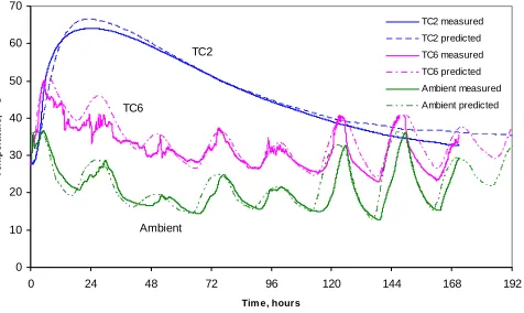
The computer program titled “Concrete Works – Version 1.0.5” [7] was used to determine the temperatures developed in the 1 m by 1 m cubes of concrete that were cast in the field trials and to predict the temperatures developed in the 64 m diameter base slab. In order to validate the thermal predictions and hydration models for the different mixes, two-dimensional” analysis was used. Thermal properties and ambient temperatures used in the program represented the actual field trial conditions. Figures 3, 4 and 5 compare the results of the analyses with the measured temperatures for the three different field trial cubes at near the center (TC2) and top surface (TC6).
0 10 20 30 40 50 60 70
0 24 48 72 96 120 144 168 192
Tim e, hours
T
e
m
p
er
at
u
re,
oC
TC2 measured TC2 predicted
TC6 measured TC6 predicted
Ambient measured Ambient predicted TC2
TC6
Ambient
Figure 3 Comparison of measured and predicted temperatures for Mix 1 (Reference Concrete) Field Trial.
0 10 20 30 40 50 60 70
0 24 48 72 96 120 144 168 192
Tim e, hours
T
e
mper
a
tur
e,
oC
TC2 measured TC2 predicted TC6 measured TC6 predicted
Ambient measured Ambient predicted TC2
TC6
Ambient
Figure 4 Comparison of measured and predicted temperatures for Mix 2 (Fly ash Concrete) Field Trial
0 10 20 30 40 50 60 70
0 24 48 72 96 120 144 168 192
Tim e, hours
T
e
mp
er
at
u
re,
oC
TC2 measured TC2 predicted TC6 measured
TC6 predicted Ambient measured
Ambient predicted TC2
TC6
Ambient
Figure 5 Comparison of measured and predicted temperatures for Mix 3 (Slag Concrete) Field Trial.
PARAMETRIC STUDY OF “RISK OF CRACKING” IN THE BASE SLAB
T
his study involves the analysis of the 64 m diameter base slab, using simple two-dimensional analyses, assuming that all of the concrete is placed at time zero. One of the main parameters was the type of concrete mix, with Mixes 1, 2 and 3 being studied. The second parameter is the total thickness of the base slab, assumed to be 2.5 m, 3.0 m and 3.5 m (identified as T1, T2 and T3, respectively). The third parameter investigated is the initial concrete temperature, assumed to be either 20oC or 30oC (identified as C1 and C2, respectively). The fourth parameter investigated is the ambient conditions at the timeof casting. Three ambient temperatures including May, July and October were investigated (identified as A1, A2 and A3, respectively). For the analyses, the site location was chosen to simulate a site in southern Ontario.
Concept of “Tensile Cracking Strain”
An interesting concept for evaluating the cracking resistance of concrete, particularly at early ages, is the use of the tensile strain capacity of the concrete [8], [9], [10[, and [11]. This concept was used in assessing the relative “risk” of cracking for the base slab as described below.
First, the thermal variation was determined from the thermal analysis using program “Concrete Works”. Using a FORTRAN program written to carry out this analysis from the predicted temperatures from Concrete Works, the thermal strain distribution at each time step was determined using a coefficient of thermal expansion of 10×10−6mm/mm /oC. The strain causing stress was then determined by adding a strain causing stress such that the total strain is linear over the height of the section (that is, plane sections remain plane) and the resultant axial load and moment are both zero. This analysis assumed that the modulus of elasticity was uniform over the thickness at one time step and that there was no external restraint on the base slab.
In order to assess the significance of the magnitude of the tensile strains predicted, the tensile cracking strain can be estimated as:
3
c c
c r
cr 0.133 10
4500 6 . 0
f 4500
f 6 . 0
E
f = = × −
′ ′ = =
ε (1)
where fr is the modulus of rupture and Ec is the modulus of elasticity. This value for the tensile cracking strain uses the CSA
code [12] expressions for fr and Ec. It is interesting to note that this approach assumes that the tensile cracking strain is
independent of f’c. It is noted that the use of this very simple indicator would be conservative for the following reasons:
a) Creep is ignored during early ages.
b) Due to the thermal variation over a section, the elastic modulus also varies and the modulus near the top (tensile) surface is typically less than the modulus near the centre of the base slab.
c) The true stresses are a result of incrementally applied thermal strains, while the analysis looks at the tensile strain at an instant with the concrete properties at that instant.
5
modulus, Ec,eff, where:
φ + = 1 E E c eff ,
c
(2)
For a value of the creep coefficient of 0.5, the limiting effective tensile cracking strain becomes:
(
c)
(
)
(
)
(
)
3c eff , c r eff ,
cr 0.200 10
4500 5 . 0 1 6 . 0 4500 1 6 . 0 1 f 4500 f 6 . 0 E
f = × + = × + = × −
+ ′ ′ = = φ φ
ε (3)
Tensile Cracking Strain Versus Time Prediction
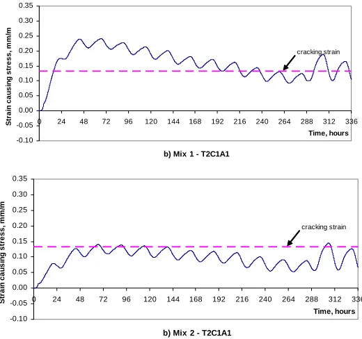
Figures 6 to 8 give the variations of the maximum tensile strain versus time during hydration for the typical cases made with and without fly ash. The tensile strains shown are determined for the top surface at the centre of the base slab using the procedure described earlier. Also shown in these plots is the “tensile cracking strain” of 0.133×10⁻³(0.133 mm/m), based on the CSA Standard [12] values for the modulus of rupture and the elastic modulus.
b) Mix 1 - T2C1A1
-0.10 -0.05 0.00 0.05 0.10 0.15 0.20 0.25 0.30 0.35
0 24 48 72 96 120 144 168 192 216 240 264 288 312 336
Time, hours S tr a in c a us in g s tr e s s , m m /m cracking strain
b) Mix 2 - T2C1A1
-0.10 -0.05 0.00 0.05 0.10 0.15 0.20 0.25 0.30 0.35
0 24 48 72 96 120 144 168 192 216 240 264 288 312 336
Time, hours S trai n c au si n g st res s, mm/ m cracking strain
Figure 6: Predicted top surface strains causing stress at centre of base slab for Mix 1 (Reference Concrete) and Mix 2 (Fly ash concrete) – Initial concrete temperature of 20oC (C1) cast May (A1) and 3 m (T2) slab thickness.
As can be seen from these figures the influence of the daily fluctuations of ambient temperatures is clearly evident in these plots. During the thermal analyses it was assumed that the curing blanket, consisting of wet burlap and a clear plastic sheet, was removed at 12 days (288 hours). It is noted in the presented curves that the blanket removal resulted in a spike in the tensile strains.
It is evident that Mix 2 (Fly ash Concrete) showed significantly lower tensile strains causing stress than Mix 1 (Reference Concrete). Also there is a higher risk of cracking for Mix 1 and lower risk of cracking for Mix 2. It is noted from these figures that increasing the slab thickness increases the tensile strain at the top surface. The combination of initial concrete temperature and ambient temperatures has a major influence, with cool concrete (C1) cast in hot weather (A2) resulting in the lowest predicted tensile strain causing stress.
a) Mix 1 - T1C1A3 -0.10 -0.05 0.00 0.05 0.10 0.15 0.20 0.25 0.30 0.35
0 24 48 72 96 120 144 168 192 216 240 264 288 312 336
Time, hours S tr a in c a us ing s tr e s s , m m /m cracking strain
a) Mix 2 - T1C1A3
-0.10 -0.05 0.00 0.05 0.10 0.15 0.20 0.25 0.30 0.35
0 24 48 72 96 120 144 168 192 216 240 264 288 312 336
Time, hours S tr ai n cau s in g st ress, m m /m cracking strain
Figure 7: Predicted top surface strains causing stress at centre of base slab for Mix 1 (Reference Concrete) and Mix 2 (Fly ash concrete) – Initial concrete temperature of 20oC (C1) cast October (A3) and 2.5 m (T1) slab thickness.
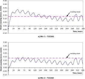
a) Mix 1 - T1C2A2 -0.10 -0.05 0.00 0.05 0.10 0.15 0.20 0.25 0.30 0.35
0 24 48 72 96 120 144 168 192 216 240 264 288 312 336
Time, hours S tr a in c a us in g s tr e s s , m m /m cracking strain
a) Mix 2 - T1C2A2 -0.10 -0.05 0.00 0.05 0.10 0.15 0.20 0.25 0.30 0.35
0 24 48 72 96 120 144 168 192 216 240 264 288 312 336
Time, hours S tr a in c a us ing s tr e s s , m m /m cracking strain
Figure 8: Predicted top surface strains causing stress at centre of base slab for Mix 1 (Reference Concrete) and Mix 2 (Fly ash concrete) – Initial concrete temperature of 30oC (C2) cast July (A2) and 2.5 m (T1) slab thickness.
7
CONSTRUCTION PROCEDUREExecution Plan
The base slab execution plan will consider both prescriptive and performance-based specifications. The performance criteria for durability to achieve a 100-year service life of the ACR containment structure will be specified. Material selection and concrete properties shall meet desirable thermal characteristics and still meet the strength specified. The two SCMs that would be considered for the base slab mix are granular slag and fly ash. As stated earlier, the use of either fly ash or slag reduces the temperatures and temperature gradients.
Because of the very large size of the base slab, prequalification trials including laboratory trials and field trials will
be carried out in order to meet desirable requirements such as workability for placing and pumpability to avoid any
unpredictable problem during the construction. Based on the measured material properties in the laboratory trials and the field trials, the relationships between the compressive strength, flexural strength and modulus of elasticity versus time will be determined. The data from the field trials will also enable these properties to be related to the temperature-time history (maturity concept).
Construction Issues
For a project of this magnitude involving the first construction of an ACR reactor, only prequalified contractors with successful previous experience with large-scale heavy industrial construction and large-pour concrete projects will be allowed to bid. The selected concrete supplier shall ensure continuous production with a backup plant available at all times in case of a breakdown or maintenance. Ahigh efficiency pre-mix plant arrangement with the required production capacity shall be used. Criteria for Quality Control (QC)/ Quality assurance (QA) requirements shall be specified in the quality control plan for site testing facilities, concrete production, qualification of site engineers, operators and other required personnel.
Concrete Placing
The most efficient way of placing this volume of concrete and delivering it to the changing locations required to keep all vertical and horizontal surfaces from setting prematurely is by the use of pumps and truck mounted booms. These can be obtained with a 33-m reach and with a boom that can cover a large area of the base overlapping each other. Three such pumps, stationed at 120o intervals around the perimeter of the base slab would be required to cover the base slab area.
Instrumentation
Thermocouples will be installed in the base slab to determine temperatures and temperature gradients. At each location a thermocouple will be placed 50 mm below the top surface, halfway between the top and bottom and 50 mm above the bottom surface. Sets of these thermocouples will be installed in the centre of the slab and at four locations around the perimeter at 90o intervals. Data loggers will take readings at 10 minute intervals so that the progress of the thermal history can be followed.
Slab Inspection
Despite all the measures to avoid concrete cracking, the complexity of the material/construction process, thermal stresses and autogenous and other types of shrinkage, may result in some cracking. Therefore, after form removal, the slab shall be closely inspected for any cracks and defects. The location and size of any cracks and defects will be logged and the need for any remedial action will be determined by the Engineer.
Safety
The International Atomic Energy Agency Code and Safety Guides Q1 to Q14 [14] cover Quality Assurance for Safety in Nuclear Plants and Other Installations (or equivalent accepted by AECL). Safety Guide Q11 [14], Quality Assurance in Construction, provides recommendations on how to fulfil the requirements of the Code in relation to the construction of nuclear power plants.
CONCLUSIONS
This study has led to the following conclusions:
1. The mixes tested confirm the beneficial effects on temperature effects achieved by using SCMc. They are critical to achieving minimal heat rise (and fall) and limiting temperature gradients.
2. The Fly Ash Concrete is the most promising of the three different concretes studied for construction of the base slab. The Slag Concrete ranks second and the Reference Concrete is not suitable for this application.
3. A thinner base slab has lower risk of cracking than a thicker base slab. 4. Cooler initial concrete temperatures result in a lower risk of cracking.
5. The combination of cool concrete, cast in hot weather conditions, gives the smallest gradient and the lowest risk of cracking, provided that the curing regime is strictly enforced.
6. In terms of the reliability of the results it is noted that the simplified two-dimensional series of analysis provides a qualitative comparison of the effects of the parameters studied.
7. Field trial tests and analytical studies showed that it is possible to build the base slab with a minimum risk of cracking due to the heat of hydration.
REFERENCES
1. Bickley, J.A. (1975). “Concrete Technology Aspects of CN Tower”, ASCE Journal of the Construction Division, Vol 101, No CO1, pp. 201-212.
2. Bickley, J.A., Hughes Y. and Wannamaker, D. (1998). “Placing 4,800 m3 of Concrete: ‘All in a Day’s Work’”, Proc. CSCE Annual Conf., Halifax, Vol. 1, pp. 177-186.
3. ACI 349-01. (2001). “Code Requirements for Nuclear Safety Related Concrete Structures”, American Concrete Institute, Farmington Hills, MI.
4. CSA-A23.1-04 (2004). “Concrete Materials and Methods of Concrete Construction”, Canadian Standards Association, Mississauga, ON.
5. Malhotra, V.M., Editor. (2006). “Recent Advances in Concrete Technology”, Eighth CANMET/ACI International Conference, Montreal, CI SP-235, ACI, 362 pp.
6. Shah, SP, and Ahmad, SH, Editors. (1994). “High-Performance Concrete: Properties and Applications”, McGraw-Hill, Inc., 403 pp.
7. Folliard, K, Schindler, A., Juenger, M., Rung, M., Poole, J. and Riding, K, (2005), “Concrete Works, Version 1.0, Users Manual”, Concrete Durability Center, Texas Department of Transportation.
8. Houghton, D.L., (1976). “Determining Tensile Strain Capacity of Mass Concrete”, ACI Journal Proceedings, Vol.73, No.12, pp. 691-700.
9. Thomas, M.D.A., Mukherjee, P.K, Sato, J.A., and Everett, M.F., (1995). “Effect of Fly Ash Composition on Thermal Cracking in Concrete”, in Fly Ash, Silica Fume, Slag and Natural Pozzolans in Concrete, ACI SP-153, Vol.1, pp. 81-98.
10. Harrison, T.A., (1981) “Early-Age-Thermal Crack Control in Concrete”, CIRIA Report 91, Concrete Industry Research and Information Association, London.
11. Tatro, S.B., Bombich, A.A. and Hess, J.R., (2000). “Case Histories of Mass Concrete Thermal Studies”, U.S. Army Corps of Engineers Report ERDC/SL TR-00-8, 62 pp.
12. CSA A23.3-04 (2004). “Design of Concrete Structures”, Canadian Standards Association, Mississauga, ON. 13. Mitchell, D., Khan, A.A. and Cook, W.D., (1998), “Chapter 6 – Early Age Properties for Thermal and Stress
Analyses during Hydration”, in Materials Science of Concrete V, Jan Skalny and Sidney Mindess, Editors, The American Ceramic Society, Westerville OH, pp. 265-305.
14. International Atomic Energy Agency, (2001), “Quality Assurance for Safety in Nuclear Power Plants and other Nuclear Installations”, Code and Safety Guides Q1-Q14, Safety Series No. 50-C/SG-Q.