Case Study Based on the Power Quality Issues
of Aircraft Electrical Power System Using
Active Filters
S.Sathyamoorthi
1, S.Sriram
2Assistant Professor, Dept. of Electrical & Electronics Engineering, Sasurie College of Engineering, Tirupur,
Tamilnadu, India1&2
ABSTRACT: A system of the advanced aircraft electric power system is developed under variable-speed constant- frequency (VSCF) operation. The frequency of the generator‟s output voltage is varied from 300-Hz to 900-Hz for different loading case-studies. Non-linear DC loads in addition to the different passive and dynamic AC loads are included in the simulation of the VSCF aircraft electric power system. Power conversions are obtained using pulse converters. A 540 V, aircraft DC-bus power quality is examined experimentally and by computer simulation during a short-circuit fault across the phase terminals of a 70 kW. The power quality characteristics of the studied VSCF aircraft electric power system are presented and the effectiveness of the proposed filters is demonstrated through compliance with the newly published aircraft electrical standards MIL-STD-704F.
I. INTRODUCTION
Generally, Conventional civil aircraft architecture consists of a combination of systems dependent on mechanical, pneumatic, hydraulic and electrical sources. These systems have drawbacks such as low efficiency, difficulty in detecting leaks regarding pneumatic system, using many gearboxes for mechanical system, heavy inflexible piping and potential leakage of dangerous and corrosive fluids for hydraulic system. The electrical power is very flexible and doesn‟t require a heavy infrastructure. Its major drawbacks are lower power density than hydraulic power and may result in higher risk of fire in case of a short circuit [1].
The increasing use and criticality of electrical systems on-board aircraft is driving the development of new fault-tolerant generator technologies [1–4] and new power distribution systems such as higher-voltage DC networks [5– 9]. However, the behavior of these integrated systems under fault conditions is not well understood, especially the propagation of transients around the system, which, if uncontrolled, may lead to further equipment malfunction or failure. MIL-STD-704F [10] describes allowable DC-bus power quality limits in terms of voltage deviation and current ripple.
Regarding the generating system of the aircraft there are three systems; the constant speed drive (CSD) generating system comprises a 3-stage regulated synchronous generator. A transmissions device interposed between the engine and the generator incorporates a hydro-mechanical variable-ratio drive unit. This unit consists of variable and fixed displacement hydraulic units as well as a differential gear unit. The power used to drive the generator is controlled and transmitted through the combined effects of the three units. The output frequency is maintained constant in the CSD system by means of a governor and the hydraulic units being controlled [2].
The output power of the aircraft system is equivalent to Boeing 767 power of 90-kVA per channel (Boeing 767 contains two channels with equal loads plus an auxiliary unit). In this model, different load combinations are adopted including passive and dynamic AC loads as well as DC loads. The DC loads are constant power, constant current and constant voltage loads. Two high-pass filters (HPF), first- and second-order filters, are designed and installed at the generator terminals to reduce harmonics generated from the used power conversion units.
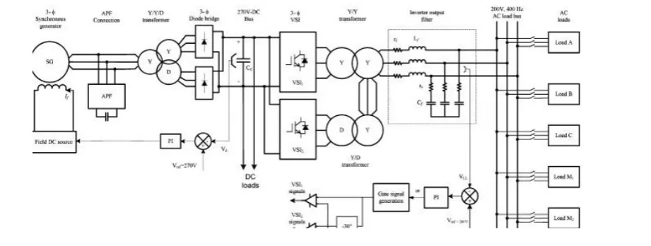
Fig :1 aircraft electric power system
II. CONSTRUCTION OF AIRCRAFT POWER SYSTEM
The EPS of the advanced aircraft includes the following elements [9]: internal combustion engine, electric starter/generators, integrated power units, solid-state power controllers, electric-driven flight actuators, electric-actuated brakes, electric anti-icing system, fault-tolerant solid state electrical distribution system, electric aircraft utility functions, electric-driven environmental and engine control. A simplified block diagram of the EPS of the advanced aircraft channel [9]-[11], is shown in Fig. 1. During starting mode, the battery (or the ground power) system provides power, through the interface power converter, to the electric machine which acts as a starter to the aircraft engine.
The TRU provides inherent high power factor and low total harmonic distortion (THD) of 13% [2]. According to IEEE standard [17], the THD value should be less than 5%. No switching is required for the rectifier and hence the losses are reduced and moreover, the diodes are normally very robust. A three-phase Y/Y/D transformer provides the necessary phase shift for the 12-pulse operation.
The output voltage of the TRU is regulated by controlling the field current of the synchronous generator using a feedback proportional-integral (PI) controller to meet the aircraft standard [20] and provide power to the 270V-DC bus. Three types of DC loads are connected to the regulated 270-VDC bus through different DC/DC converters as shown in Fig. 2. These loads are classified as; constant power (CP) load of 10-kW, constant current (CC) load of 100-A, 20-kW and constant voltage (CV) load of 28-VDC, 5.6-kW. The DC loads are regulated using PI controllers. To provide the constant frequency of 400-Hz at 200-VAC bus a 12-pulse sinusoidal PWM inverter is used. The 12-pulse inverter is controlled using a PI controller to provide the required voltage magnitude and frequency at the AC load bus.
III. CONTROL OF ENERGY STORAGE DEVICE
A multi-functional controller for the ESD is described which regulates the super capacitor current to meet transient load changes on the DC-bus, manages the super capacitor state of charge and mitigates DC-bus voltage transients such as those caused by generator short-circuit faults.
Super capacitor-based energy storage is proposed for a variety of applications in published literature, often as a power buffer between the load and the main power source [9, 20–29]. The control schemes are often based on a power balance between the individual hardware elements that form the system [20–22, 25–28]. These control schemes are inappropriate for this application, for example they are based on the vehicle speed [22],committed power generation [20, 26], generator speed-droop characteristic [27],estimated diesel engine output [25],or are designed to enable the main power source to have a constant output [21] or require many system level measurements [28], which if extrapolated to an aircraft system would be unmanageable and may introduce communication difficulties.
3.1 Control structure
The ESD, Fig. 4, comprises a 55F supercapacitor bank with a maximum voltage of 145 V and approximately 0.4 MJ of usable energy capacity and a simple, unisolated, bi- directional DC/DC converter [16]. A closed-loop controller is used to regulate the supercapacitor current, Isc, and the reference value for the current controller is determined by the combination of three signals. The first, Isc-L, is determined by the instantaneous DC-bus power calculation (Vbus × Ibus – where Vbus and Ibus are the bus voltage and current), which is then divided by supercapacitor voltage, Vsc. This forces the ESD to respond to instantaneous load changes on the DC-bus. The supercapacitor state-of-charge is managed by the second signal, Isc-rc, which is determined by the error between the supercapacitor reference voltage,
V∗ sc, here 135 V, and the
actual voltage. The third component, Isc-F, is determined by the error between the DC-bus voltage and the nominal set- point. This enables the ESD to support the bus voltage during generator faults.
3.2 Current control
The current control loop was designed using the averaged- value differential equations for the DC/DC converter, which assume lossless operation and ideal switches
Isc = Vsc −Vbus(1−D) LESD (1) Vbus = Isc(1−D)−Ibus +Igen Cbus (2)
where, D is the duty-ratio of S2 is the duty ratio of S1, Igen is the total generator DC current, LESD is the DC/DC converter inductor and Cbus is the combined filter capacitance on the DC-bus. A non-linear compensator is used to simplify the design of the current control loop in Fig. 4. The duty-ratio signal D is calculated by the non-linear
compensator as shown in (4), where V∗ESD is the output signal from the PI controller, Fig. 4. By substituting (4) into
the converter differential equation, (2), the overall transfer function between the control signal V∗ESD and the
supercapacitor current, Isc, is seen to have a simple linear first-order form, (5).
D = 1−Vsc −V∗ESD Vbus (3)
Isc V∗ESD = 1 sLESD(4)
Assuming that the PI controller has the form PI(s) ¼ kc((1+Tcs)/Tcs), where kc and Tc are the proportional and integral terms, respectively, then a unity gain cross-over frequency of v c may be obtained for the control loop by choosing kc ¼ v cLESD and Tc =10√ / v c. The ESD was assumed to have a switching frequency of 30 kHz, the filter inductor was 100 mH and the current.
3.3 Fault mitigation controller
remaining active phases, „d‟ and „e‟, increase to 90 A to supply the load. The imposition of the fault results in a very severe DC-bus voltage transient. which appears to the ESD power balance controller as a sudden reduction in DC-bus power, therefore the ESD responds with a negative IESD, light grey trace in , drawing power from the DC- bus which further reduces the DC-bus voltage.
IV. SYSTEM SIMULATION WITHOUT HARMONIC FILTERS
Using a 12-pulse converter at the generator terminals and a 12-pulse inverter at the 200-VAC bus does not reduce the harmonic contents to the standard value of 5% [20], [26]. At the generator terminals the harmonic contents appear in both voltage and current waveforms. At the 200-VAC bus, the most harmonic contents appear in the voltage waveforms due to PWM technique and the load current is less free of harmonics due to the nature of the inductive loads.
The aircraft electric power system shown in Fig. 1 is simulated using PSIM8. The generator speed is controlled to provide a continuous frequency range from 360-800-Hz. The aircraft generating system is loaded with different loading scenarios as listed in Table I for different loading percentages of full load. The passive, dynamic and DC loads are switched according to each case-study. In each case-study, the THD of the generator‟s current, I G, and voltage, V G, (at the generator terminals) are calculated.
The power factor (PF) at the generator terminals of the aircraft EPS for case-study No. 1 to case-study No. 7 are determined by the operation frequency. The higher PF values are recorded for case-study No. 3 where only DC loads are applied to the system. The lowest PF values are for case-study No. 4 where AC passive and dynamic loads are applied and case-study No. 7 where all loads are applied.
V. POWER PASSIVE FILTER DESIGN
When static capacitors are connected to a system, there is a frequency at which the capacitors are in parallel resonance with the power system inductive reactance. If the parallel resonance is at or near one of the characteristic harmonic frequencies produced by the converter, the filter circuit can be excited and large oscillating currents can flow between the inductive reactance of the power system and the capacitive reactance of the capacitors. These currents add to the harmonic voltage drop, causing a much larger voltage distortion factor. It is this resonant condition that causes problems involving conductive and inductive interference. Hence, capacitors should be sized to avoid a resonance near a characteristic harmonic frequency. The parallel resonant frequency ( ƒp) can be calculated as [26]:
Where MVA sc is the short circuit level at the point of study, Mvar c is the capacitor rating at the system voltage, X c is the reactance of the capacitor filter, X s is the reactance of the power system up to the filter location, L s is the corresponding inductance and f1 is the fundamental operation frequency which changes over the range 400-800-Hz.
It is required to calculate the range of the filter capacitor which makes parallel resonance with the inductance of the synchronous generator. To avoid such resonance the value of the capacitance of the filter shouldn‟t be in the range from 90- to 360-µF. It is found that, filter capacitance C f less than 90-uF corresponds to inductive PF, which is considered here.
A. First-Order High Pass Filter (RC filter) The first-order HPF is the simplest high-pass harmonic filter. It consists of a capacitor with a series resistance per phase. The value of the capacitance is chosen to avoid the parallel resonance with the aircraft power system from one side and on the other hand to keep the THD at the generator terminals as small as possible. The series resistance is calculated from the filter corner frequency and chosen to keep the filter losses minimum the at fundamental frequency range (400-800-Hz). Three different corner frequencies are chosen and the THD for generator voltage and current as well as the filter losses at fundamental frequency are calculated and compared to choose the best design. The filter parameters are calculated based on [10], [27-29].
second-order HPF. The same procedure of the first-second-order filter is adopted here for determining the second-second-order filter parameters [10], [28], [30].
C. Inverter Output Filter The inverter output passive filter consists of a series inductor having an inductance of 40-µH with a series resistance of 0.04-Ω and a shunt capacitor having a capacitance of 0.2-mF with a series resistance of 0.02-Ω. This filter is efficient to mitigate the harmonics generated from the 12-pulse sinusoidal PWM inverter before reaching the AC loads to values less than the standard limits for all case studies of operation and for all the frequency range of operation.
VI. SYSTEM SIMULATION WITH HARMONIC FILTERS
To study the effectiveness of the first-order (RC) and second-order (RLC) passive filters, either of the two filters is connected at the generator terminals and each time the THD of the voltage and current for case-studies No. 4 and 7 are calculated at different operation frequencies and plotted. The THD of generator current for both cases is always less than 5%. At higher frequency values, the THD of the generator voltage is less than 5% for RC filter while the THD values are almost constant for RLC filter and greater than 5% for case- study No. 7.
The PF at the generator terminals being dependent on the operation frequency after installing either RC or RLC filters is shown in Fig. 9 for case-studies No. 4 and 7. With RC filter the PF is slightly higher than that of RLC filter. With RC filter, the capacitor works as a power factor correction in addition to the filtering action. In RLC filter the inductance equalizes some of the capacitive reactance.
VII.CONCLUSIONS
The VSCF aircraft electric power system is modeled and analyzed under variable-speed constant-frequency operation. The modeled aircraft system is studied at frequency range of 400-800-Hz for different loading scenarios including passive and dynamic AC loads in addition to nonlinear DC loads of constant power, constant current, and constant voltage. The power quality characteristics of the modeled system are generated and analyzed. First-order and second-order high-pass filters are designed to reduce the harmonics at the generator terminals to levels below the standard values. The significant reduction in voltage deviations during normal events on the DC-bus when the ESD is online enables the limits in MIL-STD-704F to be respected. More generally the work in this paper illustrates the importance of energy storage in on-board power networks for a range of functions including power quality management, system stability and the control of transients on the prime mover. Optimizing these multiple objectives and the capacity of the ESD are topics for further research.
REFERENCES
[1] Rosero, J.A.; Ortega, J.A.; Aldabas, E.; Romeral, L.; “Moving towards a more electric aircraft”, IEEE Aerosp. Electron. Syst. Magazine, Vol. 22, Issue 3, pp. 3 – 9, March 2007.
[2] E.H.J. Pallet,” Aircraft electrical systems”, Pearson Prentice Hall, England, 1987.
[3] Vadher, V.V.; Smith, I.R.; Williams, S.; “Mathematical modeling of a VSCF aircraft generating system”, IEEE Trans. Aerosp. Electron. Syst., Vol. 22, No. 5, pp. 573 – 582, Sept. 1986.
[4] Howard and J. Edson, “Variable speed, constant frequency (VSCF) electric power distribution systems for aircraft”, IEEE Trans. Aerosp. Electron. Syst., Vol. 2, No. 4, pp. 290-297, Jul. 1966.
[5] T.-L. Ho, R.A. Bayles and E.R. Sieger, “Aircraft VSCF generator expert system”, IEEE Aerosp. Electron. Syst. Magazine, Vol. 3, No. 4, pp. 6- 13, Apr. 1988.
[6] C. Phillipson, M. Kansara and P.G. Holmes, “Three-phase VSCF induction generator synchronized by a single-phase supply through a passive single-element phase converter”, IEE Proceedings on Science, Measurement and Technology, Vol. 146, No. 3, pp. 153-158, May 1999.
[7] Y.S. Shiao and C.E. Lin, “A prototype induction generator VSCF system for aircraft”, International IEEE/IAS Conference on Industrial Automation and Control: Emerging Technologies, pp. 148-155, May 1995.
[8] J. Sun, M. Chen and K.J. Karimi, “Aircraft power system harmonics involving single-phase PFC converters”, IEEE Trans. Aerosp. Electron. Syst., Vol. 44, No. 1, pp. 217-226, Jan. 2008.
[11] I. Moir and A. Seabridge," Aircraft systems: mechanical, electrical, and avionics; subsystem integration", American Institute of Aeronautics and Astronautics, Inc. Reston, Virginia, 2001. [20] "MIL-STD-704F” Aircraft electric power characteristics", Military Standard, 2004.
[12] T. M. Jahns and M. A. Maldonado, “A new resonant link aircraft power generating system”, IEEE Trans. Aerosp. Electron. Syst., Vol. 29, No. 1, January 1993.
[13] G. Ferland, A. Chikhani, J.C. Cartier, "Harmonic and transient analysis of an aircraft electrical distribution system", Canadian Conference on Electrical and Computer Engineering, 14-17 Sept. 1993 pp. 668 - 671 Vol. 2, 1993.
[14] G. Gong, U. Drofenik, and J.W. Kolar, “12-pulse rectifier for more electric aircraft applications”, IEEE International Conference on Industrial Technology, Vol. 2, pp. 1096-1101, Dec. 2003.
[15] Chandrasekaran, S.; Lindner, D.K.; Boroyevich, D., “Analysis of subsystem integration in aircraft power distribution systems”, Proceedings of IEEE International Symposium on Circuits and Systems (ISCAS '99), Vol. 5, pp. 82-85, 1999.
[16] "IEEE recommended practices and requirements for harmonic control in electrical power system", ANSI/IEEE Std. 519- 1992.
[17] Herbert L. Ginn, III and Leszek S. Czarnecki, "An optimization based method for selection of resonant harmonic filter branch parameters" IEEE Trans. Power Delivery, Vol. 21, No. 3, pp. 1445-1451, 2006.
[18] Hyunjae, Y., Seung-Ki, S., Yongho, P., Jongchan, J.: „System integration and power-flow management for a series hybrid electric vehicle using supercapacitors and batteries‟, IEEE Trans. Ind. Appl., 2008, 44, pp. 108–114 25
[19]Joon-Hwan, L., Seung-Hwan, L., Seung-Ki, S.: „Variable-speed engine generator with supercapacitor: isolated power generation system and fuel efficiency‟, IEEE Trans. Ind. Appl., 2009, 45, pp. 2130–2135 26.
[20] Liyan, Q., Wei, Q.: „Constant power control of DFIG wind turbines with supercapacitor energy storage‟, IEEE Trans. Ind. Appl., 2011, 47, pp. 359–367
[21]Sang-Min, K., Seung-Ki, S.: „Control of rubber tyred gantry crane with energy storage based on supercapacitor bank‟, IEEE Trans. Power Electron., 2006, 21, pp. 1420–1427 28
[22]Tae-Suk, K., Seon-Woo, L., Seung-Ki, S., et al.: „Power control algorithm for hybrid excavator with supercapacitor‟, IEEE Trans. Ind. Appl., 2010, 46, pp. 1447–1455 29