1
A Hardware Wrapper for the SHA-3 Hash
Algorithms
Brian Baldwin
∗, Andrew Byrne
†, Liang Lu
‡, Mark Hamilton
∗, Neil Hanley
∗, Maire O’Neill
‡and William P.
Marnane
∗∗
Claude Shannon Institute for Discrete Mathematics, Coding and Cryptography.
Department of Electrical & Electronic Engineering,
University College Cork, Cork, IRELAND
Email:
{
brianb, markh, neilh, liam
}
@eleceng.ucc.ie
†
School of Mathematical & Geospatial Sciences,
RMIT University, Melbourne, Australia
Email: [email protected]
‡
The Institute of Electronics, Communications and Information Technology,
Queens University Belfast, Belfast, UK
Email:
{
l.lu, m.oneill
}
@ecit.qub.ac.uk
Abstract—The second round of the NIST public competition is underway to find a new hash algorithm(s) for inclusion in the NIST Secure Hash Standard (SHA-3). Computational efficiency of the algorithms in hardware is to be addressed during the second round of the contest. For software implementations NIST specifies an application programming interface (API) along with reference implementation for each of the designs, thereby enabling quick and easy comparison and testing on software platforms, however no such specification was given for hardware analysis. In this paper we present a hardware wrapper interface which attempts to encompass all the competition entries (and indeed, hash algorithms in general) across any number of both FPGA and ASIC hardware platforms. This interface comprises communications and padding, and attempts to standardise the hashing algorithms to allow accurate and fair area, timing and power measurement between the different designs.
I. INTRODUCTION
With the rapid growth of the internet, the need for protecting files and other information stored on computers has become of vital importance. Part of the requirement for trusted com-puting are cryptographic algorithms, used as network security measures to protect data during transmission, of which hash functions form an integral part as they operate at the heart of contemporary cryptographic protocols.
A hash functionHmaps a messagexof variable length to a string of fixed length. The process of applying H to x is called ‘hashing’, and the output H(x)is called the ‘message hash’ or ‘message digest’. Cryptographic hash functions are hash functions that possess the following properties:
• Pre-image Resistance. This requirement means that for a given hash value y, it should be computationally in-feasible for an adversary to find an input x such that
H(x) =y. Pre-image resistance is also known as ‘one-wayness’ [1].
• Second Pre-image Resistance. This implies that for a given input x1, it should be computationally infeasible
to find another inputx2, such thatH(x1) =H(x2). This
property is also known as ‘weak collision resistance’.
• (Strong) Collision Resistance. It should be computation-ally infeasible for an adversary to find any two distinct inputsx1 andx2, such thatH(x1) =H(x2).
Currently, NIST is holding a competition to develop a new cryptographic hash algorithm(s) [2], similar to the contest held to choose the Advanced Encryption Standard (AES) algorithm [3]. The new hash function(s) will be called SHA-3 (or the Advanced Hash Standard (AHS)), and may ultimately supersede the functions in the SHA-2 family. The contest initially received 64 submissions from designers all around the world, and 51 of these designs progressed through to the first round of the contest. The second round candidates were announced in Q3 of 2009 and the competing designs were reduced to 14. These hash algorithms are available for public comment and scrutiny and NIST has stated that computational efficiency of the algorithms in hardware, over a wide range of platforms, will be addressed during the second round of the contest [4]. Over the coming years the number of candidate designs will be reduced, until eventually it is planned to announce the successful hash function(s) in 2012.
Some initial work has already been completed on document-ing the hardware speed and size for different types of hard-ware, both by the authors [5][6] and others [7][8]. A webpage called the ‘SHA-3 Zoo’ has been set up by the Institute for Applied Information Processing and Communications (IAIK) in Graz to track these hardware implementation results [9].
Difficulties arise in comparison analysis when one considers that there are fourteen different designs, some of which have varying architectures for the different {224, 256, 384, 512}
ack_in
Controller
Register Shift Output
Unit Padding
Input Shift Register
lb_h_in dp_h_in ack_h_in dp_h_out ack_h_out
sel_in m mes_in
3 d_in w
Hash Block d_out
d hash_out
w
2 sel_out ctr_en
ctr_cl dp_in
lb_in lb_out
dp_out ack_out
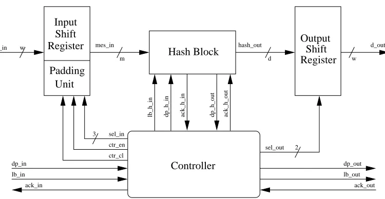
Fig. 1. Wrapper
measurements both between different vendors and in some cases between different families of the same vendor. This makes any form of comparison between implementations challenging.
A current topic of discussion within the cryptography com-munity is whether or not the padding for the hash function should be included in the hardware design, or implemented externally (for example in software) and therefore not taken into account when analysing the speed and area of any partic-ular SHA-3 candidate. The authors feel that while inclusion of the padding will increase the difficulty (and therefore the time taken to implement and test the designs), to not include padding can be viewed as incomplete results and as such give unfair advantage to certain hash functions over others, as some hash functions require a number of rounds of padding as standard, whereas others can process the padding with no extra rounds required. We also show in our results a case where the padding block contains the critical path of the design and as such affects the overall speed of the hash design.
As such, we attempt a compromise and present a wrapper that can be used to interface between any particular hash function algorithm and the outside world where the padding is included in the wrapper as opposed to the hash function block itself. In this way, ’fully autonomous’ designs can be easily and efficiently inserted inside the wrapper thereby allowing fast test times. It allows re-use of any padding scheme that can be used in multiple hash functions which cuts down on design time. It also alleviates any issues concerning designs which do not take into account bandwidth limitations or extra area or timing due to ’external’ stages.
While some very good attempts have been made to define a standard hardware interface for hash algorithms, such as those by Chen et al. [10], Gaj [11] and Kobayshi et al. [12], these concentrate on the communications aspect and assume in all cases that the padding is done either externally or within the hash function itself. Using our method, the area and timing measurement of any particular hash function implementation can be given inclusive of the hash function, communications and padding, or just the hash function as a stand-alone entity.
The rest of the paper is defined as follows; Section II presents our hardware interface and associated logic, in Sec-tion III we give an example of two of the current SHA-3 second round candidates, JH and Hamsi, using their 224-bit hash variants. These designs were chosen due to the large difference in the input message block size, 512-bits and 32-bits respectively. We give area and timing results computed for the hash functions both inclusive and exclusive of the wrapper for the two cases to show the different effect of the wrapper on hash functions which require large and small message sizes. We also give examples of how particular hash functions can be affected by communication bottlenecks. In Section IV we state our conclusions.
II. HARDWAREINTERFACE
The hardware wrapper can be best described in four main sections. In the first section, we give an overview of the hardware block as a whole. In the second section, we describe the interface signals connecting the wrapper to the hash block and also to the outside world. The third section describes the various padding schemes used and how they are generated. The fourth section lists and defines the constants that can be modified prior to synthesis.
A. Hardware Overview
Figure 1 shows a block diagram of the interface archi-tecture1. It comprises an input register which includes any padding required, an output shift-register and control circuitry. The input data can be set to any size, w, but for a represen-tation of a real world communications system, we set it to 32-bits, a standard word size. The input shift-register reads in and stores these w-bit values to the size required, m, which is the message block size of the hash function under test. If a message ends prior to this register being completely filled,
1Note that we have also developed variants on the design shown here which
padding is added to the partial message to bring it to the required size. The output shift-register performs a similar task, holding the hashed message digest of sized, while the output bus reads it outwbits at a time. The control circuitry controls the shift register operation, padding, and all communication signals.
B. Communications Protocol
Table I defines the various communication signals between the wrapper and the external world. It can be seen from Figure 1 that the communications protocol between the hash function and wrapper, as well as between the wrapper and the outside world is similar to that suggested by Gaj [11]. It differs however in the fact that a user wishing to hash a message does not need to do any preprocessing to their plaintext before sending the message, such as adding message length data, but only needs to set an end of message (EOM) signal high, in this case defined as a last block (lb in) signal either simultaneously with the last block of the message or at any time after transmission of the last message block.
While there is valid data on the line, a data present (dp in) flag is set high. To avoid the need to transmit a count of the number of valid message bits in the input block, and thus needing to know the lengths of message sections prior to transmission, the data present signal is set high when all of the data on the input bus are valid message bits, i.e. each message blocks read in is of sizew. When the wrapper reads in the data on (d in) it acknowledges that the data has been read in by setting (ack in) high. It is then ready to receive the next block of data. Conversely, when the message digest is ready to be read out on the output bus, (dp out) is set high by the function wrapper. This data will remain on the output bus until a return acknowledge (ack out) is received. The system then returns to its initial state in preparation for the next hash message.
TABLE I WRAPPERINTERFACE
Signal IO Description clk in Global clock
rst in Global reset, Active HIGH. Initialises the circuitry to begin hashing a new message d in in The input bus
dp in in Data present on the input bus
ack in out Data present on the input bus has been read lb in in Data present on the input bus is the
last block of the message to be hashed d out out The output bus
dp out out Data present on the output bus
ack out in Data present on the output bus has been read lb out out Data present on the output bus is the last
block of the hashed message
Table II defines the various communication signals between the hash function and the wrapper. These closely mirror the external signal lines, and in most cases perform equivalent functions between the hash block and the interface as the externals do between the interface and the outside world. However, there is no lb out equivalent as the hashed digest, d, is output to the output shift-register as one complete block.
TABLE II HASHINTERFACE
Signal IO Description clk in Global clock
rst in Global reset Active HIGH mes in in Data-in bus
dp h in in Valid data on Data-in bus
Set when buffer-in shift-register is full ack h in out Data present on Data-in bus has been read lb h in in Last block is present on Data-in bus
Inclusive of padding where required hash out out Data-out bus
ack h out in Data present on Data-out bus has been read. dp h out out Message digest is present on Data-out bus
C. Padding Protocol
There are many different padding schemes utilised by the designers of the hash functions, and in some cases varying padding schemes between the different sizes of the same hash function. Table III gives a brief outline of the various padding schemes used by the different round two candidates.
As can be seen from Table III, similarities between most of the different padding schemes allow us to generate a generic block for variants of Merkle-Damg˚ard strengthen-ing [1] paddstrengthen-ing schemes, as well as paddstrengthen-ings types of all-zeros or one-and-trailing-zeros.
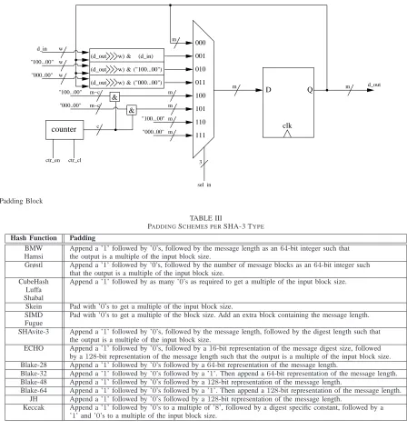
Figure 2 shows the block diagram of the selection process for some of the different padding schemes. The input wordw is saved in a register, and is shifted w-bits every subsequent input until the register is full. In this way, the message is read into the hash block when it is the required size m. If the message ends prior to filling of the register, the relevant padding scheme is selected via multiplexer. For example in the case of Fugue, the register is filled twice more, firstly with all zeros followed by an m-bit representation of number of message blocks. In the case of Shabal, append a one and zeros to the size of the register m. Using this method of filling up the register from the bottom-up allows for easy concatenation of the padding to the end of the input message block.
D. Design Dependent Options
Because of the different design methods and message sizes that comprise all the different hash functions, a number of user defined constants are specified at the top level of the VHDL and as such can be easily modified by the user to select the equivalent message size and padding scheme necessary to run a particular hash function. These constants are defined as:
• The hash function required.
• The counter size required for message length addition during padding.
• The message digest size required.
ctr_cl
D Q
clk &
&
w) (d_out
w) (d_out
w) (d_out
counter m
m
3 "100...00"
"000..00" d_in w
w w
m
m d_out
sel_in
111 110 101 100 011 010 001 000
m "000..00"
"100...00"
m m "000..00" "100...00" m−c
("100...00") ("000...00") & (d_in) & & m−c
c
ctr_en
Fig. 2. Padding Block
TABLE III
PADDINGSCHEMES PERSHA-3 TYPE
Hash Function Padding
BMW Append a ’1’ followed by ’0’s, followed by the message length as an64-bit integer such that Hamsi the output is a multiple of the input block size.
Grøstl Append a ’1’ followed by ’0’s, followed by the number of message blocks as an64-bit integer such that the output is a multiple of the input block size.
CubeHash Append a ’1’ followed by as many ’0’s as required to get a multiple of the input block size. Luffa
Shabal
Skein Pad with ’0’s to get a multiple of the input block size.
SIMD Pad with ’0’s to get a multiple of the block size. Add an extra block containing the message length. Fugue
SHAvite-3 Append a ’1’ followed by ’0’s, followed by the message length, followed by the digest length such that the output is a multiple of the input block size.
ECHO Append a ’1’ followed by ’0’s, followed by a16-bit representation of the message digest size, followed by a128-bit representation of the message length such that the output is a multiple of the input block size. Blake-28 Append a ’1’ followed by ’0’s followed by a64-bit representation of the message length.
Blake-32 Append a ’1’ followed by ’0’s followed by a ’1’. Then append a64-bit representation of the message length. Blake-48 Append a ’1’ followed by ’0’s followed by a128-bit representation of the message length.
Blake-64 Append a ’1’ followed by ’0’s followed by a ’1’. Then append a128-bit representation of the message length. JH Append a ’1’ followed by ’0’s followed by a128-bit representation of the message length.
Keccak Append a ’1’ followed by ’0’s to a multiple of ’8’, followed by a digest specific constant, followed by a ’1’ and ’0’s to a multiple of the input block size.
III. TESTRESULTS
Here we give example results of two of the SHA-3 round 2 candidates, namely JH and Hamsi, and show how the area and timing results vary dependent on whether the hash function is used inside the interface or as a stand alone entity. As mentioned previously, these particular hash functions were chosen because of their contrasting input message block sizes. We implemented the hash algorithms in VHDL and testing was done using Xilinx ISE 9.2 and the test platform was a Xilinx Virtex5 XC5VLX110. The results are taken from post-place-and-route map and timing reports.
A. JH Overview
Hongjun Wu designed the hash function family JH [13]. Its four variants {224,256,384 and 512} are based on the same compression function.
The compression function of JH combines a 1024-bit pre-vious hash block(Hi−1)with a 512-bit message block(Mi) to produce a 1024-bit hash bock (Hi). The output message digest is the truncation of the end of the last hash block to the required size.
The hash function consists of four main stages:
• Initialisation: The initial hash value, H0 is set according
to the message digest size.
• Message Padding: The message is padded with a ’1’, trailing zeros and a 128-bit vector equal to the message length so that it’s length is a multiple of 512-bits, with at least 512-bits of padding.
• Truncation: The message digest is determined by a trun-cation of the final hash value according the message digest size.
B. Hamsi Overview
The hash function Hamsi [14] was submitted by K¨uc¸¨uk from Katholieke Universiteit Leuven in Belgium.
Hamsi-224 and Hamsi-256 are both very similar using the same state size and number of rounds. Likewise with Hamsi-384 and Hamsi-512, which both use a larger state size and more rounds than Hamsi-224 and Hamsi-256. The Hamsi hash function is based on a
Concatenate-Permute-Truncate construction, influenced by both Grindahl [15] and
Serpent [16].
It consists of 4 main operations:
• Message Expansion: Implemented using linear codes.
• Concatenation: A 256-bit chaining value or an initial value to form the512bit state.
• Several rounds of a non-linear permutation
• Truncation: Selects the relevant bits for the output mes-sage digest once the non-linear permutation is complete.
C. Hardware Results
For the purposes of this examination, we concentrate ex-clusively on the smallest variant of each, the 224-bit hash. In this variant, JH has an input message size of 512-bits and Hamsi has an input message size of 32-bits. They both hash an output digest of size224-bits. We hashed a message of size 1024-bits to enable each hash function to perform a number of hashing rounds along with the finalisation round which includes the padding. While the area results are given both with and without the padding, the clock cycle count for the hash functions necessarily needs to include the time taken to hash the padding bits, as this is a fundamental part of hashing the message correctly. It is assumed that the hash as a stand alone unit has access to some form of external padding for the purposes of timing analysis, which is passed as part of the message block. We measure the area in slices and the time taken to hash the1024-bit block is calculated as follows:
Time= 1
Maximum Clock frequency×Number of Clock Cycles
For our implementation of JH using the ideal case512-bit input bus to maximise performance of the hash function, each message block requires38clock cycles, one for each of the36 input blocks and two more for the initial xor and for reading in the data. To hash the1024-bit message requires3hash rounds; two for the input message and one for the 512-bit padding block, thus giving 114 clock cycles. When the hash block is inserted in the wrapper, the same message requires138clock cycles. The latency is due to the initial reading in and out of the message inw-bit blocks. For subsequent message blocks, data is read in while the current data is being processed by the hash function, so the input latency only affects the first message block.
Hamsi, which operates on a message size of 32-bits, can process one message block in two clock cycles, one to read the
message and one to hash the round. For the1024-bit message, there are32blocks followed by three blocks of96-bit padding. The entire process exclusive of the wrapper takes 73 clock cycles and 83clock cycles when in the wrapper.
Table IV gives the breakdown for the cycle count for JH and Hamsi for a single message block. The table shows that both interfaces require 7 clock cycles to output the 224 -bit digest, on the 32--bit bus, w, and the other variants will naturally required/wclock cycles, wheredis the digest size, to transmit to the output. However, it can be seen that JH, with the larger message size, requires 16 clock cycles to load the initial data to the required message size. As such, any hash function requiring a large message size, m, will be subject to this latency of m/w clock cycles. This latency becomes especially apparent when hashing short messages where the data to be hashed is smaller than the message size required by the hash. Fugue and the other hash functions which operate over smaller message sizes wherem=wdo not suffer from this latency.
It is also interesting to note that while neither of these two hash functions are affected by a transmission bottleneck on the input, as in both cases the time taken to load a message is the same or less than that required to process a message, other hash functions are susceptible to this latency. An example of such a SHA-3 hash function that does is Keccak {224}[17]. Keccak requires 24 clock cycles per hash round, but is of block size 1152-bits, and therefore requires 36 clock cycles for message loading. This results in a delay of 12 clock cycles every message round while the hash block waits for the message block to read in data.
TABLE IV
SINGLE{224-HASH}MESSAGEBLOCKCLOCKCOUNT
Design JH Hamsi
Message size 512 32 Location Process Clks Clks
Wrapper Message Load 16 -Wrapper Data Transfer 1 1 Hash i/o Functions 2 7 Hash Message Block 37 3
Hash Last Block 37 2
Wrapper Hash output 7 7
TABLE V HASHRESULTS
Design Area Max. Freq. Clk Cycles Time
slices (M H z) (ns)
JH 1,394 303.0 114 376
Interface 1,558 188.8 138 731
Hamsi 1,704 70.5 73 1035
Interface 1,890 69.8 83 1189
embedded in the interface is caused by the critical path being through the128-bit counter required for the padding scheme, and as such, can be considered a part of the hash function even though the padding is processed through the interface. The time results for Hamsi show an increase for the interface. This is due to the data loading between the outside world, the interface and the wrapper. The increase in time for JH is obviously due to the decrease in clock frequency because of the critical path in addition to the data loading time.
IV. CONCLUSIONS
In this paper we have presented a hardware wrapper in-terface to enable fair and accurate comparison testing of the SHA-3 hash function competition entries, able to run across any number of hardware platforms. This interface comprises communication, padding, initialisation and finalisation, and attempts to standardise the timing and area measurement results between the different designs, in an attempt to aid the NIST competition body in their selection of an eventual winner of the SHA-3 competition.
V. ACKNOWLEDGEMENTS
This material is based upon works supported by the Science Foundation Ireland under Grant No. 06/MI/006.
The support of the Informatics Commercialisation initiative of Enterprise Ireland is gratefully acknowledged.
REFERENCES
[1] Alfred J. Menezes, Paul C. van Oorschot, and Scott A. Vanstone.
Handbook of Applied Cryptography. CRC Press, 1996.
[2] National Institute of Standards and Technology. Cryptographic hash algorithm competition. http://www.csrc.nist.gov/groups/ST/hash/sha-3/. [3] National Institute of Standards and Technology. FIPS PUB 197.
Advanced Encryption Standard, November 2001.
[4] National Institute of Standards and Technology. Announcing request for candidate algorithm nominations for a new cryptographic hash algorithm (SHA-3) family. Federal Register, 72(212):66212–66220, November
2007.
[5] Brian Baldwin, Andrew Byrne, Mark Hamilton, Neil Hanley, Robert P. McEvoy, Weibo Pan, and William P. Marnane. FPGA Implementations of SHA-3 Candidates: CubeHash, Grøstl, LANE, Shabal and Spectral Hash. In DSD, pages 783–790, 2009.
[6] Liang Lu, Maire O’Neill, and Earl Swartzlander. Hardware evaluation of SHA-3 hash function candidate ECHO. The Claude Shannon Institute Workshop on Coding & Cryptography, May 2009.
[7] Stefan Tillich, Martin Feldhofer, Mario Kirschbaum, Thomas Plos, J¨orn-Marc Schmidt, and Alexander Szekely. High-speed hardware implementations of BLAKE, Blue Midnight Wish, CubeHash, ECHO, Fugue, Grøstl, Hamsi, JH, Keccak, Luffa, Shabal, SHAvite-3, SIMD, and Skein. Cryptology ePrint Archive, Report 2009/510, 2009. http: //eprint.iacr.org/.
[8] A.H. Namin and M.A. Hasan. Hardware implementation of the compres-sion function for selected SHA-3 candidates. Technical Report 2009-28, CACR, 2009.
[9] IAIK. SHA-3 hardware implementations. http://ehash.iaik.tugraz.at/ wiki/SHA-3 Hardware Implementations.
[10] Zhimin Chen, Sergey Morozov, and Patrick Schaumont. A hardware interface for hashing algorithms. Cryptology ePrint Archive, Report 2008/529, 2008. http://eprint.iacr.org/2008/529.
[11] CERG at George Mason University. Hardware interface of a Secure Hash Algorithm (SHA). Functional Specification, October 2009. [12] Kazuyuki Kobayashi, Jun Ikegami, Shinichiro Matsuo, Kazuo Sakiyama,
and Kazuo Ohta. Evaluation of hardware performance for the SHA-3 candidates using SASEBO-GII. Cryptology ePrint Archive, Report 2010/010, 2010. http://eprint.iacr.org/.
[13] Hongjun Wu. The hash function JH. Submission to NIST, 2008.
[14] ¨Ozg¨ul K¨uc¸¨uk. The hash function Hamsi. Submission to NIST, 2009. [15] Lars R. Knudsen, Christian Rechberger, and Søren Steffen Thomsen.
The Grindahl hash functions, 2007.
[16] Eli Biham, Ross J. Anderson, and Lars R. Knudsen. Serpent: A new block cipher proposal, 1998.