Issue 1
PAGEPAC PLUS ZONE EXPANSION UNIT
V-5335100
by
PagePac
®INTRODUCTION
The Zone Expansion Unit (Z.E.U.) connects up to 16 zones of audio output (including talkback), contact closure outputs or inputs.
SPECIFICATIONS
(see Table 2)
FEATURES
• Provides same features as PP+ Controller • Maximum of 3 Z.E.U.s per Controller
Power Requirements
• Power from the PP+ Controller through the interconnect cable
Dimensions/Weight
• 16.00”W x 1.75”H x 6.875”D (40.64cm x 4.45cm x 17.46cm) • 3.0 lbs (1.35 kg)
Environment
• Temperature:0 to 40°C (32 to 104°F)
• Humidity: 5 to 95%
Locate in an area free of excess moisture, corro-sive gases, dust and chemicals.
INSTALLATION
MOUNTING
NOTE: When installing the Zone Expansion Unit, leave at least four inches of space above and below for proper ventilation.
Installing the paging equipment in a ventilated room where there is easy access to speaker cabling (preferably in the telephone equipment room). Disconnect all power before installing equipment.
1. Mount the Zone Expansion Unit(s)(Z.E.U.) to
2. Connect 8-pin Molex from Controller to first Z.E.U., and next Z.E.U’s, if used.
NOTE: Up to 3 Z.E.U.s can be used, providing up to 56 paging and/or control zones.
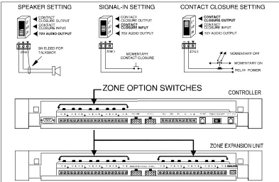
3. Set DIP switches on each Z.E.U.(s). 4. Set the Zone Option switches on the
Controller and Z.E.U.(s).
NOTE: For each zone used, no matter what its function, this switch needs to be set to one of three settings for proper zone operation before applying power to the system.
The Controller has eight switches for zones 1-8. Each subsequent Z.E.U. has switches for zones 9-24, 25-40, 41-56.
Refer to the Zone Map and Zone Configuration Tables filled out during facility paging system design. You can find these in the PagePac® Sys-tem Installation and Configuration Guide.
5. Locate and mount all speakers in accordance with the floor plan drawing for this installation. 6. Connect each speaker to the appropriate
Home Run or Speaker-to-Speaker wiring scheme as shown on the floor plan.
7. Test speaker wiring for short circuits.
Measure the resistance of each Home Run wiring with an ohmmeter. Any pair indicating a value of less than 15 Ohms must be rechecked for possi-ble shorted wiring or speakers. Correct any prob-lems and retest.
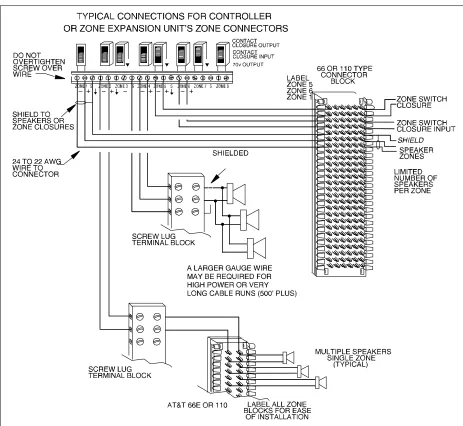
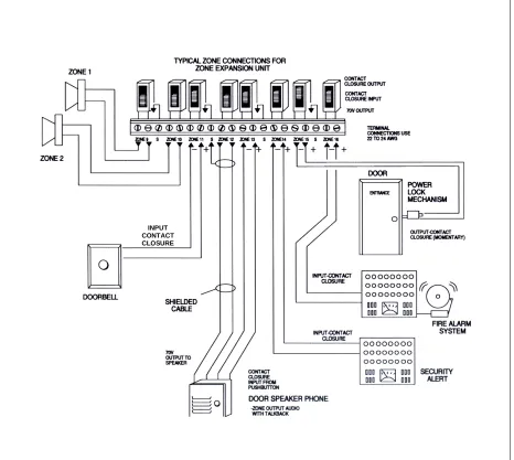
8. Make zone connections to Controller and Z.E.U. (see Figures 5 thru 7).
The zone connectors on the Controller and Z.E.U. can accommodate up to two 22 AWG wires or four 24 AWG wires per zone output. Check zone option switch setting with Zone Map and Zone Configuration tables as you connect each zone.
NOTE: DO NOT over tighten zone connector screws.
Powering Up System
With all zones wired and connected to the Con-troller and Z.E.U.(s), initial testing can begin. Once initial testing is done, you can begin to pro-gram the Controller with the features for each zone.
1. Plug the power cord into the AC input connec-tor on the AmpliCenter®. the following should happen:
a. The green Power LED on the AmpliCenter will turn on and stay on.
b. The green Page Access LED on the AmpliCenter also turns on, but will go out after a few seconds.
c. On the Controller, verify that the green Phone System Enabled LED is off. d. On the Controller, verify that the yellow
Attendant Access Enabled LED is off. e. The green Power LED on the Z.E.U.(s) will
turn on and stay on.
NOTE: If during power up, the system does not respond as described, refer to the Troubleshoot-ing section of this guide, and/or the PagePac® Plus System Installation and Configuration guide for detailed troubleshooting.
2. Begin programming the Controller.
A quick reference card for telephone program-ming, along with detailed programming instruc-tions, can be found in the PagePac Plus System Installation and Configuration Guide,
Programming.
TROUBLESHOOTING
Some common problems encountered when the paging system is not operating are described below. Check each item in the order listed.
1. No AC power to AmpliCenter or Controller (they supply power to the Z.E.U.(s)). 2. Host telephone system failure. 3. Host system page port failure.
4. A hardwire disconnect between host system and Controller.
5. AmpliCenter, Controller, or Z.E.U. zone switches or DIP switch settings tampered with.
If the problem has not been resolved by checking the preceding items, refer to the troubleshooting tables in the PagePac Plus Installation and Con-figuration Guide.
Controls and Indicators, Terminals and
Connectors
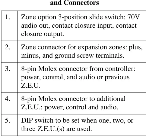
Figure 9 shows the controls and indicators, termi-nals and connectors on the rear panel of the Z.E.U.(s). Table 1 identifies them by function.
Table 1: Controls and Indicators, Terminals
and Connectors
1.
Zone option 3-position slide switch: 70V
audio out, contact closure input, contact
closure output.
2.
Zone connector for expansion zones: plus,
minus, and ground screw terminals.
3.
8-pin Molex connector from controller:
power, control, and audio or previous
Z.E.U.
4.
8-pin Molex connector to additional
Z.E.U.: power, control and audio.
5.
DIP switch to be set when one, two, or
TECHNICAL ASSISTANCE
When calling, have a VOM and a telephone test set available and call from the job site. Call (540) 427-3900 and ask for PagePac Technical Sup-port, or call (540) 427-6000 for Valcom 24-hour Automated Support or visit our websites at http://www.pagepac.com and www.valcom.com.
Should repairs be necessary, attach a tag to the unit clearly stating company name, address, phone number, contact person, and the nature of the problem. Send the unit to:
PagePac® Repair Dept. Valcom, Inc. 5614 Hollins Road Roanoke, VA 24019-5056
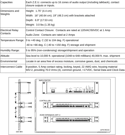
Capacities Each Z.E.U. connects up to 16 zones of audio output (including talkback), contact
closure outputs or inputs.
Dimensions and Weights
Height: 1.75” (4.4 cm)
Width: 16” (40.64 cm); 19” (48.3 cm) with brackets attached
Depth: 6.9” (17.53 cm)
Weight: 3.0 lbs (1.35 kg)
Electrical Relay Contacts
Control Contact Closure: Contacts are rated at 120VAC/50VDC at 1 Amp
Audio Zone: Contacts are rated at 2 Amps
Temperature Range: 0 to +40 deg. C (32 to 104 deg. F) operational
-40 to +66 deg. C (-40 to +150 deg. F) storage and shipment
Humidity Range: 5 to 95% (non-condensing) storage/shipment and operation
Altitude: Sea level to 10,000 ft. operational (1048 to 648 millibars) 40,000 ft. max. shipment
Environmental Locate in an area free of excess moisture, corrosive gases, dust, and chemicals
Interconnect Cable 8-position, 5 Amp contact rating, locking, keyed, 22 AWG wire, housing material
94V-2, providing 70.0 Vrms (4), common ground, +17VDC, Serial Data and Clock Data
Table 2. Z.E.U. Specifications
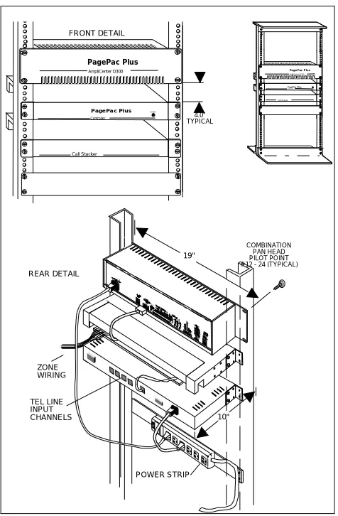
FRONT DETAIL
4.0" TYPICAL
POWER STRIP REAR DETAIL
ZONE WIRING
COMBINATION PAN HEAD PILOT POINT # 12 - 24 (TYPICAL)
19''
10'' TEL LINE
INPUT CHANNELS
POWER
PO WE R
PagePac Plus AmpliCenter D300
PagePac Plus
Controller
Call Stacker
PagePac Plus
Am pliC enter D 30 0
PagePac Plus
Con tro ller
Call Stac ker
Figure 2. Rack Mounted Hardware
Figure 5. Setting Zone Option Switches on Controller and Zone Expansion Units
INPUT CONTACT CLOSURE