NOVEL DIRECT TORQUE CONTROL BASED ON
SPACE VECTOR MODULATION WITH ADAPTIVE
STATOR FLUX OBSERVER FOR INDUCTION
MOTORS
Ibrahim Sk
1, Dr. Abdul Ahad
21
Student, Dept.Of EEE, Nimra Collage of Engineering & Technology, Ibrahimpatnam, VJA, (India)
2Prof &Head of Dept, Dept.Of EEE, Nimra Collage of Engineering & Technology, Ibrahimpatnam,
(India)
ABSTRACT
In this paper, we present a new approach to the Direct Torque Control (DTC) problem of three-phase induction
motor drives. By observing that the DTC objectives, which require the controlled variables to remain within
certain bounds, are related to feasibility rather than optimality, and by using a blocking control inputs regime
for the whole prediction horizon we derive a low complexity controller. So that in this paper we describes a
combination of direct torque control (DTC) and space vector modulation (SVM) for an adjustable speed
sensorless induction motor (IM) drive. The motor drive is supplied by a two-level SVPWM inverter. The inverter
reference voltage is obtained based on input-output feedback linearization control, and is compared with the
stator D–Q axes reference frame components and this are given to SVPWM inverter. Here we use
matlab/simulink for the simulation purpose. The proposed control algorithms are verified by extensive
simulation results.
I. INTRODUCTION
Enabled by significant technological developments in the area of power electronics, variable speed induction
motor drives have evolved to a state of the art technology within the last decades. The Adjustable Speed Drives
(ADS) are generally used in industry. In most drives AC motors are applied. The standard in those drives are
Induction Motors (IM) and recently also Permanent Magnet Synchronous Motors (PMSM) are offered. Variable
speed drives are widely used in application such as pumps, fans, elevators, electrical vehicles, heating,
ventilation and air-conditioning (HVAC), robotics, wind generation systems, ship propulsion, etc. These
systems, in which DC-AC inverters are used to drive induction motors as variable frequency three-phase voltage
or current sources, are used in a wide spectrum of industrial applications. One of the methods for controlling the
induction motor’s torque and speed is Direct Torque Control (DTC) [2], which was first introduced in 1985 by
Takahashi and Noguchi and is nowadays an industrial standard for induction motor drives. The basic
characteristic of DTC is that the positions of the inverter switches are directly determined rather than indirectly,
thus refraining from using a modulation technique like Pulse Width (PWM) or Space Vector (SVM) [1]
modulation. In the generic scheme, the control objective is to keep the motor’s torque and the amplitude of the stator flux within pre-specified bounds. The inverter is triggered by hysteresis controllers to switch whenever
switching table by reformulating the control problem as an PI controller for a two- and a three-level inverter. We
therefore propose an PI scheme based on feasibility with a prediction horizon N and an internal model of the
DTC drive for the predictions. We propose to switch only at the current time-step and to disregard switching
within the prediction horizon, which is equivalent to a move blocking strategy.
II. DESIGNING OF INDUCTION MOTOR
An induction motor (IM) is a type of asynchronous AC motor where power is supplied to the rotating device by
means of electromagnetic induction. Other commonly used name is squirrel cage motor due to the fact that the
rotor bars with short circuit rings resemble a squirrel cage (hamster wheel).An electric motor convert’s electrical
power to mechanical power in its rotor.
Fig: 1 The Equivalent Representation Of A Three Phase Two-Level Inverter Driving An Induction Motor
Fig: 2 The Voltage Vectors On The Dq Plane With Switch Positions
The ac induction motor is by far the most widely used motor in the industry. Traditionally, it has been used in
constant and variable-speed drive applications that do not cater for fast dynamic processes. Because of the
recent development of several new control technologies [5], such as vector and direct torque controls, this
situation is changing rapidly. The underlying reason for this is the fact that the cage induction motor is much
cheaper and more rugged than its competitor, the dc motor, in such applications. This section starts with
induction motor drives that are based on the steady-state equivalent circuit of the motor, followed by
vector-controlled drives that are based on its dynamic model as shown in the above figures 1 & 2.
III. MATHEMATICAL MODEL OF INDUCTION MOTOR
The three-phase motor is symmetrical,
Only the fundamental harmonic is considered, while the higher harmonics of the spatial field
distribution and of the magneto motive force (MMF) in the air gap are disregarded,
The spatially distributed stator and rotor windings are replaced by a specially formed, so-called
concentrated coil,
The effects of anisotropy, magnetic saturation, iron losses and eddy currents are neglected,
The coil resistances and reactance are taken to be constant,
In many cases, especially when considering steady state, the current and voltages are taken to be
sinusoidal.
Taking into consideration the above stated assumptions the following equations of the instantaneous stator phase
voltage values can be written:
Vqss = Rs iqss + dψqss/dt Vdss = Rs idss + dψdss/dt
The development of torque by the interaction of air gap flux and rotor mmf was discussed earlier in this chapter.
Hence it will be expressed in more general form, relating the d-q components [6] of variables. From equation
Te = (3/2)(p/2)ψ^mIrsinδ,
the torque can be generally expressed in the vector form as
Te = (3/2)(p/2) (ψdIq – ψqId)
IV. DIRECT TORQUE CONTROL (DTC)
Direct Torque Control (DTC) is a method that has emerged to become one possible alternative to the
well-known Vector Control of Induction Motors. This method provides a good performance with a simpler structure
and control diagram. In DTC it is possible to control directly the stator flux and the torque by selecting the
appropriate VSI state. A variety of techniques have been proposed to overcome some of the drawbacks present
in DTC [2, 8]. Some solutions proposed are: DTC with Space Vector Modulation (SVM); the use of a
duty--ratio controller to introduce a modulation between active vectors chosen from the look-up table and the zero
vectors; use of artificial intelligence techniques. A different approach to improve DTC features is to employ
different converter topologies from the standard two-level VSI. The major advantage of the three-level VSI
topology when applied to DTC is the increase in the number of voltage vectors available. This means the
number of possibilities in the vector selection process is greatly increased and may lead to a more accurate
control system, which may result in a reduction in the torque and flux ripples.
In principle the DTC method selects one of the six nonzero and two zero voltage vectors of the inverter on the
basis of the instantaneous errors in torque and stator flux magnitude.The block diagram of classical DTC
Fig:3 DTC control scheme
V. SPACE VECTOR PWM
The Space Vector PWM generation module accepts modulation index commands and generates the appropriate
gate drive waveforms for each PWM cycle. This section describes the operation and configuration of the
SVPWM module [7].
A three-phase 2-level inverter with dc link configuration can have eight possible switching states, which
generates output voltage of the inverter. Each inverter switching state generates a voltage Space Vector (V1 to
V6 active vectors, V7 and V8 zero voltage vectors) in the Space Vector plane (Figure: space vector diagram).
The magnitude of each active vector (V1to V6) is 2/3 Vdc (dc bus voltage).
The Space Vector PWM (SVPWM) module inputs modulation index commands (U_Alpha and U_Beta) which
are orthogonal signals (Alpha and Beta) as shown in Figure. The gain characteristic of the SVPWM module is
given in Figure . The vertical axis of Figure represents the normalized peak motor phase voltage (V/Vdc) and
the horizontal axis represents the normalized modulation index (M).
Fig:4 Space Vector Diagram
The inverter fundamental line-to-line Rms output voltage (Vline) can be approximated (linear range) by the
following equation:
VI. CONTROLLER DESIGN
6.1 Pi Controller
PI control [3] With a view to have a self-regulated speed, the speed of induction is sensed and controlled by
employing a suitable closed loop control. The speed of IM is sensed at a regular interval and is compared with
VII. SIMULATION
To verify the DTC-SVM scheme based on input-output linearization and adaptive observer, simulations are
performed in this section. The block diagram of the proposed system is shown in Fig 3.
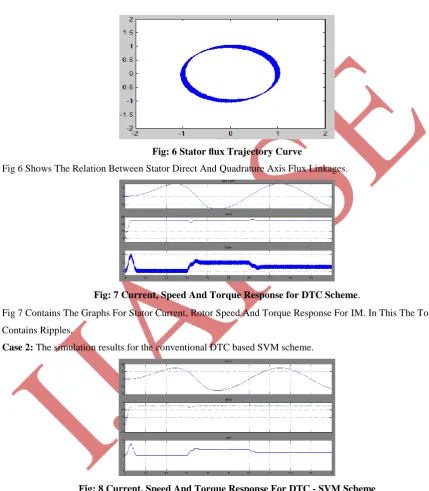
Case 1: The simulation results for the conventional DTC scheme.
Fig: 6 Stator flux Trajectory Curve
Fig 6 Shows The Relation Between Stator Direct And Quadrature Axis Flux Linkages.
Fig: 7 Current, Speed And Torque Response for DTC Scheme.
Fig 7 Contains The Graphs For Stator Current, Rotor Speed And Torque Response For IM. In This The Torque
Contains Ripples.
Case 2: The simulation results for the conventional DTC based SVM scheme.
Fig: 8 Current, Speed And Torque Response For DTC - SVM Scheme
Fig 8 contains the graphs for stator current, rotor speed and torque response for IM. In this the torque ripples can
be reduced by SVM modulation technique.
VIII. CONCLUSION
In this paper a novel DTC-SVM scheme has been developed for the IM drive system, which is on the basis of
stator voltage vector is obtained to fully compensate the stator flux and torque errors. The stator flux and speed
are estimated synchronously. By designing the constant observer gain matrix based on state feedback control
theory, the robustness and stability of the observer systems is ensured. Therefore by this proposed converter, the
drive system is steadily working, in very low speed, has much smaller torque ripple and exhibits good dynamic
and steady-state performance.
REFERENCES
[1] Zhifeng Zhang, Renyuan Tang, Baodong Bai, and Dexin Xie, “Novel Direct Torque Control Based on
Space Vector Modulation With Adaptive Stator Flux Observer for Induction Motors” IEEE
TRANSACTIONS ON MAGNETICS, VOL. 46, NO. 8, AUGUST 2010.
[2] Y. S. Lai and J. H. Chen, “A new approach to direct torque control of induction motor drives for constant
inverter switching frequency and torque ripple reduction,” IEEE Trans. Energy Convers., vol. 16, no. 3, pp.
220–227, 2001.
[3] S. Mir, M. E. Elbuluk, and D. S. Zinger, “PI and fuzzy estimators for tuning the stator resistance in direct
torque control of induction machines,” IEEE Trans. Power Electron., vol. 13, no. 2, pp. 279–287, 1998.
[4] F. Bacha, R. Dhifaoui, and H. Buyse, “Real-time implementation of direct torque control of an induction
machine by fuzzy logic controller,” in Proc. ICEMS, 2001, vol. 2, pp. 1244–1249.
[5] Takahashi and T. Noguchi, “A new quick-response and high efficiency control strategy of an induction
motor,” IEEE Trans. Ind. Appl.,vol. IA-22, no. 5, pp. 820–827, 1986.
[6] D. Seyoum, M. F. Rahman, and C. Grantham, “Simplified flux estimation for conrol application in
induction machines,” in IEMDC’03, 2003, vol. 2, pp. 691–695.
[7] G. Xi, H. Gao, and W. Xu et al., “A method to determine gain matrix of stator flux full order observer,” J.
Cent. South Univ. (Science and Technology), vol. 39, no. 4, pp. 793–798, 2008.
[8] J. Soltani1, G. R. A. Markadeh, and N. R. Abjadi3 et al., “A new adaptive direct torque control (DTC)
scheme based-on SVM for adjustable speed sensorless induction motor drive,” in ICEMS 2007, Seoul,
Korea, Oct. 8–11, 2007, pp. 497–502.
[9] I. Takahashi and T. Noguchi, “A new quick-response and high efficiency control strategy of an induction