c
Owned by the authors, published by EDP Sciences, 2012
Quasi-static and dynamic behaviour of the bone structures with fine
geometric and materials modelling aspects
O. Mayeur, G. Haugou, F. Cha ˆari, R. Delille, P. Drazetic, and E. Markiewicz
LAMIH UMR 8201 - CNRS, University of Valenciennes, 59313 Valenciennes Cedex 9, France
Abstract. The principle aim of this study is to highlight the influence of velocity on mechanical responses of cortical bones. Quasi-static tests are performed on cubic samples from bovine femurs in order to highlight the anisotropic effect of cortical structure. Thanks to the Hopkinson bars technique, a set of curves will be obtained and analysed to define precisely mechanical behaviour of porosity and loading directions. Therefore, this technique combined with a precise geometrical measurement based on µCT technique is expected to provide a more accurate representation of the mechanical behaviour of biological tissues. This protocol will be applied on human tissues after validation of geometrical and material correlation in order to increase the biofidelity of human body models.
1 Introduction
The decrease of injuries in road accidents is a challenging task and the improvement in this science requires more and more numerical tools for future evaluations of new generation of cars. To access the safety system, numerous models of the human body have already been populated. Labman (Lizee [1]), Thums (Iwamoto [2]), Humos (Behr [3]), were published as incomes of European consortiums or as car manufacturer initiatives. These models are con-strained by simplification needed for global testing and are limited in their biofidelity. In this context, the knowledge in biomechanics needs to be increased partly thanks to more accurate studies in mechanical behaviour of the skeleton. This research challenge is based on improvement of the mechanical behaviour of bone. Bone is a hard mineralized tissue consisting of a fibrous, organic matrix bound by inorganic salts (Viano [4]). As a matter of fact, the major difference between cortical bone and cancellous bone is due to the degree of porosity of the material. Cortical bone has porosity under 30%, while cancellous bone has a porosity ranging from 30 to 90% (Viano [4]). Different mechanical tests on cortical bone are performed during the past decades. This characterisation on biological material is a relevant task due to the anisotropies, heterogeneities and nonlinearities. The strain rates in tensile were studied on bovine bones on quasi-static by Katz [5], and dynamic at strain rate at 100 s−1(Wright [6], Crowninshield [7] and Ferreira [8]) and on SHTB from 300 s−1to 1000 s−1(Parish [9]). The present study tries to highlight the influence of velocity on cortical structure responses through quasi-static and dynamic tests. Thanks to compression testing machines and Hopkinson bars, a set of strain-stress curves is obtained and analysed to define precisely mechanical behaviour of cortical bone on fresh bovine femur. The main interest of this study is to combine the mechanical test to the generation of accurate geometrical measurement.
2 Material and method
2.1 Sample harvesting and preparation
This study is based on bovine femur as a feasibility step to human bones on future work. Cubic shape sample are
harvested from 2 bovine femurs (first one on quasi-static test and second one for dynamic tests). This procedure em-ployed surgical saw for debit step and a precision cut-off machine with diamond wheels (STRUERS, Secotom10) to finalise the sample shape. The first extraction with a surgical saw produces flat coupon of bovine femur. For the quasi-static compression tests, the samples dimensions are about 4 mm. This limited size is adapted to the me-chanical test machine. Due to this reduced size of sample, dimensions are not perfect but the measurement of the real section area can be ensured by the micro tomography acquisition of each sample (Fig. 2). The sample location is also determined in order to study its influence on the mechanical behaviour. Concerning the dynamic tests performed on SHPB, the equilibrium forces is controlled by element size. So these tests are carried with 7 mm cubic samples. This size ensured the best elastic waves’ equilibrium. A total of 59 samples has been tested under quasi-static (40) and dynamic (19) configuration (Fig. 1). Samples are tested in axial, radial and transverse direction and porosity is also considered.
Fig. 1. Description of the loading directions for the test pro-gramme on cortical bovine bones.
Fig. 2. µCT-scan measurement – (a) Bone area cross section of the sample, (b) Comparison between classical cross section measurement andµCT scan area.
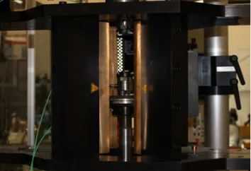
Fig. 3.Compression tests at medium strain rates.
2.2 Geometrical data acquisition
Prior to mechanical tests, geometrical measurements are performed on each sample for accurate mechanical behav-iour analysis. The apparent density () of each specimen was calculated from specimens’ weights both in air and water, on the basis of Archimedes’ principle. In order to measure precisely the geometry, two kinds of tool are used. Firstly, sample dimensions are taken with an electronic digital calliper: thickness (h), initial length (L0) and width (b). Then, the same dimensions parameters are computed from µCT data. Because of the sample size and shape, a µCT-scan device was the best application to measure correctly the section bone area (Ba). This measurement gives quantitative information regarding the porosity of sample (fig. 2).
Here, theµCT scanning was performed thanks to an 1172 SKYSKAN system, with 80 kV and 100µA setting. The voxel size was adjusted to 20.8µm.A study of shape deviation is also made on the µCT data and controls the different dimensions. The most important observation
projectile gas gun
rigid frame guides
input bar output bar
momentum trap
Strain gage 1 ( )ε,ε
Strain gage 2 (σ) .
Fig. 4.Set up for dynamic compression tests using aluminium bars.
concerns the section area on useful length that is almost constant (0.5 % variation).
2.3 Mechanical testing
As a large range of strain rates is covered to establish the evolution of cortical bone mechanical behaviour under compression loading, different experimental devices are required. For the lowest range of strain rates, a classical tensile/compression machine is used (Instron ElectroPulse Dynamic E3000) with adapted spherical seated compres-sion platens. The load cell (Dynacell) mounted on the rigid frame has a measuring range up to 3 kN. For the medium strain rates, a high speed machine (Instron VHS 65/20) is prepared to performed compression test at 0.05 s−1. For these tests, a piezo electric load cell (MR: 7 kN) is threaded at the end of a rod connected to the jack of the machine (Fig. 3). The sample is sandwiched during the test between two platens with reduced mass. The calculation of the shortening of the sample is obtained using an electro optical extensometer (Rudolph XR 200 – MR:10 mm).
A set of compression Hopkinson bars is chosen to catch the range of the higher strain rates. The configuration of the Split-Hopkinson Pressure Bars device is given in a schematic representation (Fig. 4a). The calculation of the material responses is determined on the basis of raw signals collected from full strain bridges bonded at strategic locations along input and output bars so that no superposition of the elastic incident and reflected pulses can occur during the test. Here, the set up is composed of two aluminium bars with a calibrated diameter to 25 mm and the total length of each bar is equal to 3 m (Fig. 4b).
ratio correction 0.21) using classical governing equations detailed hereafter.
2.4 Data analysis
Concerning the quasi-static tests, analyses have performed assuming that cortical structure has an elastic and isotropic behaviour. With respect to these hypotheses, strain-stress curves were obtained with different corrections using the standard normalization relations. The stress correction is made thanks to the section measurement (cortical bone area) instead of the calliper measurement.
As Kolsky technique is here used, current relative displacements and forces are calculated at first on the basis of well-known governing relations (Eqs. (1) and (2).
FIN(t)=SIN·EIN(εINC(t)+εREF(t)) (1)
FOUT(t)=SOUT·EOUT·εT RA(t) (2)
Some of them are mentioned below to access to strain-stress relations (Eqs. (3) to (6):
˙
εN(t)=
vIN(t)−vOUT(t)
lS (3)
where νINC(t) andνOUT(t) are respectively the input and
output bars’ speed andlS is the intial length of the sample.
εN(t) is the engineering strain finally obtained using a
single integration in function of time of relation (3).
vIN(t)=−CIN·(εINC(t)−εREF(t)) (4)
whereεINC(t) andεREF(t) are respectively the amplitude of
the incident and reflected pulses propagating in the input bar.CIN is the wave’s speed of the incident and reflected pulses propagating in the input bar.
vOUT(t)=−COUT·εT RA(t) (5)
where εT RA(t) is the amplitude of the transmitted pulse
and COUT is the wave speed of the transmitted pulse propagating in the output bar.
σN(t)=
SOUT·EOUT SS
·εT RA(t) (6)
whereSOUTandSS are respectively the cross section of the
output bar and the sample.EOUT is the elastic modulus of the output bar.σN(t) is the current stress calculated in the
sample.
Current displacements at intput/output bars and the shortening of the specimen are obtained with 1st order integration in function of time applied on Eq. (4) and (5), respectively. This statement is also admitted for the cal-culation of the current strain on the basis of Eq. (3). As a very fine geometrical analysis is developed usingµ CT-scanning (see Sect. 2.2), the real cross section of the sample is addressed and gives the opportunity to adjust the calculation of the stress.
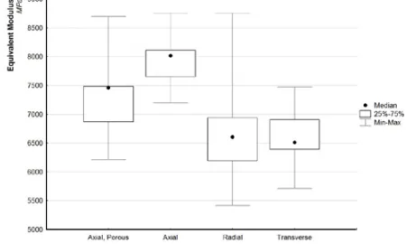
Fig. 5. Equivalent modulus for the 3 loading directions (4 categories).
3 Results
The 40 samples used in quasi-static tests are analysed to illustrate the porosity and anisotropic effects on the first bovine femur. Dynamic tests results of the second bovine femur are used to underline the velocity effects and anisotropy of cortical structure.
3.1 Quasi-static tests
Quasi-static tests are focused on the mechanical behaviour of the cortical bone regarding the loading directions and porosity effect. A large dispersion is underlined on the 40 samples. In order to relate the differences on mechanical response, the equivalent modulus is plotted in function of the 3 loading configurations (Fig. 5).
The equivalent modulus on the 40 samples is very dispersive with a maximum value at 8750 MPa and min-imum at 5500 MPa. This scattering is less important when the loading direction is considered. The box-plot repre-sentation corresponding to a 50thpercentile range is quite similar with standard deviation about 600 MPa for each loading direction classes. The equivalent modulus of the samples tested in axial configuration is higher for the sample where porosity is less than 1%. A decrease of the equivalent modulus is observed when the porosity is considered (median value at 7500 MPa against 8000 MPa without porosity). This result is in agreement with material behaviour. Concerning the radial and transverse loading directions, both median values have an equivalent modulus of 6550 MPa but dispersion is more important on radial tested samples.
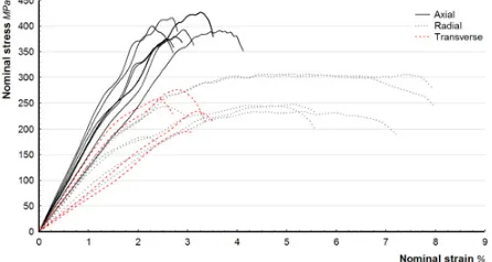
Fig. 6. Mechanical behaviour of cortical bone in compression function of the 4 loading direction configuration.
Fig. 7.SHPB results on cortical bone samples in function of the direction of the bone – Compression tests at 500 s−1.
stress at failure is very different in transverse (similar to axial loading with median value about 238 MPa) and radial direction (median value at 188 MPa). The different median values are used to plot the different mechanical behaviour of the cortical bone in function of the different loading direction in compression (Fig. 6). Here is revealed the influence of loading direction and porosity parameters on the mechanical response, particularly for the transverse direction where the strain at failure is much higher that all other cases. The influence of porosity on the mechanical response is also put into evidence for loadings in the axial direction of the bone. As the rate of porosity can be considered to correct the strain-stress curve, an increasing of the ultimate stress close to 120% is observed.
3.2 Dynamic tests
The set of 19 samples tested under compression on Split-Hopkinson bars gives the oppportunity to check if the ob-servations mentioned below are still available. For higher strain rate, cubic samples are tested in different loading configurations (Fig. 1) on the SHPB at an average strain rate closed to 500 s−1. The different strain-stress curves are plotted on the Fig. 7.
This graph presents the mechanical response in func-tion of the loading direcfunc-tions. Figure 8 gives median values for strain and stress at break coupled with associated standard deviations.
The main observation concerns the radial strain at failure (5.10%) which is more important than 2 others
Fig. 8. Mechanical behaviour of cortical bone samples in com-pression in function of 3 families.
Fig. 9.Mechanical behaviour of cortical bone in the axial direc-tion in funcdirec-tion of the strain rate (s−1).
directions (axial: 2.83% and transverse: 2.88%). This ten-dency has been already observed on the quasi-static tests. Concerning the stress at failure, the median value on the axial loading direction is about 392 MPa against 245 MPa in radial and transverse directions. On the same bovine femur, high speed machine has been used for samples loaded in the axial direction at a strain rate about 0.05 s−1. Finally 104decades are covered in terms of strain rates, so that the effect of this parameter on the material responses is clearly put into evidence whatever the direction of loading of the cubic samples. Figure 9 underlines both strain and stress sensitivity regarding the strain rate effect for the compression tests of the fresh bovine samples in the axial direction.
A difference on mechanical behaviour is observed when the strain rate is considered. The compression tests on hydraulic machine (at 0.05 s−1) and SHPB (500 s−1) are performed on the same bovine femur (fe02) and revealed an increase of equivalent modulus and stress at failure as mentioned in literature (Viano [4]). The quasi-static program comes from other bovine femur but confirms the same tendency.
4 Discussion and conclusion
anisotropy. In parallel, the authors propose a fine de-scription of the imperfections of the cross section of the samples (real shape, porosity) so as to consider geomet-rical corrections added to the material behaviour of the samples. Biological samples present a natural dispersion which coming from age, conservation, material structure (porosity) and location sample (osteon orientation . . . ). In order to reduce this dispersion, an accurate analyse of the tested samples is required and ensured in this study by theµCT scan investigation. The dimension and shape analysis is made prior to testing thanks toµCT data. The location of each sample has been considered and a special attention has been made on the porosity measurement. The Split-Hopkinson pressure bars complete the strain rate effect study. For thus investigation will be done on over vulnerable segment subjected to high speed loading. For instance head, pelvis and ribcage are candidate to tensile and compression test at the scale of coupons. For that, special design of the kolsky technique will be required to extract precisely strain-stress relation.
Acknowledgements
The present research work is also supported by the International Campus on Safety and Intermodality in Transportation (CISIT), the Nord-Pas-de-Calais Region, the Regional Delegation for Research and Technology, the Department of Higher Education and Research, and the National Centre for Scientfic Research (CNRS). The authors gratefully acknowledge the support of
these institutions. This work could not have been done without the generous gift of body donors, through the body donation program of the University of Paris. A special thought to all of them.
References
1. Lizee E., Robin S., Song E.,Proceedings of the 42nd Stapp Car Crash Conference, 115–138 (1998). 2. Iwamoto M., Kisanuki Y., Watanabe I., Furusu K.,
Miki K., Hasegawa J., Proceedings of International IRCOBI Conference, 31–42 (2002).
3. Behr M., Arnoux P.J., Serre T., Bidal S., Kang H.S., Thollon L., Cavallero C., Kayvantash K., Brunet C.,
Computer Methods in Biomechanics & Biomedical Engineering,6, 263–273 (2003).
4. Viano, D.C., Symposium on Biomechanics and Med-ical Aspects of Lower Limb Injuries, Technical Paper n˚861923 (1986)
5. Katz J.L., Journal of biomechanics, 4, 1–12 (1972)
6. Wright T.M., Hayes W.C., Medical and biological engineering,14, 671–681 (1976).
7. Crowninshield R.D., Pope M.H., Annals of Biomed-ical Engineering,2, 217–225 (1974)
8. Ferreira F., Vaz M., Simoes J.,Materials Characteri-zation,57, 71–79 (2006).