Rules for Classification and Construction
VI
Additional Rules and Guidelines
7
Guidelines for the Performance of Type Approvals
6 Test Requirements for Electrical Machinery
The following Guidelines come into force on October1st, 1999.
"General Terms and Conditions" of the respective latest edition will be applicable
(see Rules for Classification and Construction, I – Ship Technology, Part 0 – Classification and Surveys). Reproduction by printing or photostatic means is only permissible with the consent of Germanischer Lloyd.
Germanischer Lloyd AG
Head Office
Vorsetzen 35, 20459 Hamburg / Germany
Telefon +49 40 36149-0 Telefax +49 40 36149-200
[email protected] http://www.gl-group.com
Table of Contents
Section 1 General Requirements
A. Scope ... 1- 1 B. Reference to other Rules and Regulations ... 1- 1 C. Obligation to perform Type Tests ... 1- 1 D. Documentation to be submitted ... 1- 1 E. Product Requirements ... 1- 1
Section 2 Test Requirements
A. General ... 2- 1 B. Testings ... 2- 1 C. Table of Tests to be performed ... 2- 6
VI - Part 7 GL
Table of Contents Chapter 6
Section 1
General Requirements
A. Scope
The present Regulations apply to type testing of elec-trical machinery.
B. Reference to other Rules and Regulations 1. The present Regulations have been prepared on the basis of IEC publications 34 and 92-301 and/or EN 60034 (VDE 0530).
2. The following publications of Germanischer Lloyd (GL) are applicable in conjunction with the present Regulations:
– Rules for Classification and Construction, I, Part 1, Chapter 3 "Electrical Installations" – Regulations for the Performance of Type Tests,
Part 0, Procedure
– Test Requirements for Electrical / Electronic Equipment, Computers and Peripherals, Part 1.
3. Standards other than those quoted in 1. above may be acceptable, provided they are equivalent.
C. Obligation to perform Type Tests
1. Subject to the Rules for Classification and Construction of GL electrical machinery is not re-quired to be type tested. However, on application electrical machinery may be type tested.
2. If manufacturers intend to test electrical ma-chinery on their own responsibility, apart from com-pliance with other requirements type testing is condi-tional.
D. Documentation to be submitted
The documentation to be submitted corresponds to that quoted in the Regulations for the Performance of Type Tests, Part 0 - Procedure, Section 3.B:
– Description of the electrical machinery and relevant production processes (product specifi-cation)
– Relevant design documentation – Wiring schemes
– Data sheets
– Specification, data sheets and wiring schemes of any automatic voltage regulators and additional elements fitted
– Description of envisaged use
– Description of quality management system (QM Manual)
GL reserve the right of demanding additional docu-mentation to be submitted, where necessary.
E. Product Requirements
The product requirements regarding design, choice of materials, functions and operating conditions are laid down in the applicable Construction Rules and other applicable GL Regulations.
VI - Part 7
Section 2
Test Requirements
A. General
1. Choice of test specimens
Where products are mass-produced, the test specimen is to be taken from the current production. The choice is to be agreed with GL.
If the test specimens are prototypes, GL reserve the right of later on testing mass products, for the sake of comparison.
Where series are concerned, representative samples may be chosen for type testing.
2. Scope of testing
The scope of testing required for a type test will be defined by GL from case to case, depending on the product and its purpose. GL reserve the right of stipulating supplementary testings, where this is deemed necessary.
3. Testing sequence
The testing sequence is not strictly defined, but should be fixed by manufacturer and agreed with GL prior to commencement of the testings.
All tests stipulated for a particular product are to be carried out at one test specimen and/or, where mass-produced products are concerned, at the respective specimens chosen. Any deviations from this procedure require to be agreed to by GL.
4. Documentation
The tests performed are to be documented in test protocols, clearly and unmistakably. The measuring and testing instruments employed as well as the test methods applied are to be indicated.
B. Testings
1. Visual inspection and completeness test, checking of technical documentation 1.1 Procedure
The test specimen will be checked for compliance of its electrical and mechanical properties with
– the GL Construction Rules and Regulations – manufacturers' specifications
– the construction plans, computations and wiring schemes
– the standards quoted.
Visual inspection will take place prior to commencement of a type test and may have to be repeated following each test phase, such as to ascertain any visible defects at the test specimen.
1.2 Result
The test is regarded to have been passed, if the test specimen meets the requirements of the GL Construction Rules and Regulations and complies with the specification requirements and the documentation and does not show any defects.
2. Control of function of accessories and supplementary elements
2.1 Procedure
The accessories and supplementary elements (e.g. space heaters, temperature detectors, voltage and current transformers, external ventilators) will be function-tested.
2.2 Result
The test is regarded to have been passed, if construction and function meet the requirements.
3. Measurement of air gaps
3.1 Procedure
The air gaps of the machinery and, possibly, exciter machines installed are to be measured.
3.2 Result
The measurement result is regarded as being adequate, if the air gaps comply with the required values within the tolerance limits.
4. Measurement of winding resistances
4.1 Procedure
The winding resistances of the test specimen are to be measured at ambient temperature, using appropriate measuring instruments.
VI - Part 7
4.2 Result
The measurement result is regarded as being adequate, if the values measured and referred to 20°C comply with those calculated within the tolerance limits.
5. Measurement of short circuit
characteristic 5.1 Procedure
Where a.c. motors are concerned, measurements are to be conducted with the rotor being firmly braked and at constant frequency for determining the current and power consumption as a function of voltage; the starting current is to be measured. In the case of generators the current is to be measured with short-circuited stator as a function of the excitation current.
5.2 Result
The measurement result is regarded as being adequate, if the values calculated coincide to a considerable degree with those measured and if the tolerances of the values specified are not exceeded.
6. Measurement of no-load characteristic
6.1 Procedure
In the case of a.c. motors measurements are to be conducted at no load at rated frequency, such as to determine the current and power consumption as a function of voltage.
In the case of generators, with the stator terminals in open condition and at rated frequency the voltage is to be measured as a function of the excitation current.
6.2 Result
The measurement result is regarded as being adequate, if the values calculated coincide to a considerable degree with those measured and if the tolerances of the values specified are not exceeded.
7. Measurement of the load characteristic 7.1 Procedure
In the case of motors the speed is to be measured as a function of the load, and in the case of generators the voltage is to be measured as a function of the load.
7.2 Result
Unless otherwise specified, the requirements of the GL Construction Rules are to be complied with. Induction motors must not substantially deviate from their rated speed; they must not pull out. Synchronous generators must during operation at rated power and rated power factor not exceed the voltage tolerances stated in the GL Construction Rules.
During operation at rated speed from no-load speed up to the rated power and at the rated power factor the voltage must not deviate from the rated voltage by more than +/- 2.5 % (in the case of emergency generating sets +/- 3.5 %), once the transient compensation processes have been terminated.
8. Overload capability test 8.1 Procedure
Proof of overload capability of the machinery is to be furnished:
– for a.c. generators: 1.5 Irated for 2 minutes,
cos phi 0.5 inductive (lagging), with the generator voltage being kept approximately constant.
– for motors: 1.6 Mrated torque for 15 seconds
– for motors for anchor windlasses: 2 Mrated torque
for 2 minutes
Induction motors must not pull out.
8.2 Result
Unless stricter specifications exist, compliance with the requirements quoted in 8.1 is to be proved.
9. Test at decreased/increased voltage and frequency
9.1 Procedure
Proof is to be furnished of operability both at decreased and increased voltage frequency.
9.2 Result
The test is regarded to have been passed, if operability is safeguarded at the specified voltage and frequency limit values.
10. Determination of starting and breakdown torque
10.1 Procedure
For a.c. motors the starting and breakdown torque is to be determined.
10.2 Result
The torques measured are to be within the tolerance limits as per VDE / IEC.
11. Load thrown on and off, checking of AVR 11.1 Procedure
For generating sets the time behaviour of the voltage with load thrown on and off is to be oscillographed.
Chapter 6
During operation of the generator at rated speed and rated voltage the voltage must not be less than 85 % of the rated voltage nor exceed 120 %, if suddenly the load is symmetrically thrown on or off, at a current and power factor to be specified.
The generator voltage has to be constant within 1.5 sec. at Urated +/- 3 % (in the case of emergency
generators +/- 4 %). Unless any specific details on load variations are available, the requirements listed above are to be met, if the generator in no-load condition and excited to rated voltage is suddenly loaded to 60 % of its rated current and a power factor < 0.4 (lagging) and suddenly unloaded again, after the steady conditions have been achieved.
11.2 Result
Unless stricter specifications exist, compliance with the requirements quoted in 11.1 is to be proved.
12. Measurement of the rotor voltage 12.1 Procedure
For slip-ring motors the rotor voltage is to be measured.
12.2 Result
Compliance of the values calculated with those measured must be given.
13. Winding test
13.1 Procedure
Under certain conditions, e.g. where doubts exist as to the insulation strength, a winding test is to be carried out.
13.2 Result
The test specimen must be capable of resisting the increased voltage without damage during the period stipulated.
14. Overspeed test
14.1 Procedure
For proof of mechanical strength a test is to be carried out at increased speed in line with the GL Construction Rule requirements.
14.2 Result
The machinery is to be designed such as to be capable of resisting the overspeed during the period stated in the GL Construction Rules. The test is regarded as having been passed, if no permanent detrimental deformations or other deficiencies interfering with the normal operation of the machine occur.
15. Measurement of wave form
15.1 Procedure
For generators the wave form is to be recorded by oscillograph and possibly analysed.
15.2 Result
At no moment must the wave form of the interlinked no-load voltage deviate from the sinusoidal fundamental wave form by more than 5 %, related to the peak value of the first harmonic.
16. Vibration test
16.1 Procedure
The vibration behaviour of the machine is to be measured at no-load and full load and, where necessary, also as a function of speed.
16.2 Result
The vibrations generated by the machine must not exceed the limits defined for the respective use.
17. Calculation of efficiencies 17.1 Procedure
Efficiencies are to be determined for no load, part load and full load.
17.2 Result
The efficiencies calculated must not be below the values specified.
18. Heat run test
18.1 Procedure
A heat run test is to be carried out at the completely mounted machine under nominal conditions and taking into account the type of operation.
18.2 Result
The temperature rise measured must not exceed the limit values stated in the GL Construction Rules, taking into account a relevant temperature reserve (normally 10 %).
19. Determination of steady short circuit current
19.1 Procedure
For generators the steady short circuit current is to be measured under AVR control.
VI - Part 7
19.2 Result
The test is regarded as having been passed, if the generators and the excitation equipment are capable of conveying the steady short circuit for two seconds, without suffering any damage. Unless otherwise specified, the steady short circuit current must not be less than three times the rated current and/or exceed 6 times the rated current.
20. Sudden short circuit test 20.1 Procedure
For determination of the reactances and for proof of the mechanical strength of generators, a sudden short circuit test may be stipulated.
20.2 Result
The test is regarded as having been passed, if the sudden short circuit has not caused any visible damages and deformations and the function is still ensured. The reactances measured have to be within the tolerance range indicated for each practical case.
21. Testing of degree of protection 21.1 Procedure
Subject to VDE 0530 T5 / IEC 34-5 the degree of protection is to be tested.
21.2 Result
The test is regarded as having been passed, if the requirements of the referenced standards are complied with.
22. Vibration test
22.1 Procedure
The test method and test conditions are defined in the Regulations for the Performance of Type Tests, Part 1.
The test serves the purpose of furnishing proof that under the effect of induced vibrations (curve 1, excita-tion 0.7 g) the test specimen does not show any damages or temporary or permanent operational disturbances.
22.2 Result
The test is regarded as having been passed, if the specified functions have been proved and if no damages or operational disturbances have been found at the test specimen.
23. Damp heat test
23.1 Procedure
The test is to be conducted in accordance with the procedure outlined in the Regulations for the Performance of Type Tests, Part 1.
23.2 Result
The test is regarded as having been passed, if under the effect of damp heat neither any damages nor permanent or temporary operational disturbances have occurred.
24. Salt mist test
24.1 Procedure
The test is to be carried out only at machinery intended to be installed on the open deck. The procedure defined in the Regulations for the Performance of Type Tests, Part 1 is to be applied.
24.2 Result
The test is regarded as having been passed, if under the effect of salt mist the test specimen does not show any damages to components (corrosion) or any negative effects upon its operability.
25. Test for EMC
25.1 Procedure
The procedures outlined in the Regulations for the Performance of Type Tests, Part 1 are to be applied. The scope of testing will be agreed between GL and manufacturers, depending on the respective use.
25.2 Result
The test is regarded as having been passed, if neither any damages nor permanent or temporary operational disturbances have occurred.
26. High-voltage test
26.1 Procedure
Upon completion of other tests (except for 27.) the windings are to be subjected to a high-voltage test at the voltages quoted in the GL Construction Rules. Where practicable, the test is to be carried out with the machine in warm-running condition. The non-tested windings are to be grounded.
Chapter 6
26.2 Result
The high-voltage test is regarded as being passed, if each winding has resisted undamaged the test voltage as stipulated in the GL Construction Rules during the period indicated.
27. Measurement of insulation resistances 27.1 Procedure
The last test to be carried out consists in measuring the insulation resistance of each winding and of all auxil-iary and supplementary elements against earth, where practicable with the machine in warm-running con-dition. The non-tested windings and elements are to be grounded.
27.2 Result
The insulation resistance of each winding and of the supplementary elements must not fall short of the values stated in the GL Construction Rules.
Subject to Section 3.2 the scope of testing is fixed by GL in each individual case, depending on the product and scope of testing.
The following table shows normal test range.
VI - Part 7
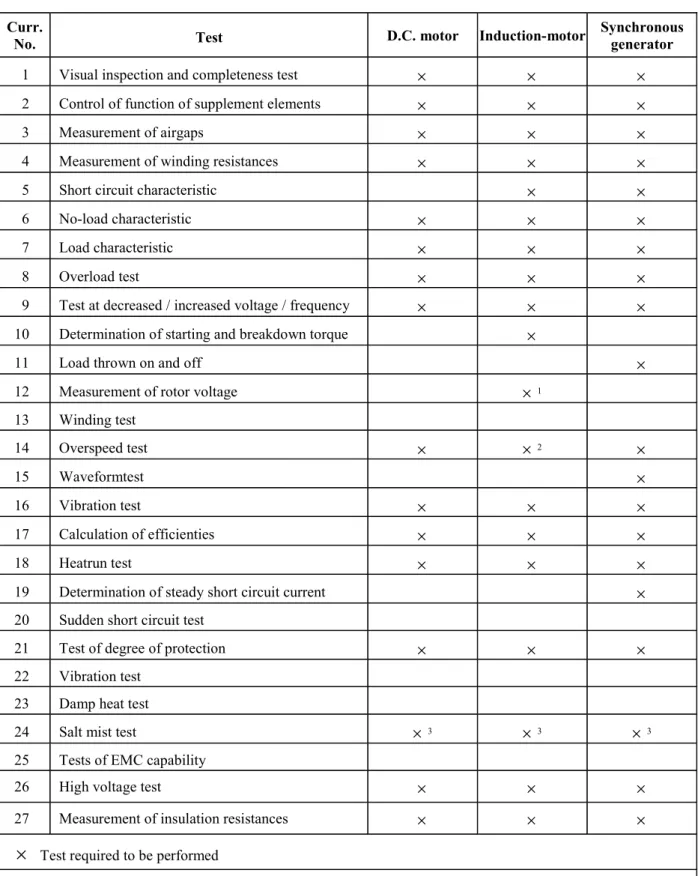
C. Table of Tests to be performed Table 2.1
Curr.
No. Test D.C. motor Induction-motor Synchronousgenerator
1 Visual inspection and completeness test
×
×
×
2 Control of function of supplement elements
×
×
×
3 Measurement of airgaps
×
×
×
4 Measurement of winding resistances
×
×
×
5 Short circuit characteristic
×
×
6 No-load characteristic
×
×
×
7 Load characteristic
×
×
×
8 Overload test
×
×
×
9 Test at decreased / increased voltage / frequency
×
×
×
10 Determination of starting and breakdown torque×
11 Load thrown on and off
×
12 Measurement of rotor voltage
×
113 Winding test 14 Overspeed test
×
×
2×
15 Waveformtest×
16 Vibration test×
×
×
17 Calculation of efficienties×
×
×
18 Heatrun test×
×
×
19 Determination of steady short circuit current
×
20 Sudden short circuit test
21 Test of degree of protection
×
×
×
22 Vibration test 23 Damp heat test
24 Salt mist test
×
3×
3×
325 Tests of EMC capability
26 High voltage test
×
×
×
27 Measurement of insulation resistances
×
×
×
×
Test required to be performed1 For slip-ring motors only
2 May be dispensed with for sqirrel-cage induction motors 3 To be performed only for machines used on the open deck
Chapter 6